Table of Contents
Advertisement
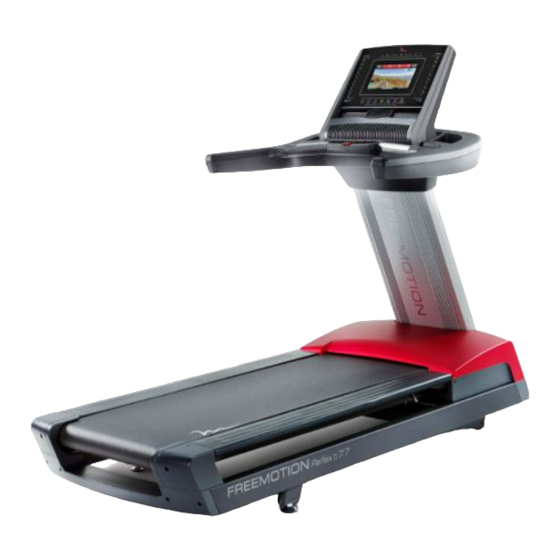
Model No. VMTL29811.0
Serial No.
Write the serial number in the space
above for reference.
Serial Number Decal
QUESTIONS?
If you have questions, or if parts
are damaged or missing,
please see HOW TO CONTACT
CUSTOMER CARE on the back
cover of this manual.
CAUTION
Read all precautions and instruc-
tions in this manual before using
this equipment. Save this manual
for future reference.
USER'S MANUAL
www.freemotionfitness.com
Advertisement
Table of Contents

Subscribe to Our Youtube Channel
Related Manuals for Freemotion VMTL29811.0


Summary of Contents for Freemotion VMTL29811.0
- Page 1 USER’S MANUAL Model No. VMTL29811.0 Serial No. Write the serial number in the space above for reference. Serial Number Decal QUESTIONS? If you have questions, or if parts are damaged or missing, please see HOW TO CONTACT CUSTOMER CARE on the back cover of this manual.
-
Page 2: Table Of Contents
LIMITED WARRANTY............. . . Back Cover FREEMOTION is a registered trademark of ICON IP, Inc. -
Page 3: Warning Decal Placement
WARNING DECAL PLACEMENT These drawings show the locations of the warning decals. If a decal is missing or illegible, call the telephone number on the front cover of this manual and request a free replacement decal. Apply the decal in the location shown. -
Page 4: Important Precautions
To reduce the risk of serious injury, read all important precautions and instructions in this manual and all warnings on your treadmill before using your treadmill. FreeMotion Fitness assumes no responsibility for personal injury or property damage sustained by or through the use of this product. - Page 5 DANGER: 20. Never leave the treadmill unattended while Always unplug the power it is running. Always remove the key, press cord immediately after use, before clean- the power switch into the off position (see ing the treadmill, and before performing the the drawing on page 6 for the location of the maintenance and adjustment procedures power switch), and unplug the power cord...
-
Page 6: Before You Begin
BEFORE YOU BEGIN Thank you for selecting the revolutionary reading this manual, please see the back cover of this FREEMOTION REFLEX T7.7 treadmill. The REFLEX manual. To help us assist you, note the product model ® T7.7 treadmill offers an impressive selection of features number and serial number before contacting us. -
Page 7: Part Identification Chart
PART IDENTIFICATION CHART Use the drawings below to identify small parts used for assembly. The number in parentheses below each draw- ing is the key number of the part, from the PART LIST near the end of this manual. The number following the key number is the quantity used for assembly. -
Page 8: Assembly
ASSEMBLY • Assembly requires two persons. • To identify small parts, see page 7. • Place all parts in a cleared area and remove the • Assembly requires the following tools: packing materials. Do not dispose of the packing the included hex key materials until you finish all assembly steps. - Page 9 2. Insert the end of the Upright Wire (111) through the looped plastic tie at the top of the Upright (81). Make sure that the Upright Wire is behind the crossbars on the Upright. Then, gently pull upward on the Upright Wire as you tighten the plastic ties around the Upright Wire.
- Page 10 4. Have a second person hold the handrail assem- bly near the Upright (81). Insert the Upright Wire Handrail Assembly (111) and the TV Cable (106) upward through the center of the handrail assembly. Slide the bracket on the handrail assembly over the crossbar on the Upright (81) and set the Bracket handrail assembly on the Upright.
- Page 11 6. Tighten two 3/8" x 3 3/4" Screws (11) with two 3/8" Flat Washers (43) into the handrail assem- bly. Start both Screws, and then tighten them. Handrail Assembly 7. Set the console assembly on a soft surface to avoid scratching the console assembly. Remove the four 3/8"...
- Page 12 9. Tighten the four 3/8" x 2 3/4" Screws (27) with two 3/8" Star Washers (2) that you removed in step 7. 10. Attach the Upright Collar (105) to the handrail assembly with two #8 x 5/8" Screws (18). Handrail Assembly 11.
-
Page 13: Operation And Adjustment
OPERATION AND ADJUSTMENT HOW TO CONNECT THE POWER CORD nominal 120-volt circuit capable of carrying 15 or more amps. To avoid overloading the circuit, do Use a Surge Suppressor not plug other electrical devices, except for low- power devices such as cell phone chargers, into Your treadmill, like other electronic equipment, can be the surge suppressor or into an outlet on the same circuit. -
Page 14: How To Upgrade The Console
United States of America (excluding Alaska, Hawaii, and Canada) and are then subject to the not available from FreeMotion Fitness, but are avail- terms provided by that country’s local authorized able at electronics stores. See the owner’s manual for the equipment you wish to connect to determine if an FreeMotion Fitness, Inc. -
Page 15: How To Use The Console
HOW TO USE THE CONSOLE FEATURES OF THE CONSOLE As you exercise, the console will display instant exer- cise feedback. You can also measure your heart rate The treadmill console offers an impressive array of using the handgrip heart rate monitor or an optional features designed to make your workouts more effec- Polar -compatible chest heart rate monitor. - Page 16 HOW TO TURN ON THE POWER HOW TO USE THE TOUCH SCREEN 1. Plug in the power cord. The console features a tablet computer with a full-color touch screen. The following information will help you See HOW TO PLUG IN THE POWER CORD on become familiar with the tablet’s advanced technology: page 13.
- Page 17 (see page 35). system of the treadmill. 4. Create an iFit Live account. To create an iFit Live account and access addi- tional workouts, videos, and several other features, please contact your FREEMOTION dealer.
- Page 18 HOW TO USE THE MANUAL MODE Note: The first time you adjust the incline, you must first calibrate the incline system (see step 4 on 1. Insert the key into the console. page 25). 5. Monitor your progress. See HOW TO TURN ON THE POWER on page 16.
- Page 19 7. Turn on the fan if desired. If desired, adjust the volume by pressing the Vol increase and decrease buttons on the console. The fan features multiple speed settings and an To pause the workout, touch one of the menu but- auto mode.
- Page 20 HOW TO USE AN ONBOARD WORKOUT If the speed or incline setting is too high or too low at any time during the workout, you can override 1. Insert the key into the console. the setting by pressing the Speed or Incline but- tons;...
- Page 21 HOW TO USE A SET-A-GOAL WORKOUT The workout will function in the same way as the manual mode (see pages 18 and 19). 1. Insert the key into the console. The workout will continue until you reach the goal See HOW TO TURN ON THE POWER on page that you set.
- Page 22 HOW TO USE AN IFIT LIVE WORKOUT Before some workouts will download, you must add them to your schedule on iFit.com. Note: To use an iFit Live workout, you must have For more information about the iFit Live work- access to a wireless network (see HOW TO USE THE outs, please see www.iFit.com.
- Page 23 HOW TO USE THE EQUIPMENT SETTINGS MODE 5. Turn on or turn off the display demo mode. The console features an equipment settings mode The console features a display demo mode, that allows you to select a language and the unit of designed to be used if the treadmill is displayed measurement, to turn on and turn off the display demo in a store.
- Page 24 8. Enable or disable the street view. HOW TO USE THE ENTERTAINMENT MODE You can disable the street view for Map workouts, The console features an entertainment mode that which will help to restrict the bandwidth used on allows you to connect the console to a remote TV. your wireless network.
- Page 25 HOW TO USE THE MAINTENANCE MODE Note: Occasionally, a firmware update may cause your console to function slightly differently. These The console features a maintenance mode that allows updates are always designed to improve your exer- you to update the console firmware, calibrate the cise experience.
- Page 26 HOW TO USE THE WIRELESS NETWORK MODE An information box will ask if you want to connect to the wireless network. Touch the Connect button The console features a wireless network mode that to connect to the network or touch the Cancel but- allows you to set up a wireless network connection.
- Page 27 HOW TO USE THE SOUND SYSTEM 3. iPod. To listen to music and the console audio on your per- Select this audio source to listen to your iPod (see sonal headphones or ear buds, plug the audio wire on HOW TO USE THE SOUND SYSTEM at the left). your headphones into the audio jack in the center of the lower section of the console.
-
Page 28: How To Move The Treadmill
HOW TO MOVE THE TREADMILL Due to the size and weight of the treadmill, moving 2. After the treadmill is placed in the location where it requires two or three persons. it will be used, make sure that the leveling feet rest firmly on the floor. -
Page 29: Preventive Maintenance
PREVENTIVE MAINTENANCE Regular maintenance is necessary for optimal per- 2. Using a hand-held vacuum, clean the area under the Motor Hood (not shown). Be careful to avoid formance and long life of the treadmill. Please read and follow all instructions below. If the treadmill is touching any components. - Page 30 REPLACING THE WALKING PLATFORM AND THE 3. Remove the indicated #8 x 1/2" Machine Screws WALKING BELT (21) from each side of the treadmill (only one side is shown). Inspect the walking platform periodically for wear. If there is any wood showing through the phenolic coat- ing, or if the surface is damaged, the walking platform should be replaced.
- Page 31 5. Remove the Footrails (114, 122). Remove the two 1/4" x 3/4" Bolts (9), the two 5/16" x 1 1/2" Bolts (8), and the two 5/16" Locknuts (38). Remove the two 5/16" x 2 1/2" Screws (7), the two 5/16" Lock 89, 85 Washers (not shown), and the two 5/16"...
- Page 32 7. The tension of the Walking Belt (46) now needs to be adjusted. Center the Walking Belt if necessary (see page 35). Then, plug in the power cord, step onto the foot rails, insert the key into the console, and press the Start/Stop button.
-
Page 33: Six-Month Preventive Maintenance Record
SIX-MONTH PREVENTIVE MAINTENANCE RECORD Photocopy this form and use it to record the preventive maintenance performed on the treadmill. Each copy of the form can be used for six months (26 weeks). When maintenance is performed, write the date in the appropriate spaces. -
Page 34: Troubleshooting
TROUBLESHOOTING Most treadmill problems can be solved by following SYMPTOM: The incline of the treadmill does not the simple steps below. Find the symptom that change correctly applies, and follow the steps listed. If further assis- tance is needed, see the front cover of this manual. a. - Page 35 SYMPTOM: The walking belt is off-center or slips SYMPTOM: The iFit Live mode does not function when walked on correctly a. If the walking belt is off-center, first remove the a. If the iFit Live mode is not functioning correctly, key and UNPLUG THE POWER CORD.
-
Page 36: Exercise Guidelines
EXERCISE GUIDELINES Burning Fat—To burn fat effectively, you must exer- WARNING: cise at a low intensity level for a sustained period of Before beginning this time. During the first few minutes of exercise, your or any exercise program, consult your physi- body uses carbohydrate calories for energy. - Page 37 SUGGESTED STRETCHES The correct form for several basic stretches is shown at the right. Move slowly as you stretch —never bounce. 1. Toe Touch Stretch Stand with your knees bent slightly and slowly bend forward from your hips. Allow your back and shoulders to relax as you reach down toward your toes as far as possible.
-
Page 38: Part List
PART LIST Model No. VMTL29811.0 R0312A Key No. Qty. Description Key No. Qty. Description 3/8" x 3 1/4" Screw Reed Switch 3/8" Star Washer Controller #8 x 5/8" Machine Screw Frame #8 x 1/2" Ground Screw Drive Motor 3/8" x 1 1/2" Bolt Motor Bushing 3/8"... - Page 39 Key No. Qty. Description Key No. Qty. Description Console Assembly Wheel Axle Rear Resistor Bracket Caution Decal Resistor Voltage Warning Decal Front Resistor Bracket English Warning Decal Upright Collar Right Footrail TV Cable Motor Bracket Key/Clip 5/16" x 3/8" Washer Head Bolt Wheel Bushing Platform Bracket Bushing Flat Wheel Bushing...
-
Page 40: Exploded Drawing
EXPLODED DRAWING A Model No. VMTL29811.0 R0312A... - Page 41 EXPLODED DRAWING B Model No. VMTL29811.0 R0312A...
- Page 42 EXPLODED DRAWING C Model No. VMTL29811.0 R0312A...
- Page 43 EXPLODED DRAWING D Model No. VMTL29811.0 R0312A...
-
Page 44: How To Contact Customer Care
1500 South 1000 West Logan, UT 84321-9813 United States LIMITED WARRANTY FreeMotion Fitness warrants this product to be free from 7. Damage caused by improper wiring or insufficient electrical defects in workmanship and material under normal use and current. service conditions. The warranty period commences on the invoice date of purchase.
Need help?
Do you have a question about the VMTL29811.0 and is the answer not in the manual?
Questions and answers