Table of Contents
Advertisement
www.iconfitness.com
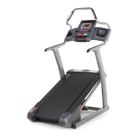
Model No. SFTL19609.0
Serial No.
Write the serial number in the space
above for reference.
Serial Number
QUESTIONS?
If you have questions, or if parts are
damaged or missing, DO NOT
CONTACT THE STORE; please
contact Customer Care.
IMPORTANT: Please register this
product (see the limited warranty
on the back cover of this manual)
before contacting Customer Care.
1-800-999-3756
CALL TOLL-FREE:
Mon.–Fri. 6 a.m.–6 p.m. MT
Sat. 8 a.m.–4 p.m. MT
ON THE WEB:
www.iconservice.com
CAUTION
Read all precautions and instruc-
tions in this manual before using
this equipment. Save this manual
for future reference.
Decal
USER'S MANUAL
Advertisement
Table of Contents

Subscribe to Our Youtube Channel
Related Manuals for Freemotion TT 50


Summary of Contents for Freemotion TT 50
- Page 1 www.iconfitness.com USER'S MANUAL Model No. SFTL19609.0 Serial No. Write the serial number in the space above for reference. Serial Number Decal QUESTIONS? If you have questions, or if parts are damaged or missing, DO NOT CONTACT THE STORE; please contact Customer Care. IMPORTANT: Please register this product (see the limited warranty on the back cover of this manual)
-
Page 2: Table Of Contents
Apply the decal in the location shown. Note: The decals may not be shown at actual size. FREEMOTION is a registered trademark of ICON IP, Inc. -
Page 3: Important Precautions
12. To purchase a surge suppressor, see it and 2 ft. (0.6 m) on each side. Do not place your local FREEMOTION dealer or call the the incline trainer on any surface that blocks telephone number on the front cover of this air openings. - Page 4 18. The incline trainer is capable of high speeds. 23. Inspect and properly tighten all parts of the Adjust the speed in small increments to incline trainer regularly. avoid sudden jumps in speed. 24. Never insert or drop any object into any 19.
-
Page 5: Before You Begin
Thank you for selecting the revolutionary reading this manual, please see the front cover of this FREEMOTION TT 50 TERRAIN TRAINER. The TT manual. To help us assist you, note the product model ® 50 TERRAIN TRAINER offers a selection of features number and serial number before contacting us. -
Page 6: Assembly
ASSEMBLY To hire an authorized service technician to assemble the incline trainer, call 1-800-445-2480. Assembly requires two persons. Set the incline trainer in a cleared area and remove all packing materials. Do not dispose of the packing materials until assembly is completed. Note: The underside of the incline trainer walking belt is coated with high-performance lubricant. - Page 7 1. Make sure that the power cord is unplugged. With the help of a second person, tip the incline trainer onto its left side. Have the second per- son hold the incline trainer to prevent it from tipping. Attach four Base Feet (10) and two Base Foot Spacers (11) to the Base (80) with four #8 x 1"...
- Page 8 3. With the help of a second person, carefully tip the incline trainer down so that the Base (80) is flat on the floor. Attach a Wheel (12) to each side of the Base (80) with a 3/8" x 2 1/2" Bolt (6) and a 3/8" Nut (7) (only one side is shown).
- Page 9 6. Hold the Pulse Handrail (86) near the Handrail Assembly (88). Insert the Left and Right Pulse Wires (90, 91) into the top of the Handrail Assembly and out of the holes in the sides. Slide the Pulse Handrail (86) into the Handrail Assembly (88).
- Page 10 8. Have a second person hold the Console (85) near the Console Cover (87). Insert the wires from the Console through the indicated hole. Connect the Upright Wire (78), the Left and Right Pulse Wires (90, 91), and the Ground Wire (97) to the wires extending from the Console (85).
- Page 11 10. Attach the Console Back (89) to the Console Cover (87) with eight #8 x 3/4" Screws (1). Start all eight Screws before tightening any of them. Do not overtighten the Screws. Make sure no wires are pinched. 11. Press the Left and Right Accessory Trays (99, 100) into the Console Cover (87).
-
Page 12: Operation And Adjustment
Grounded Outlet Box drawing 1 at the right). To purchase a surge sup- Adapter pressor, see your local FREEMOTION dealer or call Surge Suppressor the telephone number on the front cover of this manual and order part number 146148, or see your local electronics store. - Page 13 CONSOLE DIAGRAM Audio Jack FEATURES OF THE CONSOLE You can also listen to your favorite workout music or audio books with the consoleʼs premium stereo sound The incline trainer console offers an impressive array system while you get in shape. of features designed to make your workouts more ef- To turn on the power, see page 14.
- Page 14 HOW TO TURN ON THE POWER HOW TO USE THE MANUAL MODE IMPORTANT: If the incline trainer has been ex- 1. Insert the key into the console. posed to cold temperatures, allow it to warm to room temperature before turning on the power. If See HOW TO TURN ON THE POWER at the left.
- Page 15 4. Change the incline of the incline trainer as To reset the console, press the iFit Menu button in desired. the upper right corner of the screen. To pause the workout, press the Pause button. To continue the To change the incline of the incline trainer, press workout, press the Resume button or the Start but- the Elevation increase and decrease buttons or ton.
- Page 16 HOW TO USE A CALORIE BURN WORKOUT OR During the workout, the profile will show your AN ALL-TERRAIN TRAILS WORKOUT progress. Press the Display increase and decrease buttons repeatedly to view the profile. The red line 1. Insert the key into the console. will indicate the current segment of the workout.
- Page 17 5. Monitor your progress with the display. 4. Start the workout. See step 5 on page 15. The display can also show Press the Start Workout button to start the work- a profile of the incline settings of the workout. out.
- Page 18 HOW TO USE THE IFIT LIVE MODE couraged to try to correct the interference by one of the following measures: The iFit Live mode allows your incline trainer to com- municate with your wireless network and unlocks excit- • Reorient or relocate the receiving antenna. ing new features.
- Page 19 HOW TO USE THE SETTINGS MODE must press the Use Encryption button and fill in the entry boxes. If desired, you may also set a static IP The console features a settings mode that allows you address and/or a static domain name server to connect your incline trainer to your own wireless (DNS).
- Page 20 5. Log in to your iFit Live account. 1. Select the settings mode. Enter your user name and password using the key- Insert the key into the console (see step 1 on page board on the screen. To use numbers or other 14).
-
Page 21: How To Move The Incline Trainer
HOW TO MOVE THE INCLINE TRAINER Before moving the incline trainer, insert the key into the console, raise the incline to the maximum incline level, remove the key, and unplug the power cord. Console Due to the size and weight of the incline trainer, moving it requires two or three persons. -
Page 22: Troubleshooting
TROUBLESHOOTING Most incline trainer problems can be solved by following the steps below. Find the symptom that applies, and follow the steps listed. If further assistance is needed, please see the front cover of this manual. PROBLEM: The power does not turn on SOLUTION: a. - Page 23 Locate the Reed Switch (55) and the Magnet (41) on the left side of the Pulley (42). Turn the Pulley until the View Magnet is aligned with the Reed Switch. Make sure that the gap between the Magnet and the Reed 1/8 in.
- Page 24 PROBLEM: The walking belt is off-center or slips when walked on SOLUTION: a. If the walking belt is off-center, remove the key and UNPLUG THE POWER CORD. If the walking belt has shifted to the left, use the hex key to turn the left idler roller bolt clockwise 1/2 of a turn;...
-
Page 25: Exercise Guidelines
EXERCISE GUIDELINES WARNING: Burning Fat—To burn fat effectively, you must exer- cise at a low intensity level for a sustained period of Before beginning any time. During the first few minutes of exercise, your exercise program, consult your physician. body uses carbohydrate calories for energy. Only after This is especially important for persons over the first few minutes of exercise does your body begin age 35 or persons with pre-existing health... -
Page 26: Part List
PART LIST—Model No. SFTL19609.0 R1209B To locate the parts listed below, see the EXPLODED DRAWING near the end of this manual. Key No. Qty. Description Key No. Qty. Description #8 x 3/4" Screw Grommet #8 x 1" Tek Screw Belly Pan Cover 1/4"... - Page 27 Key No. Qty. Description Key No. Qty. Description Incline Sensor Wire – 4" White Wire, M/F Pulse Handle Back – 6" Blue Wire, M/F Filter – 10" Brown Wire, 2F PC Power Supply – Userʼs Manual Key/Clip Note: Specifications are subject to change without notice. For information about ordering replacement parts, see the back cover of this manual.
-
Page 28: Exploded Drawing
EXPLODED DRAWING A—Model No. SFTL19609.0 R1209B... - Page 29 EXPLODED DRAWING B—Model No. SFTL19609.0 R1209B...
- Page 30 EXPLODED DRAWING C—Model No. SFTL19609.0 R1209B...
- Page 31 EXPLODED DRAWING D—Model No. SFTL19609.0 R1209B...
-
Page 32: Ordering Replacement Parts
ORDERING REPLACEMENT PARTS To order replacement parts, please see the front cover of this manual. To help us assist you, be prepared to provide the following information when contacting us: • the model number and serial number of the product (see the front cover of this manual) •...
Need help?
Do you have a question about the TT 50 and is the answer not in the manual?
Questions and answers