Table of Contents
Advertisement
T U B E
D R I V E N
P R O G R A M M A B L E
2 4 - B I T
D S P
G U I T A R
P R E A M P
U
'
M
SER
S
ANUAL
May be covered by one or more of the following: U.S. Patents #4538297, 4647876, 4696044, 4745309, 4881047, 4893099, 5124657, 5263091, 5268527, 5319713, 5333201,
5402498, 5493617 and 5638452. Other patents pending. Foreign patents pending.
Advertisement
Table of Contents

Related Manuals for Rocktron VooDu Valve Online


Summary of Contents for Rocktron VooDu Valve Online
- Page 1 T U B E D R I V E N P R O G R A M M A B L E 2 4 - B I T D S P G U I T A R P R E A M P ANUAL May be covered by one or more of the following: U.S.
- Page 2 Your VooDu Valve Online has been tested and complies with the following Standards and Directives as set forth by the European Union: Council Directive(s): 89/336/EEC Electromagnetic Compatibility Standard(s): EN55022, EN50082-1 This means that this product has been designed to meet stringent guidelines on how much RF energy it can emit, and that it should be immune from other sources of interference when properly used.
-
Page 3: Table Of Contents
1. Introduction ....................1 2. Quick Setup ....................3 3. Front Panel ....................4 4. Rear Panel ....................6 5. Connections ....................8 6. Operating Format..................11 7. Voodu Valve™ Configurations ..............33 8. Operating the Voodu Valve™ ..............69 Restoring a single factory preset: .................. - Page 4 The Voodu Valve Online features presets created and uploaded by Rocktron users from all over the world to Rocktron's World Wide Web site. These presets can be easily updated from the "Patch Bay" at Rocktron's web page. In addition, you can also upload your own custom presets to share with other online users.
- Page 5 OPERATING PRECAUTIONS NOTE: IT IS VERY IMPORTANT THAT YOU READ THIS SECTION TO PROVIDE YEARS OF TROUBLE FREE USE. THIS UNIT REQUIRES CAREFUL HANDLING. All warnings on this equipment and in the operating instructions should be adhered to and all operating instructions should be followed. Do not use this equipment near water.
- Page 6 SELECTING A PRESET STORING CHANGED PARAMETERS STEP 1 Turn the PRESET control to the desired preset. STEP 7 Press the STORE button to start the storing procedure. STEP 2 Press the RECALL button to call up the selected preset. STEP 8 If you wish to save the altered preset in the current preset location, press the STORE button a second time.
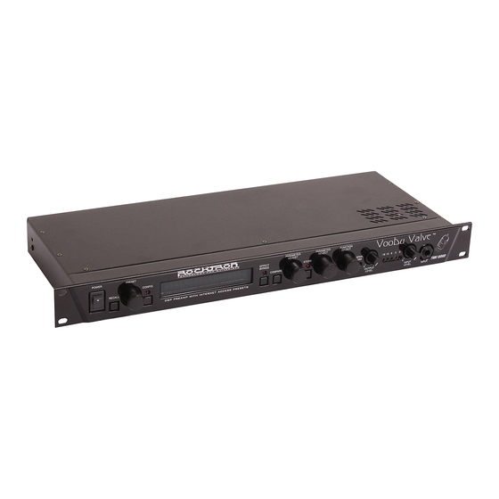
- Page 7 POWER switch RECALL button This button is used to recall the displayed preset. PRESET control This control scrolls through the successive presets. CONFIG button/led The status of this button determines whether the Voodu Valve™ will display either the preset number and title or the configuration of the currently displayed preset.
- Page 8 PARAMETER ADJUST control This control is used to adjust a displayed parameter value. When the parameter is changed from its original value, the LED above the STORE button will light until either the new value is stored, a new preset is selected or the parameter is returned to its original value.
- Page 9 For more information on this feature, refer to the "Tap Delay" section in Chapter 8. REMOTE jack This 7-pin DIN connector is provided for the connection of a Rocktron All ™ Access MIDI footswitch, which can be configured to act as a dedicated remote footswitch for the Voodu Valve.
- Page 10 "PHANTOM POWER" jack on the Voodu Valve. This will power the Rocktron MIDI foot controller through pins 6 and 7 of the MIDI cable connecting the two units. A 7-pin MIDI cable must be used and is available from your Rocktron dealer.
- Page 11 ™ Using the Voodu Valve with a stereo power amp and guitar cabinets...
- Page 12 ™ Using the Voodu Valve direct into a mixing console...
-
Page 13: Front Panel
The Voodu Valve provides 254 stored sounds called presets . Any of the 254 presets can be called up at any time via the front panel PRESET control (used to select a preset) and RECALL button (used to call up the selected preset), or by a remote MIDI footswitch. The root of each preset’s sound is its configuration . - Page 14 Voodu Valve Functions and Parameter Descriptions Each Voodu Valve preset is divided up into individual blocks called functions (such as "Mixer", "Reverb", etc.). Within each function of each configuration is a set of controls which allow you to manipulate various aspects of that function. These controls are called parameters .
- Page 15 The MUTE parameter allows you to mute the output of the Voodu Valve. This feature is especially useful when changing guitars during a live set. If a Rocktron All Access™ is used in remote mode with the Voodu Valve, a single All Access button can be configured as a momentary switch which will mute the output when it is held down.
- Page 16 The next function displayed after turning the FUNCTION SELECT control is the Mixer function. The Mixer function parameters are included in all presets—regardless of which configuration is currently recalled—although the parameter values stored in this function are only for the currently recalled preset. This digital mixer allows you to control most signal levels pertaining to each preset’s configuration and stores these levels for each preset.
- Page 17 The HIGH GAIN function is only accessible in configurations which display "H-GAIN" in the configuration title. The preamp stage in these configurations is set up to provide high gain levels for maximum sustain and distortion. The PARAMETER SELECT control will allow you to access these High Gain parameters: TUBE GAIN The TUBE GAIN parameter sets the amount of drive at the input of the tube stage.
- Page 18 The LOW GAIN function is only accessible in configurations which display "L-GAIN" in the configuration title. The preamp stage in these configurations provides four distortion types, and can also be used for clean tones. The PARAMETER SELECT control will allow you to access these Low Gain parameters: TUBE GAIN The TUBE GAIN parameter sets the amount of drive at the input of the tube stage.
- Page 19 The HUSH ® function is accessible in all presets—regardless of the configuration currently recalled. HUSH is Hush Systems’ patented single-ended noise reduction system. The HUSH system contained in the Voodu Valve, though modeled after the latest analog HUSH design, is a fully digital implementation achieved through Digital Signal Processing (DSP).
- Page 20 The PRE EQ (EXPERT) function is available in all presets—regardless of which configuration is currently recalled. This function allows you to shape the tone prior to the distortion stage. Considerable tone variations can be achieved by modifying these pre-distort EQ parameters. The PARAMETER SELECTcontrol will allow you to access these PRE EQ parameters: LF LEVEL The pre-LF (low frequency) LEVEL parameter allows you to cut or...
- Page 21 The POST EQ (EXPERT) function is available in all presets—regardless of which configuration is currently recalled. This function allows you shape the tone after it has passed through the distortion stage. These post-distortion EQ parameters have a more dramatic effect on the overall tone than the pre-distortion parameters.
- Page 22 The COMPRESSOR function is available only in configurations which display "L- GAIN" in the configuration title. This function allows you to compress the signal prior to the distortion stage. Com- pression is often used to maintain an even level when using clean tones, and also to increase sustain when using distorted tones.
- Page 23 The SPEAKER SIMULATOR function is included in all presets and provides a realistic approximation of a miked speaker cabinet for applications involving connecting the Voodu Valve directly to a mixing board, recording system or other full range system. When a preset is recalled which has the Speaker Simulator on for either the left channel or both channels, the front panel SPKR SIM LED will light.
- Page 24 To use an expression pedal as a wah-wah pedal, connect it to a MIDI controller (such as a Rocktron MIDI Mate™) and set the controller’s MIDI channel to correspond with the Voodu Valve’s receiving MIDI channel. Then set the pedal’s control number on the MIDI Mate™...
- Page 25 The PHASER function is available only in configurations displaying "PHAS" in the configuration title. Phase shifting involves splitting the input signal into two signals, then shifting the phase of different frequencies of one signal and mixing it back with the original signal. The PARAMETER SELECT control will allow you to access these PHASER parameters: PHASER I/O The PHASER I/O parameter determines whether the Phaser is active for...
- Page 26 The FLANGER function is available only in configurations displaying "FLAN" in the configuration title. Flanging involves splitting the input signal into at least two individual delayed signals (Voice 1 and Voice 2) , then modulating these delayed signals so that, when summed back with the direct signal, phase cancellations will occur at some frequencies while peaks in the response will occur at others.
- Page 27 The TREMOLO function is available only in configurations displaying “TREM” in the configuration title. The Tremolo effect continuously varies the volume of the signal. The PARAMETER SELECT control will allow you to access these TREMOLO parameters: TREMOLO The TREMOLO I/O parameter determines whether the Tremolo is active or bypassed for the current preset.
- Page 28 The PITCH function is available only in configurations displaying “PSHF” in the configuration title. Pitch Shifting is used to change the pitch of the input signal to produce a harmony note based on the input signal. The harmony voice may be of any fixed interval—up to one octave above the input signal to two octaves below—and is selected in 20-cent increments.
- Page 29 20 cents).This allows for smooth pitch change when an expression controller (such as a volume ™ ™ pedal used with a Rocktron All Access or MIDI Mate foot controller) is assigned to the PITCH parameter to change the pitch by remote means.
- Page 30 The CHORUS function is available only in configurations displaying “CRS” in the configuration title. The Chorus effect in the Voodu Valvedddd is produced by using two delayed signals (Voice 1 and Voice 2), detuning these delayed signals (slightly changing their pitch), then modulating the detune effect so that the amount of pitch detune is constantly varying.
- Page 31 PAN 2 The PAN 2 parameter allows you to pan Voice 2 to the left or right channel. DEPTH 2 The DEPTH 2 parameter adjusts the amount of modulation of the Voice 2 signal. A lower depth setting will produce a more subtle detune effect, while a higher setting will produce a more extreme detuning of Voice 2.
- Page 32 The DELAY function is available in all presets. Delay is a reproduction of the input signal, occurring at a prescribed time (usually expressed in milliseconds) following the input signal. The Voodu Valve™ provides two discrete delays (Delay 1 and Delay 2), each of which has its own parameters to deter- mine its particular characteristics.
- Page 33 SOURCE 2 The SOURCE 2 parameter is used to select whether the Source 2 input will be the VOICE 2 output from the previous effect in the signal chain or the direct signal (DIR). DLY HF DAMP The DELAY HIGH FREQUENCY DAMPING parameter controls the amount of high frequency content in the delayed and regenerated signals.
- Page 34 The REVERB function is available in all presets. Reverb is a multitude of echos spaced so close together that, to the human ear, seem as a single continuous sound. These echos gradually decrease in intensity until they are ultimately absorbed by the boundaries and obstacles within a room. As the sound waves from the sound source strike the boundaries of a room, a portion of the energy is reflected away from the obstacle while another portion is absorbed into it—thereby causing both the continuance of sound as well as the decaying or “dying out”...
- Page 36 FUNCTION PARAMETER LIST RANGE (via FUNCTION SELECT control) (via PARAMETER SELECT control) (via PARAMETER ADJUST control) GLOBAL OUTPUT (Output Level) Stereo, Mono SPKR SIM (Speaker Simulator Lock) Unlock, Lock Off, Lock L, Lock B HUSH OFFSET -10 dB to +30 dB MUTE Off, On MIXER...
- Page 37 (cont'd) FUNCTION PARAMETER LIST RANGE (via FUNCTION SELECT control) (via PARAMETER SELECT control) (via PARAMETER ADJUST control) SPEAKER SIM SPKR SIM (Speaker Simulator Status) Off, Left, Both SPKR TYPE (Speaker Type) 15, 12, 10, 8, Full MIC POSITION (Microphone Position) -15dB to +15dB REACTANCE (Reactance Level) -15dB to +15dB...
- Page 39 FUNCTION PARAMETER LIST RANGE (via FUNCTION SELECT control) (via PARAMETER SELECT control) (via PARAMETER ADJUST control) GLOBAL OUTPUT (Output Level) Stereo, Mono SPKR SIM (Speaker Simulator Lock) Unlock, Lock Off, Lock L, Lock B HUSH OFFSET -10dB to +30dB MUTE Off, On MIXER VOLUME (V olume Level)
- Page 40 (cont'd) FUNCTION PARAMETER LIST RANGE (via FUNCTION SELECT control) (via PARAMETER SELECT control) (via PARAMETER ADJUST control) SPEAKER SIM SPKR SIM (Speaker Simulator Status) Off, Left, Both SPKR TYPE (Speaker Type) 15, 12, 10, 8, Full MIC POSITION (Microphone Position) -15dB to +15dB REACTANCE (Reactance Level) -15dB to +15dB...
- Page 42 FUNCTION PARAMETER LIST RANGE (via FUNCTION SELECT control) (via PARAMETER SELECT control) (via PARAMETER ADJUST control) GLOBAL OUTPUT (Output Level) Stereo, Mono SPKR SIM (Speaker Simulator Lock) Unlock, Lock Off, Lock L, Lock B HUSH OFFSET -10dB to +30dB MUTE Off, On MIXER VOLUME (V olume Level)
- Page 43 (cont'd) FUNCTION PARAMETER LIST RANGE (via FUNCTION SELECT control) (via PARAMETER SELECT control) (via PARAMETER ADJUST control) SPEAKER SIM SPKR SIM (Speaker Simulator Status) Off, Left, Both SPKR TYPE (Speaker Type) 15, 12, 10, 8, Full MIC POSITION (Microphone Position) -15dB to +15dB REACTANCE (Reactance Level) -15 B to +15dB...
- Page 45 FUNCTION PARAMETER LIST RANGE (via FUNCTION SELECT control) (via PARAMETER SELECT control) (via PARAMETER ADJUST control) GLOBAL OUTPUT (Output Level) Stereo, Mono SPKR SIM (Speaker Simulator Lock) Unlock, Lock Off, Lock L, Lock B HUSH OFFSET -10dB to +30dB MUTE Off, On MIXER VOLUME (V olume Level)
- Page 46 (cont'd) FUNCTION PARAMETER LIST RANGE (via FUNCTION SELECT control) (via PARAMETER SELECT control) (via PARAMETER ADJUST control) SPEAKER SIM SPKR SIM (Speaker Simulator Status) Off, Left, Both SPKR TYPE (Speaker Type) 15, 12, 10, 8, Full MIC POSITION (Microphone Position) -15dB to +15dB REACTANCE (Reactance Level) -15dB to +15dB...
- Page 48 FUNCTION PARAMETER LIST RANGE (via FUNCTION SELECT control) (via PARAMETER SELECT control) (via PARAMETER ADJUST control) GLOBAL OUTPUT (Output Level) Stereo, Mono SPKR SIM (Speaker Simulator Lock) Unlock, Lock Off, Lock L, Lock B HUSH OFFSET -10dB to +30dB MUTE Off, On MIXER VOLUME (V olume Level)
- Page 49 (cont'd) FUNCTION PARAMETER LIST RANGE (via FUNCTION SELECT control) (via PARAMETER SELECT control) (via PARAMETER ADJUST control) SPEAKER SIM SPKR SIM (Speaker Simulator Status) Off, Left, Both SPKR TYPE (Speaker Type) 15, 12, 10, 8, Full MIC POSITION (Microphone Position) -15dB to +15dB REACTANCE (Reactance Level) -15dB to +15dB...
- Page 51 FUNCTION PARAMETER LIST RANGE (via FUNCTION SELECT control) (via PARAMETER SELECT control) (via PARAMETER ADJUST control) GLOBAL OUTPUT (Output Level) Stereo, Mono SPKR SIM (Speaker Simulator Lock) Unlock, Lock Off, Lock L, Lock B HUSH OFFSET -10dB to +30dB MUTE Off, On MIXER VOLUME (V olume Level)
- Page 52 (cont'd) FUNCTION PARAMETER LIST RANGE (via FUNCTION SELECT control) (via PARAMETER SELECT control) (via PARAMETER ADJUST control) SPEAKER SIM SPKR SIM (Speaker Simulator Status) Off, Left, Both SPKR TYPE (Speaker Type) 15, 12, 10, 8, Full MIC POSITION (Microphone Position) -15dB to +15dB REACTANCE (Reactance Level) -15dB to +15dB...
- Page 54 FUNCTION PARAMETER LIST RANGE (via FUNCTION SELECT control) (via PARAMETER SELECT control) (via PARAMETER ADJUST control) GLOBAL OUTPUT (Output Level) Stereo, Mono SPKR SIM (Speaker Simulator Lock) Unlock, Lock Off, Lock L, Lock B HUSH OFFSET -10dB to +30dB MUTE Off, On MIXER VOLUME (V olume Level)
- Page 55 (cont'd) FUNCTION PARAMETER LIST RANGE (via FUNCTION SELECT control) (via PARAMETER SELECT control) (via PARAMETER ADJUST control) SPEAKER SIM SPKR SIM (Speaker Simulator Status) Off, Left, Both SPKR TYPE (Speaker Type) 15, 12, 10, 8, Full MIC POSITION (Microphone Position) -15dB to +15dB REACTANCE (Reactance Level) -15dB to +15dB...
- Page 57 FUNCTION PARAMETER LIST RANGE (via FUNCTION SELECT control) (via PARAMETER SELECT control) (via PARAMETER ADJUST control) GLOBAL OUTPUT (Output Level) Stereo, Mono SPKR SIM (Speaker Simulator Lock) Unlock, Lock Off, Lock L, Lock B HUSH OFFSET -10dB to +30dB MUTE Off, On MIXER VOLUME (V olume Level)
- Page 58 (cont'd) FUNCTION PARAMETER LIST RANGE (via FUNCTION SELECT control) (via PARAMETER SELECT control) (via PARAMETER ADJUST control) SPEAKER SIM SPKR SIM (Speaker Simulator Status) Off, Left, Both SPKR TYPE (Speaker Type) 15, 12, 10, 8, Full MIC POSITION (Microphone Position) -15dB to +15dB REACTANCE (Reactance Level) -15dB to +15dB...
- Page 60 FUNCTION PARAMETER LIST RANGE (via FUNCTION SELECT control) (via PARAMETER SELECT control) (via PARAMETER ADJUST control) GLOBAL OUTPUT (Output Level) Stereo, Mono SPKR SIM (Speaker Simulator Lock) Unlock, Lock Off, Lock L, Lock B HUSH OFFSET -10dB to +30dB MUTE Off, On MIXER VOLUME (V olume Level)
- Page 61 (cont'd) FUNCTION PARAMETER LIST RANGE (via FUNCTION SELECT control) (via PARAMETER SELECT control) (via PARAMETER ADJUST control) SPEAKER SIM SPKR SIM (Speaker Simulator Status) Off, Left, Both SPKR TYPE (Speaker Type) 15, 12, 10, 8, Full MIC POSITION (Microphone Position) -15dB to +15dB REACTANCE (Reactance Level) -15dB to +15dB...
- Page 63 FUNCTION PARAMETER LIST RANGE (via FUNCTION SELECT control) (via PARAMETER SELECT control) (via PARAMETER ADJUST control) GLOBAL OUTPUT (Output Level) Stereo, Mono SPKR SIM (Speaker Simulator Lock) Unlock, Lock Off, Lock L, Lock B HUSH OFFSET -10dB to +30dB MUTE Off, On MIXER VOLUME (V olume Level)
- Page 64 (cont'd) FUNCTION PARAMETER LIST RANGE (via FUNCTION SELECT control) (via PARAMETER SELECT control) (via PARAMETER ADJUST control) SPEAKER SIM SPKR SIM (Speaker Simulator Status) Off, Left, Both SPKR TYPE (Speaker Type) 15, 12, 10, 8, Full MIC POSITION (Microphone Position) -15dB to +15dB REACTANCE (Reactance Level) -15dB to +15dB...
- Page 66 FUNCTION PARAMETER LIST RANGE (via FUNCTION SELECT control) (via PARAMETER SELECT control) (via PARAMETER ADJUST control) GLOBAL OUTPUT (Output Level) Stereo, Mono SPKR SIM (Speaker Simulator Lock) Unlock, Lock Off, Lock L, Lock B HUSH OFFSET -10dB to +30dB MUTE Off, On MIXER VOLUME (V olume Level)
- Page 67 (cont'd) FUNCTION PARAMETER LIST RANGE (via FUNCTION SELECT control) (via PARAMETER SELECT control) (via PARAMETER ADJUST control) SPEAKER SIM SPKR SIM (Speaker Simulator Status) Off, Left, Both SPKR TYPE (Speaker Type) 15, 12, 10, 8, Full MIC POSITION (Microphone Position) -15dB to +15dB REACTANCE (Reactance Level) -15dB to +15dB...
- Page 69 FUNCTION PARAMETER LIST RANGE (via FUNCTION SELECT control) (via PARAMETER SELECT control) (via PARAMETER ADJUST control) GLOBAL OUTPUT (Output Level) Stereo, Mono SPKR SIM (Speaker Simulator Lock) Unlock, Lock Off, Lock L, Lock B HUSH OFFSET -10dB to +30dB MUTE Off, On MIXER VOLUME (V olume Level)
- Page 70 (cont'd) FUNCTION PARAMETER LIST RANGE (via FUNCTION SELECT control) (via PARAMETER SELECT control) (via PARAMETER ADJUST control) SPEAKER SIM SPKR SIM (Speaker Simulator Status) Off, Left, Both SPKR TYPE (Speaker Type) 15, 12, 10, 8, Full MIC POSITION (Microphone Position) -15dB to +15dB REACTANCE (Reactance Level) -15dB to +15dB...
-
Page 71: Selecting A Preset
Selecting a preset Step 1 Turn the PRESET control to the desired preset you wish to recall. The display will flash the selected preset number and title and "PRESS RECALL FOR" alternately. Step 2 Press the RECALL button to recall the preset you have selected. -
Page 72: Changing Preset Parameters
Changing preset parameters Step 1 Turn the FUNCTION SELECT control to select the function heading which contains the parameter(s) you wish to change. Turn the PARAMETER SELECT control to the specific parameter you wish to change. Step 2 Turn the PARAMETER ADJUST control to alter the parameter value. The LED above the Step 3 STORE button will light, indicating that the preset has had a parameter altered from its stored value. -
Page 73: Storing Changed Preset Parameters
Storing changed preset parameters 1,3,4 Step 1 While viewing a function or parameter title, press the STORE button to start the store proce- dure. The display will now alternate between the destination preset number and title and "STORE AT PRESET". Turn the PRESET control to select the desired preset number to store the new parameter Step 2 values into. - Page 74 Step 4 After the parameter values have been stored, the Voodu Valve will display "COPY TITLE TOO?". This message is displayed only when storing into a new preset number and allows you to copy the title from the altered preset into the new preset location. To copy the title from the altered preset, press the STORE button a third time and the display will again flash "STORED".
- Page 75 Selecting a configuration To select a new configuration, turn the FUNCTION SELECT control clockwise until the Step 1 Voodu Valve displays "CONFIG SELECT". Turn the PARAMETER SELECT control clockwise to display the current configuration. Step 2 Use the PARAMETER ADJUST control to select the desired configuration. (The STORE Step 3 LED will light when the parameter is altered.) Note: The new configuration will not take effect until it is stored.
- Page 76 Step 5 Turn the PRESET control to select the preset you wish to store the new configuration into. (If you want to store the selected configuration into the current preset, skip this step.) Press the STORE button a second time to store the selected configuration into the selected Step 6 preset.
-
Page 77: Editing A Preset Title
Editing a preset title Step 1 To begin the Title Edit function, turn the FUNCTION SELECT control clockwise until the Voodu Valve displays "TITLE EDIT". Step 2 Turn the PARAMETER SELECT control clockwise to initiate the Title Edit mode. Turning this control will also select the character location to be edited. - Page 78 After all the characters have been edited as needed, press the STORE button to save the new Step 5 title memory. The Voodu Valve will flash "STORED" briefly. Note: The STORE button must be pressed to save the new title. Exiting the Title Edit function before pressing the STORE button will erase any editing that was done in Title Edit.
-
Page 79: Controller Assignments
The Controller Assignment option also lets you store an upper and lower parameter value limit which the control- ler cannot exceed. For example, when using an expression pedal with a Rocktron All Access™ to send continuous control changes to control the "PITCH" parameter, an upper limit of +300 can be set and a lower limit of -200 can be set—even though the actual parameter range is from +1200 to -2400. - Page 80 Step 3 Use the PARAMETER ADJUST control to select the controller number to be assigned to the PARA 1 parameter. Any number from 0 to 120 may be selected, as well as OFF (will not respond to MIDI control changes). Match the number selected for this parameter with the controller number on the MIDI transmitter.
- Page 81 Turn the PARAMETER SELECT control one step clockwise to display the Upper Limit Step 8 parameter (for PARA1). Step 9 Use the PARAMETER ADJUST control to choose the highest value that the parameter is not to exceed through MIDI control changes. Step 10 After selecting a value for the upper limit, press the STORE button to save it.
-
Page 82: Tap Delay
Tap Delay The Voodu Valve allows you to change the current delay time settings for the Delay 1 and Delay 2 parameters while you are playing by connecting a momentary footswitch to the rear panel FOOTSWITCH jack. When the Footswitch function is activated, tapping the footswitch will change the current delay time based on the amount of time that passes between taps. - Page 83 The Footswitch TYPE parameter setting is global (i.e. the same for all presets). Turn the PARAMETER ADJUST control to select the footswitch type that you will be using Step 3 (normally "OPEN" or "CLOSED"). Press the STORE button to save the altered Footswitch Type setting. "STORED" will flash Step 4 briefly on the display.
- Page 84 Turn the PARAMETER ADJUST control to change the current DELAY 2 status. Step 9 Step 10 Press the STORE button to save the altered Delay 2 setting. "STORED" will flash briefly on the display. The DELAY 1 and DELAY 2 parameters can be stored differently for each preset.
-
Page 85: Program Changes
MIDI program #58 can be mapped to Voodu Valve preset #34. Then, when program #58 is selected from a MIDI transmitting device (such as a Rocktron All Access™ foot controller), preset #34 will be recalled on the Voodu Valve™. - Page 86 Step 5 Turn the PARAMETER SELECT control one step clockwise to display the current Program Changes mapping assignments. Step 6 The number on the left of the display is the MIDI program number (or the number sent via a MIDI footswitch or other MIDI transmitter). Turn the PARAMETER SELECT control to select the MIDI program number to map to a preset.
-
Page 87: Midi Channels
MIDI Channels The Voodu Valve can receive MIDI commands from other MIDI transmitting devices, as well as transmit MIDI program changes to other MIDI-based equipment when a preset is recalled on the Voodu Valve via the front panel RECALL button. The MIDI Channels function allows you to select the MIDI channels that the Voodu Valve will receive and transmit MIDI information on. - Page 88 Step 6 Turn the PARAMETER ADJUST control to select the channel that the Voodu Valve will transmit a MIDI program change on. You may select channels 1-16 or OFF (will not transmit a MIDI program change). Step 6 Press the STORE button to save the new MIDI Transmit channel. "STORED" will flash briefly on the display.
- Page 89 MIDI Dump/Load Any or all of the Voodu Valve presets may be dumped to a sequencer or another Voodu Valve via system exclusive messages. The information exchanged when performing a MIDI Dump consists of parameter values, title characters and controller assignment/limit information. When dumping a single preset into another Voodu Valve, the dumped preset may be loaded into any preset location on the receiving Voodu Valve.
- Page 90 Step 4 Turn the PRESET control on the transmitting Voodu Valve to the preset that is to be dumped into the receiving Voodu Valve. As the PRESET control is turned, the preset number will be displayed in the first three characters of the display. TRANSMITTING VOODU VALVE Step 5 Use the PRESET control on the receiving Voodu Valve to select the preset location to store...
- Page 91 To dump a single Voodu Valve preset into a sequencer: Connect a standard MIDI cable from the MIDI OUT of the transmitting Voodu Valve to the Step 1 MIDI IN on the receiving sequencer. Step 2 Turn the FUNCTION SELECT controls on the transmitting Voodu Valve until "MIDI DUMP/ LOAD"...
- Page 92 (i.e. strings 1-254 are presets, titles, controller information and 2- tap delay information; string 255 contains program mapping information; and string 256 contains miscellaneous information. Contact Rocktron Corporation for information on how to receive a detailed MIDI spec).
- Page 93 To reload user data from a sequencer: Connect a standard MIDI cable from the MIDI OUT of the transmitting sequencer to the Step 1 MIDI IN on the receiving Voodu Valve. IMPORTANT: Do not allow a looping connection from the MIDI OUT/THRU of the receiving Voodu Valve back to the MIDI IN of the transmitting sequencer.
- Page 94 If errors occur during transmission, the unit will display "RECEIVE ERROR" for transmission errors and "XMEM ERROR" for internal hardware errors. Errors occurring in transmission does not indicate that all of the received data is corrupted. Only the transmission string where the error occurred is corrupted.
-
Page 95: Restoring A Single Factory Preset
Factory Restore The Factory Restore function allows you to restore altered Voodu Valve presets to their original condition as shipped from the factory. Either the entire Voodu Valve memory can be restored, a single preset can be restored to any preset location, or the controller information alone can be restored. Restoring a single factory preset: Step 1 Turn the FUNCTION SELECT control clockwise to "FACTORY RESTORE". - Page 96 Step 5 Press the STORE button to begin restoring the selected preset into the selected location. After the process is completed, the display should read "ERRORS 0". This represents the number of bytes that the Voodu Valve found did not initialize properly. Any number of errors other than "0"...
- Page 97 Restoring a single factory preset: !! CAUTION !! This procedure will permanently erase all user presets (1-254) and replace them with the original factory presets. If you have altered and stored presets which you do not want to erase, do not perform the following procedure. Step 1 Turn the FUNCTION SELECT control clockwise to "FACTORY RESTORE".
-
Page 98: Restoring The Voodu Valve Controller Assignments
The controller assignments for the Voodu Valve can also be reinitialized without affecting presets and other stored information. Reinitialization of the controller assignments is necessary when setting up the Voodu Valve to operate in remote mode with a Rocktron All Access™ footswitch. -
Page 99: Selecting A Power On Preset
Selecting a Power On Preset The Voodu Valve allows you to store a Power On preset which will always be recalled when the unit is turned Step 1 Turn the PRESET control to the preset number you wish to be recalled each time the unit is turned on. - Page 100 ™ Using the Voodu Valve with a Rocktron All Access in REMOTE mode ™ A Rocktron All Access MIDI footswitch can act as a dedicated remote control for the Voodu Valve—allowing direct access to specific Voodu Valve features and parameters from the footswitch at any time.
- Page 101 Turn the FUNCTION SELECT control clockwise to "REMOTE CONTROL". Step 3 Step 4 Turn the PARAMETER SELECT control one step clockwise to display "REMOTE". Turn the PARAMETER ADJUST control to select "ON". Step 5 If the Voodu Valve titles are to be displayed on the All Access, turn the PARAMETER Step 6 SELECT control to "TITLE XFER".
- Page 102 When operating in Remote mode with a Voodu Valve, switches 1-10 act as normal preset switches, while switches 11- 15 each perform a special function. Switch 11 switches in or out the first effect of the current configuration (not including HUSH®). This can be either chorus, flange, tremolo, pitch shift, wah or phase shift.
- Page 103 ERROR MESSAGES Message Possible Reason Corrective Action MAKE SURE EEPROM IS TIGHT IN CODE BYTE IS NOT CORRECT IN EEPROM MEMORY. SOCKET. MAKE SURE WITHIN CORRECT OPERATING TEMPERATURE. DISCONNECT MIDI CORD AT MIDI MIDI INFORMATION IS BEING RECEIVED AT THE MIDI IN AT IN OF TRANSMlTTING VOODU THE SAME INFORMATION IS VALVE.
-
Page 104: Midi Implementation
MIDI IMPLEMENTATION Voodu Valve Online Date: June 30, 1997 Version: 1.0 FUNCTION TRANSMITTED RECOGNIZED REMARKS Actual MIDI program value sent is 0-253, corresponding to presets 1-254. Optional implementation of program mapping also available. ** The control number may be from 0-120, or OFF. An upper and lower range may also... - Page 105 TECHNICAL DATA INPUT IMPEDANCE 470K +20dBu MAXIMUM INPUT LEVEL INPUT JACK 1/4" mono OUTPUT IMPEDANCE less than 150 MAXIMUM OUTPUT LEVEL +20dBu OUTPUT JACKS 1/4" unbalanced Left and Right. Left jack can drive stereo headphones of 600 or more (AKG studio phones, for example).
Need help?
Do you have a question about the VooDu Valve Online and is the answer not in the manual?
Questions and answers