Table of Contents
Advertisement
Quick Links
Advertisement
Table of Contents

Related Manuals for Bosch ICP-VR8488


Summary of Contents for Bosch ICP-VR8488
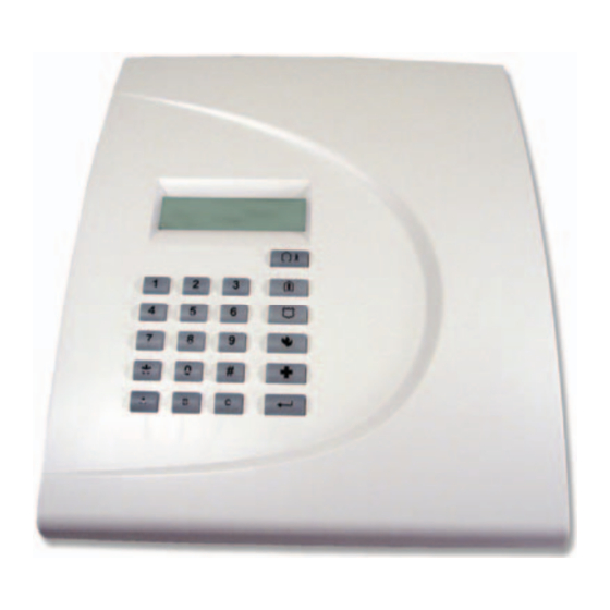
- Page 1 ICP-VR8488 Quick Reference Guide Intruder Alarm System...
-
Page 2: Copyright Notice
Bosch. material. Except as specified above or where authorized by the Bosch Security Systems, Inc. reserves the right to Copyright Act 1968 (Cth), no part of this publication make changes to features and specifications of its may be reproduced, transmitted, modified or stored, products at any time without prior notification. -
Page 3: Table Of Contents
8.14.1 Add a User Code ...........15 Keyswitch Zone Options ..........20 8.14.2 Delete a User Code........15 Swinger Shutdown Count for Siren ......20 8.15 Change Domestic Telephone Numbers ..15 Swinger Shutdown Count for Dialer......20 Bosch Security Systems, Inc. | 12/08 | F01U089640-01... - Page 4 Delay Alarm Report Time...........25 Sensor Watch Time............25 Codepad Lockout Time..........25 Siren Run Time ............25 Siren Sound Rate............25 Auto Arming Pre-Alert Time ........25 Auto Arming Time............25 Auto Disarming Time ..........25 Kiss-Off Wait Time ............25 Bosch Security Systems, Inc. | 12/08 | F01U089640-01...
-
Page 5: Icp-Vr8488 | Quick Reference Guide | En
Table 1: Keypad Indicator States ......12 Table 2: Location 177 Programming Option Bits14 Table 3: Telephone Monitor Mode Zone LEDs.15 Table 4: Fault Indicators........16 Table 5: Hexadecimal Values for Zone Nos..27 Bosch Security Systems, Inc. | 12/08 | F01U089640-01... -
Page 6: Figure 1: Opening The Cover
• Automatic Call Forward On and Off 3.0 Installation 1. At the rear of the ICP-VR8488, insert a flat bladed screwdriver into the slot between the base and top cover as shown in Figure 1 on page 6. Bosch Security Systems, Inc. | 12/08 | F01U089640-01... -
Page 7: Figure 3: Rf Receiver Data Cable
3 – DC siren Figure 4: Removing the RF Receiver 8. Press the latch away from the ICP-VR8488 PCB and remove the PCB from the case. 9. Insert the telephone lead through the entry hole shown in Figure 6 on page 7 and route the telephone lead as shown in Figure 7 on page 8. -
Page 8: Figure 7: Telephone Lead
10. Push the AC MAINS lead through the hole as shown in Figure 6 on page 7. 1 – Rubber feet If you are mounting the ICP-VR8488 on the wall, do 13. Connect the telephone lead to the telephone Step 11. If not, do Step 12. -
Page 9: Rf Receiver Interface Connections
ICP-VR8488 PCB to the + and — terminals, respectively, on the battery. 20. Install the cover on the ICP-VR8488. 21. Connect power to the ICP-VR8488 using the AC plug pack (TF008). 22. Enter the factory default code (2580) for User 1 and press [#] to reset any alarm that might occur upon system power up. -
Page 10: Diagrams
ICP-VR8488 | Quick Reference Guide | 5.0 Diagrams EN | 10 5.0 Diagrams Figure 14: Wiring Diagram 1 – 605 plug 7 – Power to external equipment: 15 – Strobe 12 V @ 400 mA 2 – 6 (Red) Telecom line (street) 16 –... -
Page 11: Figure 15: Icp-Cc488 Component Overlay
ICP-VR8488 | Quick Reference Guide | 5.0 Diagrams EN | 11 Figure 15: ICP-CC488 Component Overlay 1 – Socket for telecom lead connect 6 – Battery input 2 – Termination for phone line 7 – Plug pack input (Bosch TF008) OUT –... -
Page 12: Getting To Know The Icp-Vr8488
STAY status of the device changes from normal to faulted. Mode. If a detection device faults when the ICP-VR8488 is On – AC MAINS supply is normal. Flashing (with Service indicator) – AC armed (AWAY Mode or STAY Mode), the Power MAINS supply failure. -
Page 13: Stay Indicator
5 – Arm and Disarm buttons: Press both buttons memory. Alarm memory is cleared the next time at same time for 2 sec to send a Panic alarm you arm your system by turning the ICP-VR8488 on The system can be programmed so that a and off again. -
Page 14: Programming Option Bit Locations
Adding RF Keyfobs Example The ICP-VR8488 supports a total of 16 users. Users If at Location 177 you only want options 1, 2, and 4, 1 to 8 are assigned as PIN codes and Users 9 to 16 add the numbers together and the total is the are assigned as remote radio RF codes. -
Page 15: Stay Mode 1
ICP-VR8488 | Quick Reference Guide | 8.0 Using the System EN | 15 2. To send a Test Report, press and hold [9] until 8.6.2 STAY Mode 1 two beeps sound. Press and hold [*] until two beeps sound. 3. When complete, repeat Step 1 to toggle Telephone Monitor Mode off. -
Page 16: Toggle Day Alarm On/Off
ICP-VR8488 | Quick Reference Guide | 8.0 Using the System EN | 16 3. Repeat Step 2 to select another zone to be 8.18 Toggle Day Alarm On/Off automatically isolated when armed in STAY Press and hold [4] until two beeps sound. -
Page 17: Programming Guide
ICP-VR8488 | Quick Reference Guide | 9.0 Programming Guide EN | 17 9.0 Programming Guide Phone Number 2 - Receiver 2 Location 056 to 071 Default Shaded options indicate default values. 0 = 10 and telephone termination = 0 Anywhere else 0 = 0... -
Page 18: Telephone Line Fail Options
ICP-VR8488 | Quick Reference Guide | 9.0 Programming Guide EN | 18 Telephone Line Fail Options Installer Code Location Location 181 to 184 Default Location Default Display FAULT indicator when telephone line fails Sound alarm when system arms Sound alarm when system disarms... -
Page 19: User Code Authority Levels
ICP-VR8488 | Quick Reference Guide | 9.0 Programming Guide EN | 19 User Code Authority Levels Zone Defaults 267 to 322 Priority Description Location Location Default Arm/disarm Zone #01 (Default = Delay-1) Arm only Zone Type Arm/disarm and Open/Close Reports... -
Page 20: Icp-Vr8488 | Quick Reference Guide
ICP-VR8488 | Quick Reference Guide | 9.0 Programming Guide EN | 20 Location 309 to 322 (continued) Zone Options 1 Zone #07 (Default = Instant) Option Description Zone Type Lockout siren/dialer Zone Pulse Count Delay Alarm Report Zone Pulse Count Time... -
Page 21: Zone Status - Zone Tamper Report
ICP-VR8488 | Quick Reference Guide | 9.0 Programming Guide EN | 21 Zone Status – Zone Tamper Report RF Receiver Trouble Report Location 381 to 382 396 to 397 Location Location Default Location Default Zone Tamper Report RF Receiver Trouble Report... -
Page 22: Codepad Reporting Options
ICP-VR8488 | Quick Reference Guide | 9.0 Programming Guide EN | 22 Codepad Reporting Options Test Report Time (Automatic) 428 to 434 Location Location No Codepad Alarm Reports allowed Location Default Report to Receiver 1 Hour of day (tens digit) -
Page 23: Outputs
ICP-VR8488 | Quick Reference Guide | 9.0 Programming Guide EN | 23 Outputs Event Codes Location 436 to 465 Event Description Code Location Default EDMSAT – satellite siren (Output 1 only) Output 1 (Default = Horn speaker) System armed Event Code... -
Page 24: Event Codes
ICP-VR8488 | Quick Reference Guide | 9.0 Programming Guide EN | 24 Event Codes (continued) Polarity (Modes) Event Description Option Description Code Output not used Codepad Panic (multibreak) v1.05+ Normally open, going low Mimic zone 1 Normally open, pulsing low... -
Page 25: Exit Time (Away/Stay Modes)
ICP-VR8488 | Quick Reference Guide | 9.0 Programming Guide EN | 25 Exit Time (AWAY/STAY Modes) Auto Arming Time Location 470 to 471 Location 482 to 485 Location Default Location Default Increments of 1 sec Hour of the day (tens digit) -
Page 26: Consumer Options 1
ICP-VR8488 | Quick Reference Guide | 9.0 Programming Guide EN | 26 Consumer Options 1 Domestic Telephone Numbers Location Location 550 to 597 Default Default None Test reports only when armed Reserved Test report after siren reset Location Auto arm in STAY Mode 1... -
Page 27: Rf Device Mapping For Devices 1 To 8
ICP-VR8488 | Quick Reference Guide | 9.0 Programming Guide EN | 27 Country Codes RF Device Mapping for Devices 1 to 8 838 to 839 Refer to page 28 Location 616 to 623 Location Location Default Location Default Value* Country Code (tens digit) -
Page 28: 10.0 Country Codes
ICP-VR8488 | Quick Reference Guide | 10.0 Country Codes EN | 28 10.0 Country Codes Country Code Country Code Country Code Country Code Country Code Argentina Poland Liechtenstein Gabon Papua New Guinea Australia Portugal Gambia Paraguay Austria Romania Afghanistan Ghana... - Page 29 ICP-VR8488 | Quick Reference Guide | 10.0 Country Codes EN | 29 Country Code Country Code Country Code Country Code Country Code Nigeria French Equatorial G Nicaragua Polynesia uinea Norway Iceland Eritrea Niger Peru Israel Ethiopia Palau Philippines Lebanon Fiji Panama Bosch Security Systems, Inc.
- Page 30 ICP-VR8488 | Quick Reference Guide | Notes EN | 30 Notes Bosch Security Systems, Inc. | 12/08 | F01U089640-01...
- Page 31 ICP-VR8488 | Quick Reference Guide | Notes EN | 31 Notes Bosch Security Systems, Inc. | 12/08 | F01U089640-01...
- Page 32 Bosch Security Systems, Inc. 130 Perinton Parkway Fairport, NY 14450-9199 USA www.boschsecurity.com © 2008 Bosch Security Systems, Inc. F01U089640-01...
Need help?
Do you have a question about the ICP-VR8488 and is the answer not in the manual?
Questions and answers