Table of Contents
Advertisement
Quick Links
1702595G10/G20
1702595G12
1702595G14
1702595G16
1700530F1
1700532F1
1700533F1
1700534F1
61702595G10-34C
October 2013
NetVanta 1535P
ActivReach Ethernet Switch
Hardware Installation Guide
NetVanta 1535P
NetVanta ActivReach Media Converter
Hydra Interconnect Cable
NetVanta ActivReach Ethernet Port
Protection Device
NetVanta 1131 RPS/EPS
NetVanta 1131 RPS Cable
NetVanta 1131 EPS Cable
NetVanta 1131 Dual Mounting Tray
Advertisement
Table of Contents

Related Manuals for ADTRAN NetVanta 1535P


Summary of Contents for ADTRAN NetVanta 1535P
- Page 1 NetVanta 1535P ActivReach Ethernet Switch Hardware Installation Guide 1702595G10/G20 NetVanta 1535P 1702595G12 NetVanta ActivReach Media Converter 1702595G14 Hydra Interconnect Cable 1702595G16 NetVanta ActivReach Ethernet Port Protection Device 1700530F1 NetVanta 1131 RPS/EPS 1700532F1 NetVanta 1131 RPS Cable 1700533F1 NetVanta 1131 EPS Cable...
- Page 2 To the Holder of the Manual The contents of this manual are current as of the date of publication. ADTRAN reserves the right to change the contents without prior notice. In no event will ADTRAN be liable for any special, incidental, or consequential damages or for commercial losses even if ADTRAN has been advised thereof as a result of issue of this publication.
- Page 3 NetVanta 1535P Hardware Installation Guide Conventions Conventions Notes provide additional useful information. Cautions signify information that could prevent service interruption or damage to the equipment. Warnings provide information that could prevent injury or endangerment to human life. 61702595G10-34C Copyright © 2013 ADTRAN, Inc.
- Page 4 Safety Instructions NetVanta 1535P Hardware Installation Guide Safety Instructions When using your telephone equipment, please follow these basic safety precautions to reduce the risk of fire, electrical shock, or personal injury: 1. Do not use this product near water, such as a bathtub, wash bowl, kitchen sink, laundry tub, in a wet basement, or near a swimming pool.
- Page 5 Denial of Service (DoS) attacks, loss or theft of data, and the unauthorized or illegal use of said equipment. ADTRAN OFFERS NO WARRANTIES, EITHER EXPRESSED OR IMPLIED, REGARDING THE PREVENTION, DETECTION, OR DETERRENCE OF TOLL FRAUD, NETWORKING ATTACKS, OR UNAUTHORIZED, ILLEGAL, OR IMPROPER USE OF ADTRAN EQUIPMENT OR SOFTWARE.
- Page 6 Service and Warranty NetVanta 1535P Hardware Installation Guide Copyright © 2013 ADTRAN, Inc. 61702595G10-34C...
-
Page 7: Table Of Contents
NetVanta 1535P ........ - Page 8 Table of Contents NetVanta 1535P Hardware Installation Guide Copyright © 2013 ADTRAN, Inc. 61702595G10-34C...
- Page 9 NetVanta 1535P Rear Panel Layout ......... . . 17 Figure 3. NetVanta 1535P ActivReach Switch Wallmount Installation ......24 Figure 4.
- Page 10 List of Figures NetVanta 1535P Hardware Installation Guide Copyright © 2013 ADTRAN, Inc. 61702595G10-34C...
- Page 11 Table A-3. SFP Slot Pinouts ............40 Table A-4. 50-Pin Champ Connector Pinouts for Hydra Interconnect Cable..... . 41 61702595G10-34C Copyright © 2013 ADTRAN, Inc.
- Page 12 List of Tables NetVanta 1535P Hardware Installation Guide Copyright © 2013 ADTRAN, Inc. 61702595G10-34C...
-
Page 13: Introduction
INTRODUCTION This hardware installation guide describes the NetVanta 1535P ActivReach Ethernet unit’s physical characteristics, lists its features and specifications, introduces basic functionality, and provides installation instructions. • Physical Descriptions on page 14 • Product Specifications on page 19 • Unit Installation on page 21 •... -
Page 14: Physical Descriptions
Extended Power Supply The NetVanta 1535P unit also provides a connection for an optional EPS on the rear panel. The NetVanta 1131 RPS/EPS (P/N 1700530F1) is sold separately. In the event that the internal power supply fails, the EPS will provide up to 370 W of power for PoE applications. -
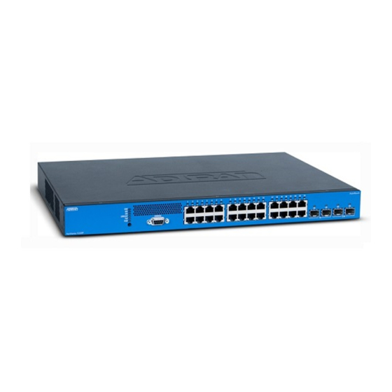
Page 15: Figure 1. Netvanta 1535P Front Panel Layout
Physical Descriptions Power over Ethernet The NetVanta 1535P provides the ability to detect attached powered devices (PDs) and deliver power to the PD via existing Ethernet cabling. The NetVanta 1535P is fully compliant with the IEEE 802.3af PoE standard. By default, the PoE switches discover and provide power to IEEE-compliant PDs. - Page 16 Physical Descriptions NetVanta 1535P Hardware Installation Guide Extended Power Supply LED The EPS LED is located on the left side of the unit and indicates when the unit is receiving power from the EPS. Link/Activity LED The LINK/ACT LED is located on the left side of the unit and indicates that the port LEDs are displaying link/activity status.
-
Page 17: Figure 2. Netvanta 1535P Rear Panel Layout
NetVanta 1535P Hardware Installation Guide Physical Descriptions NetVanta 1535P Rear Panel Design The NetVanta 1535P rear panel is shown below. AC INPUT RPS - 12VDC EPS - 50VDC Figure 2. NetVanta 1535P Rear Panel Layout Rear Panel Interfaces The rear panel has a power input to a +12 VDC RPS. The RPS LED, located on the front panel of the unit, indicates when the unit is being powered from the RPS. -
Page 18: Led Descriptions
Physical Descriptions NetVanta 1535P Hardware Installation Guide LED Descriptions The following table describes LED activity. Table 1. Front Panel LED Descriptions Color Indication STAT Unit is not receiving power. Green (flashing) On power up, the STAT LED flashes rapidly for five seconds, during which time the user may escape to boot mode from the CONSOLE port. -
Page 19: Product Specifications
NetVanta 1535P Hardware Installation Guide Product Specifications PRODUCT SPECIFICATIONS Physical Interface Ethernet Ports • 24 standard 10/100/1000Base-T interfaces plus ADTRAN’s ActivReach Ethernet capability • 4 SFP interfaces • Autorate/duplex/MDI/MDI-X Console Port • DB-9, EIA-232 Switching • Layer 3 Lite switching capability •... - Page 20 Product Specifications NetVanta 1535P Hardware Installation Guide VLAN Support • Port-based virtual local area networks (VLANs) • 802.1Q tagged trunked VLANs • Support for up to 255 active VLANs Storm Control • Broadcast, unicast, and multicast Administration • Familiar CLI •...
-
Page 21: Unit Installation
To prevent electrical shock, do not install equipment in a wet location or during a lightning storm. • The NetVanta 1535P is intended to be installed, maintained, and serviced by qualified service personnel only and should be installed in a restricted access location as described in UL/IEC 60950-1. -
Page 22: Tools Required
Rack Mounting the NetVanta 1535P The NetVanta 1535P are 1U-high, rack-mountable units that can be installed into a 19-inch equipment rack with the mounting brackets that are shipped with the units. The following steps guide you in mounting the NetVanta into a rack. - Page 23 25). Wall Mounting the NetVanta 1535P Units By following these instructions exactly, the NetVanta 1535P units can be safely mounted on the wall. For instructions on wall mounting the NetVanta 1535P unit, see the table and Figure 3 on page •...
-
Page 24: Figure 3. Netvanta 1535P Activreach Switch Wallmount Installation
Reattach the mounting brackets to the chassis (see Figure Decide on a location for the NetVanta. The NetVanta 1535P ActivReach switch is mounted with the front panel facing down as shown in Figure 3. -
Page 25: Rj-45 Pinouts For Activreach
Supplying Power to the Unit The NetVanta 1535P, units come equipped with an auto-sensing 100 to 250 VAC, 50/60 Hz power supply for connecting to a properly grounded power receptacle. All necessary power cords are shipped with the units. To power these units, connect the power cable to an appropriate AC power source. -
Page 26: Installing A Netvanta Activreach Media Converter
10/100Base-T Ethernet over varying cable types and cable distances well beyond the standard Ethernet limitation of 100 meters. It has no input power supply. It draws power from the upstream NetVanta 1535P ActivReach Ethernet Switch. The ActivReach Media Converter has two RJ-45 connectors (labeled IN and OUT) with built-in LEDs. - Page 27 Physical • Dimensions: 3.50-inch W x 2.00-inch H x 1.12-inch D NetVanta ActivReach Media Converter intended for use only with the NetVanta 1535P ActivReach Ethernet Switch (P/N 1702595G10). • The NetVanta ActivReach Media Converter is intended for intrabuilding use only.
-
Page 28: Table 2. Netvanta Activreach Media Converter Led Descriptions
OFF to terminate the PoE from the NetVanta 1535P. Ensure that the plugs on each end of the network cables have the two center pins connected. The center pins are used to transmit ActivReach PoE from the NetVanta 1535P to the Media Converter. -
Page 29: Netvanta 1131 Rps/Eps
After unpacking the unit, inspect it for possible shipping damage. If the equipment has been damaged in transit, immediately file a claim with the carrier and contact ADTRAN Customer Service (refer to the Support page on the ADTRAN website at http://www.adtran.com/support). -
Page 30: Netvanta 1131 Front Panel Design
NetVanta 1131 RPS/EPS NetVanta 1535P Hardware Installation Guide NetVanta 1131 Front Panel Design The NetVanta 1131 front panel is shown below. Table 3 on page 31 describes all of the LED behaviors. EPS CONN CONN RPS1 STAT POWER CONN RPS2... -
Page 31: Led Behaviors
NetVanta 1535P Hardware Installation Guide NetVanta 1131 RPS/EPS Rear Panel Interfaces Power Connection The NetVanta 1131 has a power input (labeled POWER) to the AC universal power supply. Refer Powering the NetVanta 1131 and the NetVanta Switch on page 37 for connection details. -
Page 32: Installing The Netvanta 1131 Rps/Eps
NetVanta 1131 RPS/EPS NetVanta 1535P Hardware Installation Guide Installing the NetVanta 1131 RPS/EPS The instructions and guidelines provided in the following sections cover hardware installation topics, such as mounting options and supplying power to the NetVanta 1131. Rack Mounting the NetVanta 1131 The NetVanta 1131 can be installed into a 19-inch equipment rack by following these steps: •... -
Page 33: Figure 8. Rack Mounting The Netvanta 1131 Using The Brackets
NetVanta 1535P Hardware Installation Guide NetVanta 1131 RPS/EPS Single Rackmount Instructions for Rack Mounting the NetVanta 1131 (Single Mount) Step Action Securely fasten the rackmount brackets to the NetVanta 1131 using the screws provided with the unit. The brackets can be attached in flush mount, 2-inch mount, and mid-mount positions... -
Page 34: Figure 9. Rack Mounting The Netvanta 1131 Using The Dual Mounting Tray
NetVanta 1131 RPS/EPS NetVanta 1535P Hardware Installation Guide Dual Rackmount Instructions for Rack Mounting the NetVanta 1131 (Dual Mount) Step Action Install the dual mounting tray (P/N 1700534F1 purchased separately) in a stationary equipment rack using the mounting brackets and four screws provided. -
Page 35: Wall Mounting The Netvanta 1131
NetVanta 1535P Hardware Installation Guide NetVanta 1131 RPS/EPS Wall Mounting the NetVanta 1131 The NetVanta 1131 can be mounted on a wall by following these steps: Instructions for Wall Mounting the NetVanta 1131 Step Action Attach the wallmount brackets so that the portion with the mounting holes is flush with the bottom of the chassis. -
Page 36: Connecting The Netvanta 1131 And The Netvanta Switch
NetVanta 1131 RPS/EPS NetVanta 1535P Hardware Installation Guide Connecting the NetVanta 1131 and the NetVanta Switch Follow these instructions to connect your NetVanta 1131 RPS/EPS to your NetVanta switch Instructions for Connecting the NetVanta 1131 to the NetVanta Switch Step... -
Page 37: Powering The Netvanta 1131 And The Netvanta Switch
ADTRAN Support Community. For details on the command line interface (CLI), refer to the AOS Command Reference Guide. All other related documents are also available online at http://supportforums.adtran.com. 61702595G10-34C Copyright © 2013 ADTRAN, Inc. - Page 38 NetVanta 1131 RPS/EPS NetVanta 1535P Hardware Installation Guide Copyright © 2013 ADTRAN, Inc. 61702595G10-34C...
-
Page 39: Appendix A. Connector Pin Definitions
Unused Table A-2. 1000Base-T Gigabit Ethernet Port Pinouts Name Description TRD0+ Transmit/Receive Positive TRD0- Transmit/Receive Negative TRD1+ Transmit/Receive Positive TRD2+ Transmit/Receive Positive TRD2- Transmit/Receive Negative TRD1- Transmit/Receive Negative TRD3+ Transmit/Receive Positive TRD3- Transmit/Receive Negative 61702595G10-34C Copyright © 2013 ADTRAN, Inc. -
Page 40: Table A-3. Sfp Slot Pinouts
Appendix A. Connector Pin Definitions NetVanta 1535P Hardware Installation Guide Table A-3. SFP Slot Pinouts Name Name TX_FAULT RX_DAT- TX_DISABLE RX_DAT+ I2C_SDA I2C_SCL VddR MOD_DEF(0) VddT RATESEL RX_LOS TX_DAT+ TX_DAT- Copyright © 2013 ADTRAN, Inc. 61702595G10-34C... -
Page 41: Table A-4. 50-Pin Champ Connector Pinouts For Hydra Interconnect Cable
NetVanta 1535P Hardware Installation Guide Appendix A. Connector Pin Definitions Table A-4. 50-Pin Champ Connector Pinouts for Hydra Interconnect Cable Color Port Color Blue / White White / Blue Orange / White White / Orange Green / White White / Green... - Page 42 Appendix A. Connector Pin Definitions NetVanta 1535P Hardware Installation Guide Copyright © 2013 ADTRAN, Inc. 61702595G10-34C...
Need help?
Do you have a question about the NetVanta 1535P and is the answer not in the manual?
Questions and answers