Table of Contents
Advertisement
Quick Links
Advertisement
Table of Contents

Subscribe to Our Youtube Channel
Related Manuals for ADTRAN NetVanta 3148 Series


Summary of Contents for ADTRAN NetVanta 3148 Series
- Page 1 NetVanta 3148/4148 Series Fixed Port Secure Access Routers Hardware Installation Guide 17003148F1 NetVanta 3148 Chassis 17003148F11 NetVanta 3148 PoE Chassis 17004148F1 NetVanta 4148 Chassis 17004148F11 NetVanta 4148 PoE Chassis 617004148F1-34B August 2020...
- Page 2 To the Holder of the Manual The contents of this manual are current as of the date of publication. ADTRAN reserves the right to change the contents without prior notice. In no event will ADTRAN be liable for any special, incidental, or consequential damages or for commercial losses even if ADTRAN has been advised thereof as a result of issue of this publication.
- Page 3 NetVanta 3148/4148 Series Hardware Installation Guide Conventions Conventions Notes provide additional useful information. Cautions signify information that could prevent service interruption or damage to the equipment. Warnings provide information that could prevent injury or endangerment to human life. 617004148F1-34B Copyright © 2020 ADTRAN, Inc.
- Page 4 • Il n’existe aucune pièce pouvant être réparée par l’utilisateur à l’intérieur de cet équipement This product meets EU RoHS Directive. Refer to www.adtran.com for further information on RoHS and Waste Electrical and Electronic Equipment (WEEE) safety guidelines. Save These Important Safety Instructions Copyright © 2020 ADTRAN, Inc. 617004148F1-34B...
- Page 5 2. This device must accept any interference received, including interference that may cause undesired operation. Changes or modifications not expressly approved by ADTRAN could void the user’s authority to operate this equipment. • This equipment has been tested and found to comply with the limits for a Class A digital device, pursuant to part 15 of the FCC Rules.
-
Page 6: Table Of Contents
Installing SFP Modules in the Unit ........... 21 Copyright © 2020 ADTRAN, Inc. - Page 7 Wallmount Installation ............20 617004148F1-34B Copyright © 2020 ADTRAN, Inc.
- Page 8 USB Port Pinouts ............23 Copyright © 2020 ADTRAN, Inc.
-
Page 9: Introduction
The NetVanta 3148/4148 Series has two small form-factor pluggable (SFP) slots that accept a number of industry standard SFP modules. The SFP modules provide Gigabit Ethernet fiber connectivity for high-speed uplinks. For a list of supported SFP modules, visit the ADTRAN website at http://www.adtran.com. -
Page 10: Shipping Contents
After unpacking the unit, inspect it for possible shipping damage. If the equipment has been damaged in transit, immediately file a claim with the carrier and contact ADTRAN Customer Service (refer to the page on the ADTRAN website at http://www.adtran.com/support). -
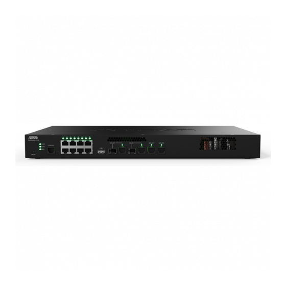
Page 11: Figure 2. Netvanta 3148/4148 Front Panel Layout (Poe)
The status LEDs are located above each interface. 2 Routed 10/100/1000Base-T Copper Ethernet Interfaces The Gigabit Ethernet ports ( ) consist of one RJ-45 connector for copper GIG 0/3 GIG 0/4 connections. The status LED is located above the interface. 617004148F1-34B Copyright © 2020 ADTRAN, Inc. -
Page 12: Netvanta 3148/4148 Series Rear Panel Design
The port has activity (transmit or receive). SWITCH The port is not delivering power. (1 through 8, when Green (solid) The port is delivering power. PoE MODE is ON) Red (solid) The port has detected a PoE fault. Copyright © 2020 ADTRAN, Inc. 617004148F1-34B... -
Page 13: Features And Specifications
RIP (v1 and v2) • • IGMP v2 • Layer 3 Backup • Multi-VRF CE • • PAP and CHAP • Multihoming • VRRP • LLDP/LLDP-MED Management and Utilities • Auto-Configuration • AOS command line interface (CLI) 617004148F1-34B Copyright © 2020 ADTRAN, Inc. -
Page 14: Security
Network address translation (NAT) (1:1, many:1) and 1:1 port translation • NAT-compatible SIP ALG Secure Management • Multi-level access control • TACACS+ • RADIUS AAA • SSH CLI and SSL GUI Content Filtering • Inherent URL filter • Top website reports Copyright © 2020 ADTRAN, Inc. 617004148F1-34B... -
Page 15: Ethernet Features
Input Voltage: 110-240 VAC, 50/60 Hz Agency Approvals • FCC Part 15, Class A • NRTL Safety Listed • IEC/EN 62368-1 • AS/NZS 60950.1/62368.1 • CE Mark • ETSI 300 019 • RoHS • ITU-T K.21 617004148F1-34B Copyright © 2020 ADTRAN, Inc. -
Page 16: Unit Installation
•ADTRAN's Ethernet Port Protection Device (EPPD) (P/N 1700502G1) must be connected between the unit and the outside plant cable. Use of any Ethernet protector other than ADTRAN's for this purpose will void the user's warranty. •ADTRAN's NetVanta PoE Protector/Injector (P/N 1702595F15) must be connected between the unit and the outside plant cable. -
Page 17: Equipment Required
•Le protecteur / injecteur NetVanta PoE d'ADTRAN (P/N 1702595F15) doit être connecté entre l'unité et le câble extérieur de l'installation. L'utilisation de tout protecteur PoE autre qu'ADTRAN à cette fin annulera la garantie de l'utilisateur. Electronic modules can be damaged by static electrical discharge. Before handling modules, put on an antistatic discharge wrist strap to prevent damage to electrical components. - Page 18 • Reliable grounding of rack-mounted equipment should be maintained. Particular attention should be given to supply connections other than direct connections to the branch circuit (e.g., use of power strips). Copyright © 2020 ADTRAN, Inc. 617004148F1-34B...
- Page 19 Have an assistant hold the unit in position as you install two #6 to #10 (1-inch or greater in length) wood screws through the unit’s brackets and into the mounted board (see Figure 4 on page 20). Proceed to the steps given in Supplying Power to the Unit on page 617004148F1-34B Copyright © 2020 ADTRAN, Inc.
-
Page 20: Supplying Power To The Unit
With the flat side up, fully insert the AC power cord into the AC power receptacle on the rear panel of the unit. Insert the other end of the power cable into a properly grounded power source. Confirm that the power is connected properly. The STAT LED should be ON. Copyright © 2020 ADTRAN, Inc. 617004148F1-34B... -
Page 21: Installing Sfp Modules In The Unit
ADTRAN Support Community. For details on the command line interface (CLI), refer to the Guide. All other related documents are also available online at https:// Command Reference supportcommunity.adtran.com. 617004148F1-34B Copyright © 2020 ADTRAN, Inc. -
Page 22: Table A-1. Copper Gigabit Ethernet Port Pinouts
RJ_SWP2_MDID_- Switch port 2 Media Dependent Interface D (-) Shield mounting pin (connected to ground (GND)) Shield mounting pin (connected to GND) Shield mounting pin (connected to GND) Shield mounting pin (connected to GND) Copyright © 2020 ADTRAN, Inc. 617004148F1-34B... -
Page 23: Table A-3. Console Port Pinouts
Table A-4. USB Port Pinouts Signal Description VBUS 5 V USB Bus supply USB 2.0 Data (-) USB 2.0 Data (+) SHIELD Connector shield (connected to ground (GND)) SHIELD Connector shield (connected to GND) 617004148F1-34B Copyright © 2020 ADTRAN, Inc.
Need help?
Do you have a question about the NetVanta 3148 Series and is the answer not in the manual?
Questions and answers