Table of Contents
Advertisement
Quick Links
Download this manual
See also:
User Manual
Advertisement
Table of Contents

Related Manuals for IWILL DJ800


Summary of Contents for IWILL DJ800
- Page 1 IWILL DJ800 Motherboard User’s Manual Version 1.1 FB25634000...
- Page 2 DJ800 Motherboard ________________________________________________________________ User’s Manual...
- Page 3 DJ800 Motherboard Disclaimer The manufacturer makes no representations or warranties regarding the contents of this manual and specifically disclaims any implied warranties of merchantability or fitness for any particular purpose. Furthermore, the manufacturer reserves the right to revise this publication or make changes in the specifications of the product described within it at any time without notice and without obligation to notify any person of such revision or change.
-
Page 4: Table Of Contents
Table of Contents 1: Overview ........………………….…………....1-1 Packing list………………………………………………………………………………..1-1 Getting Help………………………………………………………………………….…...1-5 DJ800 Specification ........……………………………..………..1-6 2: Components and Jumper setting ......……………………... 2-1 Mainboard Map ...............……..………………….. 2-2 Components List………………………………………………………………………….2-3 Jumper Setting……………………………………………………………………………2-4 Rear Panel I/O Panel.……………………………………………………..……………..2-7 Additional I/O Connectors…………………………………………………………...…2-9 EPS12V Power Connectors …………….....……………….………..2-14 Primary IDE Connectors……………………………………………………………….2-15... - Page 5 DJ800Motherboard 4: BIOS Setup ..........………………………... 4-1 Starting the BIOS Setup ........……………………..…………….4-2 Using the BIOS Setup Utility......…............4-4 Main Menu ........………………………………………….…..4-6 Advanced Menu .......…………………………........4-7 Boot Menu .......…………………………........4-8 Boot Setting Configuration Submenu ..………………………......4-9 Exit Menu………………………………………………………………………..……….4-11 5: OS and Drivers Installation ......……...……………... 5-1 OS Installation……………………………………………………….....….…………...5-2 Drivers Installation………………………………………………………….……………….5-3 ________________________________________________________________________...
-
Page 6: 1: Overview
Chapter 1 Overview Chapter 1 Overview ________________________________________________________________________ Overview... - Page 7 Package DJ800 Motherboard Three jumper caps (Extra caps in case original caps get lost) One Power Installation CD (contains drivers and utilities) DJ800 User’s manual Rear panel I/O shield Two sets of SATA cables One ATA-66/100 IDE cable One floppy disk drive cable...
- Page 8 DJ800 Motherboard YOU MUST HAVE ENOUGH SYSTEM INTEGRATION KNOWLEDGE BEFORE THE INSTALLATION ENERAL AFETY RECAUTIONS Keep the area around the Server clean and free of clutter. Servers weigh a lot. When lifting the system, two people should lift slowly from opposite ends with their feet spread out to distribute the weight.
- Page 9 Chapter 1 Overview Touch a grounded metal object before removing the board from the antistatic bag. Do not let components or PCBs come into contact with your clothing, which may retain a charge even if you are wearing a wrist strap. Handle a board by its edges only;...
-
Page 10: Getting Help
If those options don't work for you, IWILL also provides some helpful resources to help you. -
Page 11: Dj800 Specification
Chapter 1 Overview DJ800 S PECIFICATIONS Processor Intel® Dual Xeon Socket 604 CPUs Supports 800MHz FSB Chipset Intel E7525 Chipset MCH Intel ICH5R Intel PXH Winbond 83627 HF Memory 8 DIMMs for 240-pin DDR2 400 DIMM sockets Uses Registered DDR2 with ECC or Non-ECC memory... - Page 12 DJ800 Motherboard Internal I/O 34-pin Floppy Connector connector 4-pin CD-In and Aux-In audio input connector 2x 40-pin IDE connectors, supports up to four (4) Enhanced IDE devices IDE Bus Dual Channel Master Mode Ultra DMA 100/66/33 PS/2 mouse and keyboard connectors...
-
Page 13: 2: Components And Jumper Setting
Chapter 2 Hardware Installation Chapter 2 Components and Jumper Setting ____________________________________________________________________________________________________________ Hardware Installation... -
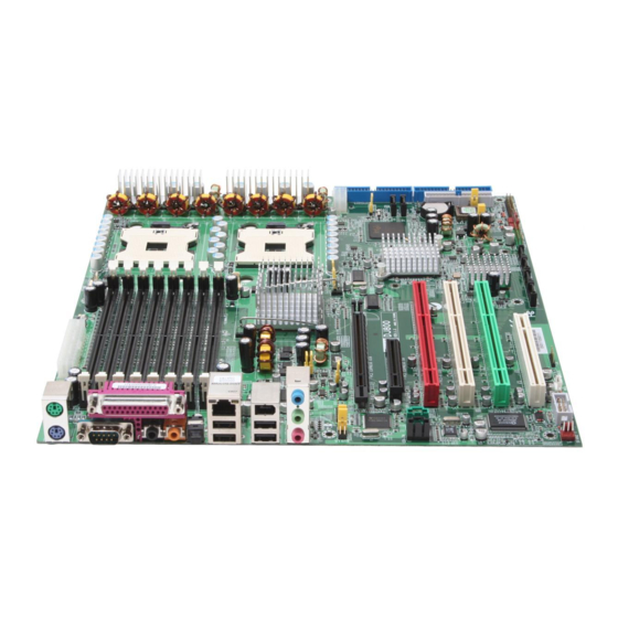
Page 14: Mainboard Map
DJ800 Motherboard AINBOARD ____________________________________________________________________________________________________________ Component and Jumper Setting... -
Page 15: Components List
Chapter 2 Component and Jumper Setting Components List CPU1; CPU2 Intel Xeon Socket604 Processor Primary; Secondary IDE Driver Connectors Floppy Floppy Disk Driver Connector PCI Slots PCI-Express x16, x4 Slots; PCI-X 100,133; PCI DIMM B4~A1 Memory Socket for DDR2 Memory Clear CMOS Header JP10 and JP10A Memory Voltage Select Jumper... -
Page 16: Jumper Setting
DJ800 Motherboard Jumper Setting JP1: Clear CMOS Header The onboard button cell battery powers the CMOS RAM. It contains all the BIOS setup information. Keep the jumper connected to pins 1-2 (Default) to retain the RTC data as shown below. - Page 17 Chapter 2 Component and Jumper Setting JP10 and JP10A: Memory Voltage Select Jumper This header lets you adjust the memory voltage. JP10A JP10 VDDR JP10 JP10A 1.8V 1.85V 1.9V 1.95V JP16: BIOS Flash Protect Jumper This jumper protects the system from unnecessary updating or flashing of the BIOS. It secures the BIOS therefore prevents accidental overwriting of the data stored in flash memory.
- Page 18 DJ800 Motherboard JP19: LAN Power Select Jumper This header lets you set your LAN connectors power status. You can choose power standby or not. VCC33 Stand By VCC33 J57: Front Audio Jumper This header lets you enable or disable the function of the front audio connector.
- Page 19 Chapter 2 Component and Jumper Setting I/O P ANEL ORTS This is an illustration of the Mainboard rear I/O port array PS/2 Mouse Connector (6-pin Female) The system will direct IRQ12 to the PS/2 mouse if one is detected. If no mouse is detected, IRQ12 will be free for expansion cards to use.
- Page 20 The interface is supported by the onboard Analog Device AD1980. It has 3 phone jacks for Line-Out, Microphone In, and Line-In. S/PDIF Port DJ800 also provides the S/PDIF out, Rear Out, and Center Out function. ________________________________________________________________________ Component and Jumper Setting...
-
Page 21: Additional I/O Connectors
Chapter 2 Component and Jumper Setting I/O C DDITIONAL ONNECTORS The Mainboard also contains connectors for adding additional ports and devices to the Mainboard. J43: Front Panel Switch Header - HDD + Reset button -ACPI+ - SPEAKER + - Power LED Reset Button (2-pin RST) This 2-pin connector connects to the chassis-mounted reset switch for rebooting your computer without turning your power switch off and on. - Page 22 DJ800 Motherboard Power On Switch This switch connects to the system’s Power button allowing you to power on and off the system. You can configure the system to use the keyboard or mouse to power-on the system. You can also configure the system to respond to power restoration after a power outage occurs.
- Page 23 Chapter 2 Component and Jumper Setting J46: WOL Connector Function This connector lets you attach a managed network adapter to the motherboard via a Wake-on-LAN cable. When the system is off, the managed network adapter uses an alternate power source to monitor the network. If it receives a wake-up packet from the server the system is remotely and automatically powered up.
- Page 24 DJ800 Motherboard J66, J67, J68, J69 Serial ATA Connector DJ800 supports up to 6 SATA devices each with data at transfer rates of 150MB/s. Two Serial ATA ports supported by ICH5R, and four Serial ATA ports supported by Marvell chipset. Marvell chipset also supports RAID configurations. RAID stands for "Redundant Array of Independent Devices"...
- Page 25 J34 &J34A: USB 2.0 P ORTS AND EADER DJ800 supports eight USB 2.0 ports. USB 2.0 supports transfer rates of up to 480MB/s. Four ports show up on the on-board I/O array, and four ports are internal. Pin Assignment Pin 1 VCC 5V Pin 2 VCC 5V...
-
Page 26: Eps12V Power Connectors
There are two power connectors on the motherboard of the required EPS 12V power supply. These are not standard ATX connectors. DJ800 needs a minimum 460-watt EPS 12V power supply that complies with the Intel Xeon processor power supply design guidelines. -
Page 27: Primary Ide Connectors
Chapter 2 Component and Jumper Setting RIMARY CONNECTORS The two 40-pin IDE connectors (primary and secondary channels) support 80-conductor IDE ribbon cables. Connect the single connector end to the Mainboard. Then, connect the two connectors at the other end to your IDE device(s). If you connect two hard disks to the same cable, you must set the second drive as a Slave through its jumper settings. - Page 28 DJ800 Motherboard CPU/ S YSTEM ONNECTORS There are five 3-pin fan connectors in the Mainboard. Two fans are used for CPU1 and CPU2; three fans are for system and front. These connectors support cooling fans of 500mA (6W) or less. Depending on the fan manufacturer, the wiring and plug may be different.
-
Page 29: 3: Hardware Installation
Chapter 3 Hardware Installation Chapter 3 Hardware Installation ________________________________________________________________________ Hardware Installation... -
Page 30: Motherboard Installation
DJ800 Motherboard Motherboard Installation This section explains the basic requirements for installing the motherboard in a system housing or “chassis”. Since housing designs vary widely, you will need to consult the housing documentation for specific information. To install the motherboard in a system housing, you will need to do the following: •... -
Page 31: Installing The Cpu And Heatsink Procedures
DJ800 Motherboard Installing the CPU and Heatsink Procedures IWILL DJ800 support Intel Xeon @FSB800 MHz processor. We only recommend using the Intel Original heatsink kit. CEK (Common Enabling Kit) is specially designed for the Intel latest Xeon. For installing CEK, please follow direction as below. - Page 32 Chapter 3 Hardware Installation Step 3-- Align the processor to the socket by matching the Pin 1 corner of the socket (marked with a triangle) to the Pin 1 corner on the Socket 604 (marked by a triangular hole in the Pin 1 corner). Align the Pin 1 corners Step 4-- Carefully insert the Xeon processor in the socket receptacles, taking care not to bend any pins.
- Page 33 Chapter 3 Hardware Installation Step 5-- Lower the locking mechanism’s retaining lever and secure it in place to secure the processor in the socket. Grasp the processor by the edges and gently pull upwards to insure it is properly inserted. The processor shouldn’t move. Secure the CPU retaining lever Step 6--Apply all of the TIM in the applicator to the center of the square heat...
- Page 34 Notice: If you use the third party heaksink, it would possibly not fit our Spring installation method. Please contact with your vendor for the further information, and also check on IWILL website. ________________________________________________________________________ Hardware Installation...
-
Page 35: Memory Installation Procedure
This Mainboard uses Registered DDR2 Memory with ECC or Non-ECC only. Please be aware of the difference between DDR and DDR2. DDR modules will NOT compatible with DDR2 slots. Don’t plug DDR modules into DJ800 memory slots. IMPORTANT Before buying DDR2 (Double Data Rate 2) DIMMs for use with the Mainboard, it is recommended that you consult your local reseller for the best and most compatible memory to use. - Page 36 Chapter 3 Hardware Installation ECOMMENDED EMORY ONFIGURATIONS The following steps are our recommended DIMM installation path based on the number of DIMMS being installed (Remember to check that the DIMMS are 1.8V Registered ECC or Non-ECC DDR2 DIMMs) Memory Installation Procedures 1.
-
Page 37: Installing Expansion Cards
Failure to do so may cause severe damage to both your Mainboard and expansion cards. Important: DJ800 provides a PCI-Express x16 slot for graphic use. It provides the higher performance and greater bandwidth. DJ800 does not support AGP slot, so please choose the graphic card with PCI-Express interface. -
Page 38: Powering On Your System
DJ800 Motherboard OWERING ON YOUR YSTEM Follow these instructions to power on the computer after you have installed the Mainboard and all system devices. 1. Be sure that all switches are off (in some systems, Off is marked by “O”). - Page 39 DJ800Motherboard Chapter 4 BIOS Setup ________________________________________________________________________ BIOS Setup...
-
Page 40: 4: Bios Setup
Chapter 4 BIOS Setup BIOS Setup This chapter discusses the AMIBIOS Setup program built into the ROM BIOS. The Setup program allows users to modify the basic system configuration. The BIOS is the Basic Input / Output System used in all IBM PC, XT, AT, and PS/2 compatible computers. - Page 41 Chapter 4 BIOS Setup As the memory is being tested, you can access the BIOS Setup Utility by pressing the <F2> key when “Press < F2> to enter SETUP” appears briefly at the bottom of the screen. From the main menu of the BIOS Setup Utility, you can access the other setup screens, such as the Security and Power menus.
-
Page 42: Using The Bios Setup Utility
DJ800Motherboard BIOS S SING THE ETUP TILITY Navigating through the BIOS Setup Utility is straightforward. Use the arrow keys to highlight items, press <Enter> to select items in menus, and press <Esc> to quit. The following table provides more details about how to navigate in the Setup program using the keyboard. - Page 43 DJ800Motherboard IMPORTANT The BIOS does NOT automatically save values that you have modified. If you do not save your values before you exit the BIOS Setup Utility, all your changes will be lost. If after making and saving system changes with the BIOS Setup Utility, you discover that your computer is no longer able to boot, the AMIBIOS supports an override, which will reset your system to the Failsafe defaults.
-
Page 44: Main Menu
Chapter 4 BIOS Setup Main Menu This is the first screen that is displayed when you enter the BIOS Setup Utility. Each tab lined on the top of the screen represents each different menu. The following picture shows the main menu. Main menu shows the information of BIOS version, date and ID, processor type, speed and count, and system size. -
Page 45: Advanced Menu
DJ800Motherboard Advanced Menu You can make these modifications on the Advanced Menu. Select the Submenus to modify those settings. CPU Configuration IDE Configuration Floppy Configuration SuperIO Configuration Hardware Health Configuration ACPI Configuration Event Log Configuration MPS Configuration PCI-Express Configuration Remote Access Configuration USB Configuration Onboard Device Configuration ________________________________________________________________________... -
Page 46: Boot Menu
DJ800Motherboard Boot Menu Feature Description Boot Device Priority Specify the boot device priority sequence Specify the boot device priority sequence Hard Disk Drives from available hard drives Specify the boot device priority sequence Removable Drives from available removable drives Specify the boot device priority sequence CD/DVD Drives from available CD/DVD drives ________________________________________________________________________... -
Page 47: Boot Setting Configuration Submenu
DJ800Motherboard Boot Setting Configuration Submenu Feature Option Description Disabled Allows BIOS to skip tests Quick Boot Enabled while booting Disabled: display normal Disabled Quiet Boot POST messages Enabled Enabled: display OEM logo Force BIOS Set display mode for option AddOn ROM Display Mode Keep Current Select power on state for Bootup Num-Lock... - Page 48 Chapter 4 BIOS Setup Disabled Wait for F1 key to be pressed Wait for “F1” if error Enabled if error occurs Disabled Display “Press DEL to run Hit ‘DEL’ Message Display Enabled Setup” in POST Disabled Enabled: allows option Interrupt 19 Capture Enabled ROMs to trap interrupt 19 ________________________________________________________________________...
-
Page 49: Exit Menu
DJ800Motherboard Exit Menu Feature Description Exit system setup after saving the changes. Save Changes and Exit F10 key can be used for this operation Exit system setup without saving the Discard Changes and Exit changes. ESC key can be used for this operation Discard changes done so far to any of the Discard Changes... -
Page 50: 5: Os And Drivers Installation
Chapter 5 OS and drivers Installation Chapter 5 OS and Drivers Installation OS and drivers installation... -
Page 51: Os Installation
DJ800 can be run on Windows 2000, XP, and Linux (SuSe64, RedHat) system. DJ800 supports the Intel Extended Memory 64 bit Technology. It can take the full advantage of 64 bit architecture. In order to run full advantage of 64 bit, you should install OS with 64 bit architecture. -
Page 52: Drivers Installation
Besides, this user’s manual will also be placed inside this the CD-ROM. If you have any question about how to install operation system, please check on IWILL website www.iwill.net or contact with our Technology Supporters. We also suggest you visit our website for downloading the latest BIOS and drivers regularly.
Need help?
Do you have a question about the DJ800 and is the answer not in the manual?
Questions and answers