Table of Contents
Advertisement
Quick Links
Contents
Chapter 1 Quick Installation ................... 3
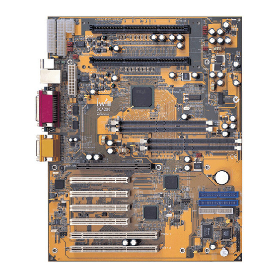
1.1 Layout ...................................................................................... 3
1.2 CPU setting .............................................................................. 4
1.3 Jumpers .................................................................................... 5
1.4 Expansion Slots / Sockets ....................................................... 7
1.5 Connectors ............................................................................... 9
1.6 Form Factor ............................................................................ 19
Chapter 2 Overview ................................ 21
Chapter 3 Features ................................. 24
3.1 Motherboard Components Placement .................................. 24
3.2 Back Panel ............................................................................. 26
3.3 Block Diagram ....................................................................... 27
3.4 Specifications ......................................................................... 28
Chapter 4 Hardware Setup .................... 31
4.1 Before Installation ................................................................. 31
4.3 Install the Processor .............................................................. 35
4.4 Install Memory Modules ...................................................... 35
4.5 Install PCI Expansion Cards ................................................. 37
4.6 Usage of the AGP Pro slot .................................................... 38
4.7 Connect Devices and Power Supply ..................................... 39
DCA200-N Series Rev 1.3A
FB2A518201300
1
Advertisement
Table of Contents

Related Manuals for IWILL dca200


Summary of Contents for IWILL dca200
-
Page 1: Table Of Contents
4.3 Install the Processor .............. 35 4.4 Install Memory Modules ............35 4.5 Install PCI Expansion Cards ..........37 4.6 Usage of the AGP Pro slot ............ 38 4.7 Connect Devices and Power Supply ........39 DCA200-N Series Rev 1.3A FB2A518201300... - Page 2 5.7 Power Management Setup ............ 70 5.8 PnP/ PCI Configurations ............74 5.9 PC Health Status ..............75 5.10 IWILL Smart Setting ............76 5.11 Load Fail-Safe Defaults ............77 5.12 Load Optimized Defaults ............. 77 5.13 Set Supervisor / User Password Setting ......78 5.14 Save &...
-
Page 3: Chapter 1 Quick Installation
Quick Installation Several easy installation steps will be described in this chapter to help the experienced users with quick installation. If you are a beginner, or need to know more about this product, please refer to Hardware Setup. Layout DCA200 Series... -
Page 4: Cpu Setting
Pentium III Xeon 667 256K-on-die SECC 667Mhz(133x5) Pentium III Xeon 667 256K-on-die 12V, SECC 600Mhz(133x5) Pentium III Xeon 733 256K-on-die 2.8V, SECC 733Mhz(133x5.5) Pentium III Xeon 733 256K-on-die SECC 733Mhz(133x5.5) Pentium III Xeon 733 256K-on-die 12V, SECC 733Mhz(133x5.5) DCA200 Series... -
Page 5: Jumpers
JP1 (CMOS) Clear CMOS jumper JP6 (PS2_SB) PS/2 power standby jumper This jumper is used to select the power well of PS/2 ports. The feature “power on by keyboard / mouse” can be enabled or disabled by this jumper. DCA200 Series... - Page 6 JP14 (S_spkr) Speaker source select jumper This jumper is used to select Speaker source jumper. JP15 (LAN) LAN Enabled / Disabled jumper (DCA200-N only) This jumper is used to enable / disable the onboard LAN chip. JP16 (FLASH) FLASH protect jumper This jumper is used to select the Flash ROM protected mode.
-
Page 7: Expansion Slots / Sockets
Chapter 1 Quick Installation Expansion Slots / Sockets J1—J2 (CPU0—CPU1) (Slot2) Processor connectors J3—J4 (RIMM_A0—RIMM_A1) 184-Pin RIMM Sockets If you install two DRDRAMs and two C-RIMM, you can refer to above figure. DCA200 Series... - Page 8 J5—J6 (RIMM_B0—RIMM_B1) 184-Pin RIMM Sockets If you install four DRDRAMs, you can refer to figure. Install memory in any combination as follows: l l i y l l J12—J15 (PCI 1—PCI 4) PCI expansion slots (32bit / 33MHz) DCA200 Series...
-
Page 9: Connectors
Chapter 1 Quick Installation J16—J17 (PCI 64_1—PCI 64_2) PCI expansion slots (64bit / 66MHz) J27 (AGP PRO) 4xAGP AGP Pro Slot Connectors J28 (IDE0) Primary ATA/66 IDE channels J29 (IDE1) Secondary ATA/66 IDE channels DCA200 Series... - Page 10 Chapter 1 Quick Installation J30 (FDC) Floppy connector J37 ATX power connector DCA200 Series...
- Page 11 Chapter 1 Quick Installation J37A (WTXA) WTX 24PIN power connector J37B (WTXB) WTX 22PIN power connector J37C (WTXC) WTX 8PIN power connector DCA200 Series...
- Page 12 Chapter 1 Quick Installation J1A & J1B Fan connectors for Dual Retention Module (4cm type Fan) J2A & J2B Fan connectors for Dual Retention Module (4cm type Fan) DCA200 Series...
- Page 13 J39A (TCPU 0) & J40A (TCPU 1) & J41A (TSYS) This motherboard has three temperature sensor headers. You can connect the tempera- ture sensor to these headers in order to monitor and CPU the temperature.These three connectors without orientation limit. DCA200 Series...
- Page 14 Chapter 1 Quick Installation J42 Chassis Intrusion Connector (CASE) The connector is for a chassis designed for chassis intrusion detection. This connector is composed of all the headers that may be connected to the front panel of the chassis. DCA200 Series...
- Page 15 J44 (SB_LINK) This is the SB_LINK connector. In order to enabling users to play real-mode DOS games. Connect the cable provided by PCI sound card to this connector. J45 (IR) This connector is designed for the SIR/FIR/CIR devices. DCA200 Series...
- Page 16 J47 (WOM) This connector can be connected to MR card or internal modem card to provide the ability of power on by modem device. J48 (SMBUS) This connector provides the connectivity of SMBUS utilization. DCA200 Series...
- Page 17 Chapter 1 Quick Installation DCA200 Series...
- Page 18 These connectors allow you to receive stereo audio input from such sound sources as a CD-COM, TV tuner or MPEG card. External COM1 connector External COM2 connector External Parallel connector External PS/2 mouse & keyboard connector External Dual USB & RJ45 connector External Game / Line-in / Line-out / MIC connector DCA200 Series...
-
Page 19: Form Factor
Chapter 1 Quick Installation Form Factor DCA200 Series... - Page 20 Chapter 1 Quick Installation DCA200 Series...
-
Page 21: Chapter 2 Overview
Chapter 2 Overview Thank you for purchasing the IWILL DCA200-N motherboard. This operation manual will instruct you how to configure and install the system properly. It contains an overview about the engineering design and features of this product. Also, this manual provides useful information for later upgrades or configuration changes. - Page 22 Xeon™ processors (Itanium™) without any headache. This motherboard can support the processors that packed as a SECC type. In other words, no matter what kind of processors you have in SECC , the DCA200 motherboard always provides you an adequate solution.
- Page 23 Chapter 2 Overview further testing or modification. Iwill Corporation assumes no responsibility for any errors that may appear in this document. YEAR 2000 issue All motherboard currently shipped from IWILL contain BIOS capable of handling the year 2000 data correctly.
-
Page 24: Chapter 3 Features
Chapter 3 Features Chapter 3 Features This Iwill DCA200 / DCA200-N motherboard are well designed for the user. Who wants the most stable plat form, best performance/price ratio and convenience. Motherboard Components Placement DCA200-N Series... - Page 25 11. Intel P64H Chipset. 12.64 bit/66 MHz Bus Master PCI Slot. 13.AC’97 V2.1 Audio CODEC. 14.32 bit/33 MHz Bus Master PCI Slot. 15.Intel 82559 Lan Chip 10/100M BaseT (DCA200-N only). 16.AGP Pro Slot. 17.Joystick, Midi Line out,Line in, Microphone In Connector. 18.COM2 Connector.
-
Page 26: Back Panel
Chapter 3 Features Back Panel DCA200-N Series... -
Page 27: Block Diagram
Chapter 3 Features Block Diagram DCA200-N Series... -
Page 28: Specifications
Provides one floppy port to support 1.2M/1.4M/2.8M/3 Mode FDD and QIC-80 tape drive Supports two high-speed 16550A serial ports Supports one ECP/EPP parallel port Supports one PS2 mouse port Supports one PS2 keyboard port Provides one Game/MIDI port to support two joysticks DCA200-N Series... - Page 29 Supports four 32bit/33MHz Bus Master PCI slots Supports two 64bit/66MHz Bus Master PCI slots Supports one 4xAGP AGP Pro slot for AGP cards LAN on board (DCA200-N only) Build-in Intel i82559 Ethernet LAN controller (10Base-T/100Base-TX) Supports IEEE 802.3u Auto-Negotiation Supports WfM (Wired for Management) Supports Alert-on-LAN Supports Full-Duplex Flow Control (IEEE 802.3x)
- Page 30 Chapter 3 Features O t h e r s WTX Form Factor 36“ x 29” DCA200-N Series...
-
Page 31: Chapter 4 Hardware Setup
1-2, place onto pins 2-3, and then place back onto pins 1- 2 again. Then, turn on your computer, press <Del> key during boot up and enter the BIOS setup program to re-set your preferences. DCA200-N Series... - Page 32 Pentium III Xeon 667 256K-on-die SECC 667Mhz(133x5) Pentium III Xeon 667 256K-on-die 12V, SECC 600Mhz(133x5) Pentium III Xeon 733 256K-on-die 2.8V, SECC 733Mhz(133x5.5) Pentium III Xeon 733 256K-on-die SECC 733Mhz(133x5.5) Pentium III Xeon 733 256K-on-die 12V, SECC 733Mhz(133x5.5) DCA200-N Series...
- Page 33 PS/2 ports. 4.2.3 JP14 Speaker source select jumper (S_spkr) This jumper is used to enable / disable the onboard audio CODEC. The onboard audio CODEC must be disabled when using an ISA/PCI audio card or a primary AMR card. DCA200-N Series...
- Page 34 Chapter 4 Hardware Setup 4.2.4 JP15 LAN Enabled / Disabled jumper (LAN) (DCA200-N only) This jumper is used to enable / disable the onboard LAN chip. 4.2.5 JP16 Flash protect jumper (FLASH) This jumper is used to select the Flash ROM protected mode.
-
Page 35: Install The Processor
MHz to 800 MHz transfer rates while using conventional system and board design technologies. The chipset supports ECC memory module (Single bit error Correction, Multiple bit error Detection) and increases storage, bandwidth. The motherboard also support SPD (Serial Presence Detect) architecture to provide the best choice for performance vs. stability. DCA200-N Series... - Page 36 Chapter 4 Hardware Setup l l a l l a l l i y l l l l a DCA200-N Series...
-
Page 37: Install Pci Expansion Cards
You can expand the features of the computer by adding some expansion cards. You can select the latest IWILL SCSI controller, such as DU280 and DU3160. Before you do that, read the documentation for your expansion card carefully and make any necessary hardware settings on it, such as jumpers or switches. -
Page 38: Usage Of The Agp Pro Slot
AGP interface specification. It includes an enhanced connector, improve cooling system, from factor specifications such as graphics users on both IA-32 and IA- 64 platforms. The new specification will be supported in both AGP 2x and AGP 4x modes. DCA200-N Series... -
Page 39: Connect Devices And Power Supply
A legacy ATA (IDE) drive can coexist with an Ultra ATA/66 drive. However, for the Ultra ATA/66 device to attain Ultra DMA 4 mode, an Ultra ATA/66 capable cable is required. Orient the red markings on the ribbon cable to pin1 of the connector DCA200-N Series... - Page 40 44M, 2.88M, 3 Mode floppy drives and QIC-80 floppy tape drive. After connecting the single end to the board, connect the two plugs on the other end to the floppy devices. Orient the red markings on the ribbon cable to pin1 of the connector 4.7.3 Back Panel DCA200-N Series...
- Page 41 Ethernet RJ45 Connector The RJ45 connector is optional at the time of purchase and is located on top of the USB connectors. The connector allow the motherboard to connect to a Local Area Network (LAN) through a network hub. DCA200-N Series...
- Page 42 You may use the hardware monitoring utility to monitor the Rotations per Minute (RPM) of the fan. 1. The CPU will overheat if there is no airflow across the CPU heatsink. 2. Damage may occur to the CPU fan and/or motherboard if these pins are incorrectly used. DCA200-N Series...
- Page 43 Chapter 4 Hardware Setup 4.7.4.1 J1A & J1B Fan connectors for Dual Retention Module (4cm type Fan) 4.7.4.2 J2A & J2B Fan connectors for Dual Retention Module (4cm type Fan) DCA200-N Series...
- Page 44 When any chassis component is removed, the contact should open and the motherboard will record a chassis intrusion event. If this feature is not used, a jumper cap must be placed over the 2 pins of the connector. DCA200-N Series...
- Page 45 This 2-pins connector is for a ACPI power status indicator. The LED status will depend on the connector. 4.7.7.3 IDE LED Connector (ALED) This 2-pin connector connects to the case-mounted IDE LED, which lights when the IDE devices connected to the primary / secondary IDE connectors are working. DCA200-N Series...
- Page 46 This 4-pin connector connects to the case-mounted speaker. 4.7.8 Creative SB_LINK Header This is the SB_LINK connector. In order to enabling users to play real-mode DOS games. Connect the cable provided by PCI sound card to this connector. DCA200-N Series...
- Page 47 When using a SIR/FIR devices, you need to enter the BIOS setup program and configure the “ART Mode Select” field as “IrDA”. b. When using a CIR device, the jumper cap of JP6 should be placed over 1-2 in order to use Consumer Infrared power up. DCA200-N Series...
- Page 48 For the external Modems, the Wake-On-Modem is detected through the COM port. b. You need to enable the “Wake Up by Ring/LAN” feature in the BIO setup program. c. Your system must have a ATX power supply with at least 720mA 5VSB power. DCA200-N Series...
- Page 49 4.7.12 SMBUS connector J48 (SMBUS) This connector provides the connectivity of SMBUS utilization. 4.7.13 Internal Audio Connector (AUX_IN) & (CD_IN) These connectors allow you to receive stereo audio input from such sound sources as a CD-ROM, TV tuner or MPEG card. DCA200-N Series...
- Page 50 In order to support the power up function other than power/soft-off button, such as Wake-On-LAN, Wake-On-Modem, your ATX power supply must supply at least 720mA 5VSB. We would like to suggest you to use over 300 power supply. 4.7.15 WTX Power Supply Connector DCA200-N Series...
- Page 51 4.7.16.3 Connect the power cord into the power supply located on the back of your system case (please refer to the manual of your power supply). 4.7.16.4 Connect the power cord into a power outlet that is equipped with a surge protector. DCA200-N Series...
- Page 52 4.7.18.2 Shut down your operating system. 4.7.18.3 Switch off the power button. If you are using Windows 95/98, the power supply should turn off automatically after Windows shut down. 4.7.18.4 Turn off all the external devices. 4.7.18.5 Turn off your monitor. DCA200-N Series...
-
Page 53: Chapter 5 Bios Setup
The BIOS can be upgraded from a diskette with the Award Flash utility — AWDFLASH.EXE. The BIOS image file, and update utility are available from IWILL’s WEB site: www.iwill.net 5.1.2 Enter BIOS setup program Power-on the system by either pressing the Power-On button, or by using any of the power-on features provided by the motherboard. -
Page 54: Main Menu
The main menu allows you to select from several setup pages. Use the arrow keys to select among these pages and press <Enter> key to enter the sub-menu. A brief description of each highlighted selection appears at the bottom of the screen. 5.3 Standard CMOS Features DCA200-N Series... - Page 55 BIOS automatically fills in the values for the cylinders, heads and sectors fields N o n e No disk drives are attached 5.3.3.3 Capacity Your disk drive size 5.3.3.4 Access Mode This field specifies the IDE translation mode. DCA200-N Series...
- Page 56 Drive B A 3 Mode drive is connected as drive B Both Both drive A and drive B are 3 Mode drives 5.3.6 Video This field specifies the type of the graphics adapters used by the primary system monitor. DCA200-N Series...
-
Page 57: Base Memory
5.3.9 Extended Memory This is the amount of memory located above 1MB in the processor’s memory address map. This field has no options. 5.3.10 Total Memory Displays the total memory available in the system 5.4 Advanced BIOS Features DCA200-N Series... -
Page 58: Virus Warning
If you run such a program, we recommend that you first disable the Virus Warning function beforehand. Options Enabled Disabled (*) 5.4.2 CPU Internal Cache This field configures the CPU internal cache (L1 cache). Options Enabled (*) Disabled 5.4.3 External Cache DCA200-N Series... -
Page 59: Cpu L2 Cache Ecc Checking
The BIOS attempts to load the operating system from the devices in the sequence selected in these items. Options Floppy (*) LS/ZIP HDD-0 (**) SCSI (***) CD-ROM HDD-1 HDD-2 HDD-3 Disable 5.4.8 Swap Floppy Drive When enabled, floppy drives A and B will be exchanged without the user physically DCA200-N Series... -
Page 60: Boot Up Floppy Seek
Options 6 (*), 8, 10, 12, 15, 20, 24, 30 5.4.14 Typematic Delay (Msec) When enabled, typematic delay allows you to select the time delay between when the key is first pressed and when the acceleration begins. DCA200-N Series... -
Page 61: Security Option
When enabled, the extended ROM data located at the respective address range will be copied to system memory. Options Enabled / Disabled (*) Advanced Chipset Features This setup page is used to specify advanced features available through the chipset. The DCA200-N Series... -
Page 62: System Bios Cacheable
When ECC is selected, all memory modules used by the system must support ECC. Options Non-ECC (*) 5.5.3 System BIOS Cacheable When enabled, accesses to the system BIOS will be cached. Options Enabled (*) Disabled 5.5.4 Video BIOS Cacheable DCA200-N Series... -
Page 63: Video Ram Cacheable
5.5.8 AGP Aperture Size (MB) This field specifies the size of system memory that can be used for AGP graphics aperture. Options 4 / 8 / 16 / 32 / 64 (*) / 128 / 256 Integrated Peripherals DCA200-N Series... - Page 64 Higher setting may exceed the capability of older IDE device and cause problem. PIO Mode Setting Maximum transfer rate PIO Mode 0 3.3 MB/sec PIO Mode 1 5.2 MB/sec PIO Mode 2 8.3 MB/sec PIO Mode 3 11 MB/sec PIO Mode 4 16.6 MB/sec Options Description DCA200-N Series...
-
Page 65: Usb Controller
Select Enabled if you want to use USB keyboard under DOS Options Enabled Disabled (*) 5.6.6 Init Display First This item allows you to decide which slot to activate first, either PCI slot or AGP slot. Options PCI Slot AGP (*) 5.6.7 AC97 Audio/Modem DCA200-N Series... -
Page 66: Ide Hdd Block Mode
KB Power On Password In you wish to use this function, bring the cursor to the field written “Enter”, then press <Enter>. The computer will display the message, “Enter Password”. Type your password and press <Enter>. After the message DCA200-N Series... -
Page 67: Onboard Fdc Controller
5.6.12 COM2 Mode Select This field must be configured in order to use the infrared connector, which supports infrared wireless transmitting and receiving of data between devices when using the appropriate application software. Options Normal (*), IrDA, ASKIR DCA200-N Series... -
Page 68: Onboard Parallel Port
5.6.14.1 EPP Mode Select When the Parallel Port Mode field is configured as EPP, ECP+EPP mode, the EPP version needs to be specified. Please refer to your peripheral document before selecting field. Options Description EPP1.7 Use EPP 1.7 protocol DCA200-N Series... -
Page 69: Midi Port Address
Disabled (*) Disables midi port Port address 330h Port address 300h Port address 290h 5.6.18 Midi Port IRQ This field configures the midi port IRQ. There are several IRQs to select from. Options Description 5 (*) Port address IRQ5 DCA200-N Series... -
Page 70: Power Management Setup
This is the Suspend-To-Ram state, all system data will be saved in system’s memory and all devices except the memory will shut off. 5.7.2 Power Management This feature allows the user to select the default parameters for the power-saving mode. Options Description DCA200-N Series... -
Page 71: Video Off Method
This field specifies the time the system enters HDD power down. It is available only when the Power Management field is set to User Define. Options 1 Min / 2 Min / 3 Min / 4 Min / 5 Min / 6 Min DCA200-N Series... - Page 72 Disabled (*) 5.7.12 CPU Thermal throttling This field specifies the throttling function of CPU Thermal. When the CPU’s temperature attain it’s default protection point, the CPU will run slower in order to descend the heat generation from itself. DCA200-N Series...
- Page 73 If enabled, timer restarts whenever the master disk of the secondary IDE channel is active. Options Enabled Disabled (*) 5.7.14.4 Secondary IDE 1 If enabled, timer restarts whenever the slave disk of the secondary IDE channel is active. Options Enabled Disabled (*) DCA200-N Series...
-
Page 74: Pnp/ Pci Configurations
Options Enabled Disabled (*) 5.8.3 Resources Controlled By The Award Plug and Play BIOS has the capacity to automatically configure all of the boot and Plug and Play compatible devices. However, this capability DCA200-N Series... -
Page 75: Pc Health Status
PCI VGA co-works with ISA MPEG card Disabled (*) All cases except above PC Health Status This page is monitoring your status of computer. On the screen displays CPU/System temperature, FAN speed, and voltages. 5.10 IWILL Smart Setting DCA200-N Series... - Page 76 5.10.1 CPU CLOCK ADJUST Mode When choosing Plug & Run , the CPU frequency will be detected automatically. This function will only support DCA200 series, and provides to survey automatically CPU FSB. Let the O.S may run the stablest condition.
-
Page 77: Load Fail-Safe Defaults
When you press <Enter> on this item you get a confirmation dialog box with a message similar Pressing ‘Y’ loads the default values that are factory settings for optimal performance system operations. 5.13 Set Supervisor / User Password Setting DCA200-N Series... -
Page 78: Set Supervisor / User Password Setting
Please keep your password in safe place. 5.14 Save & Exit Setup Saves current CMOS value and exit BIOS setup program. 5.15 Exit Without Saving Abandons all CMOS value changes and exits BIOS setup program. DCA200-N Series... -
Page 79: Chapter 6 Power Installer Cd
Power Installer CD Software Installation The attached Power Installer CD contains all the necessary drivers, utilities for IWILL’s full range of motherboards. It provides an easy way for users to install the needed drivers without going through a complicated process. The Power Installer CD is able to auto-detect and display the drivers, utilities needed for your motherboard. - Page 80 This bootable Power Installer CD also allows you to boot up your system, even when the OS has not been installed. During the boot-up process, you can perform “IWILL Diskette Creator,” which will automatically make the driver diskettes you need.
-
Page 81: Installing Operating Systems
6.2.12 How to use Suspend to Disk Guide Simply click on the Suspend to Disk Guide shown on screen, then follow the prompts to complete setup. Installing Operating Systems This section briefly demonstrates how to install a few popular software operating DCA200-N Series... - Page 82 Setup will initialize. Then, Windows 98 Setup begins. Please follow the instructions that are displayed. Setup may ask you to insert your original Windows 95 or Windows 3.1 disks if you’re using the upgrade version of Windows 98. DCA200-N Series...
- Page 83 Select “Boot Sequence” and change the default setting from A, C, SCSI to “CD-ROM, C, A” using Page Up /Page Down key, save, and reboot. Place the Windows NT 4.0 CD-ROM in the drive, and boot from CD-ROM. Follow all instructions to finish Windows NT installation. DCA200-N Series...
Need help?
Do you have a question about the dca200 and is the answer not in the manual?
Questions and answers