Table of Contents
Advertisement
Quick Links
Advertisement
Table of Contents

Related Manuals for IWILL DH800


Summary of Contents for IWILL DH800
- Page 2 INDEX FCC Guidelines Information to User Disclaimer of Warranties Copyright Trademark Recognition Static Electricity Precautions Package Contents Before Using the Motherboard... Handling the Motherboard Tips in Handling the Motherboard Quick Installation Guide Chapter 1 Components and Features 1.1 Motherboard Layout 1.1.1 Components 1.2 Chipset 1.3 CPU Socket...
- Page 3 1.6 Rear Panel I/O Ports 1.6.1 PS/2 Keyboard and PS/2 Mouse Ports 1.6.2 Parallel Port 1.6.3 Serial Port 1.6.4 Rear Out and Center Out Jacks 1.6.5 S/PDIF Out Jack 1.6.6 LAN Port 1.6.7 USB Port 1.6.8 Audio Jacks 1.7 SATA Connectors 1.8 IDE Drive Connectors 1.9 Floppy Disk Drive Connectors 1.10 SMBus Connector...
- Page 4 Chapter 2 Hardware Installation 2.1 Jumper Settings 2.1.1 Clear CMOS -JP1 2.1.2 BIOS Flash Protect - JP16 2.2 Motherboard Installation 2.2.1 Installing the Xeon CPU @ 533MHz FSB 2.2.2 Installing the Xeon CPU @ 800MHz FSB 2.3 Memory Installation Chapter 3 BIOS Overview STARTING THE BIOS SETUP...
- Page 5 FCC Guidelines This equipment has been tested and found to comply with the limits for a Class B digital device, pursuant to Part 15 of the FCC rules. These limits are designed to provide reasonable protection against harmful interference in a residential installation. This equipment generates, uses and can radiate radio frequency energy and, if not installed and used in accordance with the instructions may cause harmful interference to radio communications.
- Page 6 Information to User: Any changes or modifications not expressly approved by the party responsible for compliance could void the user's authority to operate this equipment. Shielded interference cable, if any, must be used in order to comply with emission limits. Disclaimer of Warranties The information in this document is subject to change without notice.
- Page 7 Static Electricity Precautions It is quite easy to inadvertently damage your PC, mainboard, components or devices even before installing them in your system unit. Static electrical discharge can damage computer components without causing any signs of physical damage. You must take extra care in handling them to ensure against electrostatic build-up.
- Page 8 Package Contents The motherboard package includes the following items: DH800 motherboard ATA-66/100 IDE cable Serial ATA cable + SATA power cable Floppy disk drive cable Rear panel I/O shield Two heat sink retention modules 3 jumper caps (Extra caps in case original caps get lost.)
- Page 9 Before Using the Motherboard... Before you install and use the motherboard, please check the following: Package contents Make sure the package contains all items listed above. If any of these items are missing, please contact your dealer or sales representative for assistance. Damaged accessories If any of the items are damaged, please contact your dealer or sales representative for assistance.
- Page 10 Handling the Motherboard It is quite easy to inadvertently damage the motherboard even before installing it in your system unit. Electrostatic discharge can damage computer components without causing any signs of physical damage. You must take extra care in handling the motherboard to ensure that no static build-up is present.
- Page 11 Quick Installation Guide Step 1 Install the CPU, CPU fan / heatsink and other system fans. Step 2 Install the DIMM. Step 3 Install add-in cards. Step 4 Configure the jumpers. Step 5 Connect the floppy disk drive cable and IDE disk drive cable to their respective devices.
-
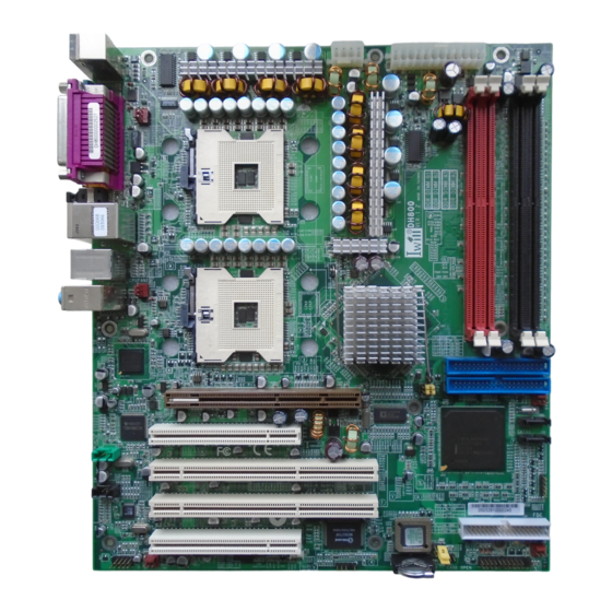
Page 13: Motherboard Layout
1.1 Motherboard Layout Mounting Hole EPS 12V Power Connector CPU FAN1 DIMM Slots FAN2 AUX_IN SATA JP3A & JP3 CD_IN SMBUS SYSFAN 2 JP16 SYSFAN 1 1394 Connector Front Panel Case Open... - Page 14 1.1.1 Components Description Location CPU Sockets CPU1 , CPU2 Channel A DIMM slots A1 (J5) , A2 (J6) Channel B DIMM slots B1 (J3) , B2 (J4) PCI 1 , PCI 2 J12 , J13 PCI-X 1, PCI-X 2 J14 , J15 EPS 12V (24 pin) EPS 12V (8 pin) J37A...
- Page 15 1.2 Chipset Intel Chipset North bridge: Intel 875P Memory Controller Hub South bridge: Hance Rapid I/O Controller Hub Intel LAN Controller Intel 82547GI Gigabit Ethernet Controller T.I. IEEE-1394 Controller T.I. TSB43AB22A Controller Support 1394a specification Analog Devices Audio Controller Analog Devices AD1980 Controller Support 6-channel audio function Super I/O Controller Winbond W83627THF...
-
Page 16: Cpu Socket
Refer to Chapter 2 for information on the CPU installation procedure BIOS Settings The BIOS automatically detects the CPU clock. You can manually configure the settings in the IWILL Smart Setting submenu of the BIOS. Refer to chapter 3 for more information. -
Page 17: System Memory
1.4 System Memory Function The DIMM sockets are for installing DDR SDRAM memory modules. The sockets function independently allowing a variety of configurations: Four DDR DIMM sockets Support dual channel memory interface Each channel supports 2 DIMM sockets PC1600 (DDR200) / PC2100 (DDR266) / PC2700 (DDR333) / PC3200 (DDR400) DDR SDRAM modules Support Unbuffered ECC / Non-ECC memory modules Support maximum of 4GB memory using 64, 128, 256, 512 MB or 1GB... -
Page 18: Expansion Slots
1.5 Expansion Slots 1.5.1 AGP slot Function The AGP slot is for installing an AGP interface video display card. It is AGP 3.0 compliant. The slot supports three types of AGP cards: AGP 8x (2.13GB/sec bandwidth) AGP 4x (1066MB/sec. bandwidth) AGP Pro 50 (The slot is extended to support AGP Pro cards that use up to 50 watts of power) AGP 8X / Pro J11... -
Page 19: Pci Slots
1.5.2 PCI slots Function This motherboard has four Bus Master capable PCI expansion slots, including two 32-bit 33MHz slots and two 64-bit PCI-X slots operating at 66MHz. BIOS Settings The BIOS automatically configures Plug and Play and other PCI bus settings. - Page 20 1.6 Rear Panel I/O Ports 1.6.1 PS/2 Keyboard and PS/2 Mouse Ports Mouse Keyboard Function The PS/2 mouse (Green) and PS/2 keyboard (Purple) ports are for connecting a PS/2 mouse and PS/2 keyboard respectively. The PS/2 mouse port uses IRQ12. If a mouse is not connected to this port, the system will reserve IRQ12 for other expansion cards.
-
Page 21: Parallel Port
1.6.2 Parallel Port Function The standard parallel port (Burgundy) is for interfacing your PC to a parallel printer. It supports SPP, ECP and EPP modes. SPP (Standard Parallel Port) Allows normal speed operation but in one direction only. ECP (Extended Capabilities Port) Allows parallel port to operate in bidirectional mode and at a speed faster than the SPP's data transfer rate. -
Page 22: Serial Port
1.6.3 Serial Port COM1 Function The serial ports are RS-232C asynchronous communication ports with 16C550A-compatible UARTs that can be used with modems, serial printers, remote display terminals, and other serial devices. It can operate at speeds up to 115,200bps. You can configure the port's speed in the computer's Operating System. - Page 23 1.6.4 Rear Out and Center Out Jacks Rear Out Center Out Function The rear out (black) and center out (orange) jacks support four audio output signals. The rear out jack supports rear right channel and rear left channel. The center out jack supports center channel and subwoofer.
-
Page 24: S/Pdif-Out Jack
1.6.5 S/PDIF Out Jack S/PDIF-Out Function S/PDIF is a standard audio file transfer format that transfers digital audio signals to a device without having to be converted first to an analog format. This prevents the quality of the audio signal from degrading whenever it is converted to analog. - Page 25 1.6.6 LAN Port Function The LAN port uses a CAT 5 LAN cable for connecting the motherboard to a local area network by means of a network hub. The port has 2 indicator LEDs. Speed LED (left) • 10Mbps - will not blink •...
- Page 26 1.6.7 USB Port USB1 USB3 USB2 USB4 Function The motherboard supports USB 2.0 and USB 1.1 ports. USB 1.1 supports 12Mb/second bandwidth while USB 2.0 supports 480Mb/second bandwidth providing a marked improvement in device transfer speeds between your computer and a wide range of simultaneously accessible external Plug and Play peripherals.
-
Page 27: Audio Jacks
1.6.8 Audio Jacks Function • Line-in Jack (Light Blue) This jack is an audio input connector for an external audio source. • Line-out Jack (Lime) This jack is used to connect stereo speakers for audio output. • Mic-in Jack (Pink) This jack is used to connect an external microphone. -
Page 28: Sata Connectors
1.7 SATA Connectors Serial ATA is a storage interface that is compliant with SATA 1.0 specification. With speed of up to 1.5Gbps, it improves hard drive performance even in data intensive environments such as audio/video, consumer electronics and entry-level servers. The Hance Rapid chip supports RAID level 0, 1 on devices connected to the two SATA ports. -
Page 29: Ide Drive Connectors
1.8 IDE Drive Connectors Function The 2 IDE disk drive connectors are Primary and Secondary IDE channels for connecting up to four ATA/100 IDE devices. It supports PIO (Programmable Input/Output) and DMA (Direct Memory Access) mode operations for a maximum data transfer rate of 100Mbps per channel. - Page 30 Connecting IDE Drives Install one end of the IDE cable into the IDE 1 header on the motherboard and the other connectors to the IDE devices. If you are adding a third or fourth IDE device, use another IDE cable and install one end of the cable into the IDE 2 header on the motherboard and the other connectors to the IDE devices.
-
Page 31: Smbus Connector
1.9 Floppy Disk Drive Connectors Function The FDD connector is for connecting up to two floppy disk drives. Connecting Floppy Drives Install one end of the floppy disk drive cable into the floppy disk header on the motherboard and the other end-most connector to the drive you want to designate as Drive A. -
Page 32: Front Panel Connector
1.11 Front Panel Connector Function The front panel connector (J44) on the motherboard supports several system indicators and controls that connect to the front panel of the system chassis. This will enable you to determine information about the system’s operational status and provide some system controls. These include the: Reset Switch This switch connects to the system's Reset button allowing you to... - Page 33 • Power On Switch This switch connects to the system's Power button allowing you to power on and off the system. You can configure the system to use the keyboard or mouse to power-on the system. You can also configure the system to respond to power restoration after a power outage occurs.
-
Page 34: Eps12V Power Connector
1.12 EPS12V Power Connector Connecting a 450-Watt EPS 12V Power Supply The motherboard requires using a 450-Watt EPS 12V power supply. Leads from the power supply will plug into the two power connectors (J1 and J3) on the motherboard. The 24-pin (J1) and 8-pin (J3) power connectors are not standard ATX connectors. -
Page 36: Jumper Settings
2.1 Jumper Settings 2.1.1 Clear CMOS - JP1 Function The BIOS CMOS Setup Utility creates system configuration record that is stored in CMOS memory in the real-time clock chip. If the CMOS data becomes corrupted, you can use this jumper to delete the data stored in the CMOS memory and reset the configuration to the CMOS Setup Utility's Optimized Defaults. - Page 37 Flash memory. Settings 1-2 On Protection mode selected in the " Iwill Smart Setting " submenu of the BIOS. (default) 2-3 On BIOS Write Protection Enabled All Off BIOS Write Protection Disabled...
-
Page 38: Motherboard Installation
2.2 Motherboard Installation This section explains the basic requirements for installing the motherboard in a system housing or " chassis ". Since housing designs vary widely, you will need to consult the housing documentation for specific information. To install the motherboard in a system housing, you will need to do the following: Install a rear panel I/O shield Attach the board to the housing... - Page 39 CPU & HeatSink Installation IWILL DH800 supports two different specification of processor; therefore please follow direction as below according to the processor you bought.
- Page 40 2.2.1 Installing the Xeon CPU @ 533MHz FSB Step 1 Position the attached screws for the special-designed iron plate.
- Page 41 Step 2 Screw this plate to the chassis you will use to install this motherboard. Please position the case mounting hole of this plate to the chassis. Do not install here!
- Page 42 Step 3 Position IWILL DH800 on top of this plate and screw the motherboard to the chassis. Step 4 Position processor on the CPU socket.
- Page 43 Step 5 Screw Retention Module on top of this motherboard Step 6 Put CPU HeatSink on the top of the CPU, apply the clip to adjust the heatsink to be steady and finish the installation...
- Page 44 2.2.2 Installing the Xeon CPU @ 800MHz FSB Step 1 Put the attached Hat Spring to the back of this motherboard...
- Page 45 Step 2 Repeat step 1 ~ step 4 in 2.2.1 Step 3 Position the CPU HeatSink on the top of the CPU; screw it to the motherboard and finish the installation...
-
Page 46: Memory Installation
2.3 Memory Installation The DDR module is held in the socket by the retaining arms on each side. The module's edge connector are of different widths and there are key notches in each module. These ensure that you won't insert the module incorrectly. - Page 47 2. Hold the module perpendicular to the motherboard and press the edge connector into the socket. 3. Press the module completely into the socket so that the retaining arms will engage the retention notches at each end of the module.
- Page 49 Overview This chapter discusses the AMIBIOS Setup program built into the ROM BIOS. The Setup program allows users to modify the basic system configuration. The BIOS is the Basic Input / Output System used in all IBM PC, XT, AT, and PS/2 compatible computers.
-
Page 50: Starting The Bios Setup
STARTING THE BIOS SETUP The AMIBIOS is immediately activated every time you power on the system. The BIOS reads the system information contained in the CMOS and begins the process of checking the system and configuring it. After configuring the system, the BIOS will follow the Boot Order to seek out an operating system. -
Page 51: Using The Bios Setup Utility
USING THE BIOS SETUP UTILITY Navigating through the BIOS Setup Utility is straight forward. Use the arrow keys to highlight items, press <Enter> to select items in menus, and press <Esc> to quit. The following table provides more details about how to navigate in the Setup program using the keyboard. Up ArrowKey Move to the previous item Down Arrow Key... - Page 52 IMPORTANT The BIOS does NOT automatically save values that you have modified. If you do not save your values before you exit the BIOS Setup Utility, all your changes will be lost. If after making and saving system changes with the BIOS Setup Utility, you discover that your computer is no longer able to boot, the AMIBIOS supports an override, which will reset your system to the Failsafe defaults.
- Page 53 3.1 Main Menu This is the first screen that is displayed when you enter the BIOS Setup Utility. Each tab lined on the top of the screen represents each different menu. The following picture shows the main menu. Main menu shows the information of BIOS version, date and ID;...
-
Page 54: Advanced Pci/Pnp Settings
3.2 Advanced PCI / PnP Settings... - Page 55 Feature Option Description Plug & Play O/S Yes: lets the O/S configure PnP devices not required for boot if your system has a Plug and Play O/S PCI Latency 32, 64, 96, 128, Value in units of PCI Timer 160,192, 224, 248 clocks for PCI device latency timer register PCI Delayed...
- Page 56 Feature Option Description IRQ3~IRQ15 Available Available: specified Reserved IRQ is available to be used by PCI/PnP devices Reserve: specified IRQ is reserved for use by legacy ISA devices DMA Channel Available Available: specified DMA is 0, 1, 3, 5, 6, 7 Reserved available to be used by PCI/PnP devices...
- Page 57 3.3 Boot Menu Feature Description Boot Device Priority Specify the boot device priority sequence Hard Disk Drives Specify the boot device priority sequence from available hard drives Removable Drives Specify the boot device priority sequence from available removable drives CD / DVD Drives Specify the boot device priority sequence from available CD / DVD drives...
-
Page 58: Specification
3.4 Specification Processor: •Dual/single Intel Xeon (socket 604) processors •Intel Xeon processors at 533MHz System Bus •2nd set VRD to support next generation Intel Xeon processors •Support 2MB L3 cache Intel Xeon processors Chipset: •Intel i875P MCH •Intel Hance Rapids ICH •Winbond W83627THF Super I/O System Memory: •Support DDR400/333/266 memory modules... - Page 59 Ethernet: •Intel Kenai II CSA for GbE LAN •1x RJ-45 •One 3-pin Wake on LAN connector •Enable/Disable by option in the BIOS Audio: •6 Channel AC'97 CODEC •Analog Device AD1980 •One audio connector at rear panel to support LINE IN/LINE OUT/MIC •Support MIC IN/LINE OUT for front panel •Rear-out, Center-out and S/PDIF-out •One 4-pin CD-ROM Audio In header...
- Page 60 •Stacked Parallel ports on one Serial, real out/center out/SPDIF out •Stacked audio Line-in, Line-out and Microphone Power Supply: •EPS12V and ATX12V Package Contents •DH800 motherboard •ATA-66/100 IDE cable •Serial ATA cable + SATA power cable •Floppy disk drive cable •Rear panel I/O shield •Two heat sink retention modules...
- Page 61 MEMO...
- Page 62 MEMO...
- Page 63 MEMO...
- Page 64 MEMO...
Need help?
Do you have a question about the DH800 and is the answer not in the manual?
Questions and answers