Table of Contents
Advertisement
Quick Links
Advertisement
Table of Contents

Related Manuals for IWILL Motherboard DJ800


Summary of Contents for IWILL Motherboard DJ800
- Page 1 I W I L L DJ800 M o t h e r b o a r d U s e r ’ s M a n u a l FB25634000...
- Page 2 U s e r ’ s M a n u a l D J 8 0 0 M o t h e r b o a r d...
- Page 3 Disclaimer The manufacturer makes no representations or warranties regarding the contents of this manual and specifically disclaims any implied warranties of merchantability or fitness for any particular purpose. Furthermore, the manufacturer reserves the right to revise this publication or make changes in the specifications of the product described within it at any time without notice and without obligation to notify any person of such revision or change.
-
Page 4: Table Of Contents
U s e r ’ s M a n u a l D J 8 0 0 M o t h e r b o a r d Overview ... 1-1 Packing list ... 1-1 Safety Notice ... 1-2 DJ800 Specification ... 1-5 Components and Jumper Setting ...2-1 Mainboard Map ... - Page 5 BIOS Setup ... 4-1 Starting the BIOS Setup ... 4-1 Using the BIOS Setup Utility ... 4-3 Main Menu ... 4-5 Advanced Menu ... 4-6 Boot Menu ... 4-7 Boot Setting Configuration Submenu ... 4-8 Exit Menu ... 4-10 OS and Drivers Installation ... 5-1 OS Installation ...
-
Page 6: Overview
Chapter Overview... - Page 7 Chapter 1 Package DJ800 Motherboard Three jumper caps (Extra caps in case original caps get lost) One Power Installation CD (contains drivers and utilities) DJ800 User’s manual Rear panel I/O shield Two sets of SATA cables One ATA-66/100 IDE cable One floppy disk drive cable Two Hat Springs for CPU cooler...
-
Page 8: General Safety Precautions
O v e r v i e w O v e r v i e w D J 8 0 0 M o t h e r b o a r d YOU MUST HAVE ENOUGH SYSTEM INTEGRATION KNOWLEDGE BEFORE THE INSTALLATION General Safety Precautions Keep the area around the Server clean and free of clutter. -
Page 9: Operating Precautions
Use a grounded wrist strap designed to prevent static discharge. Keep all components and printed circuit boards (PCBs) in their antistatic bags until ready for use. Touch a grounded metal object before removing the board from the antistatic bag. Do not let components or PCBs come into contact with your clothing, which may retain a charge even if you are wearing a wrist strap. -
Page 10: Getting Help
O v e r v i e w O v e r v i e w D J 8 0 0 M o t h e r b o a r d Getting Help If a problem arises with your system during Installation or Operation, you should first ask your dealer for help as they have most likely config- ured your system. -
Page 11: Dj800 Specification
DJ800 Specifications ® Intel Dual Xeon Socket 604 CPUs Processor Supports 800MHz FSB Intel E7525 Chipset MCH Intel ICH5R Chipset Intel PXH Winbond 83627 HF 8 DIMMs for 240-pin DDR2 400 DIMM sockets Uses Registered DDR2 with ECC or Non-ECC memory Memory Supports total system memory size of up to 16GB Intel 82541PI Gigabit Ethernet Controller... - Page 12 O v e r v i e w O v e r v i e w D J 8 0 0 M o t h e r b o a r d Internal I/O connector IDE Bus Rear Panel I/O System BIOS System Management Form Factor...
-
Page 13: Components And Jumper Setting
Chapter 2 Components and Jumper Setting... -
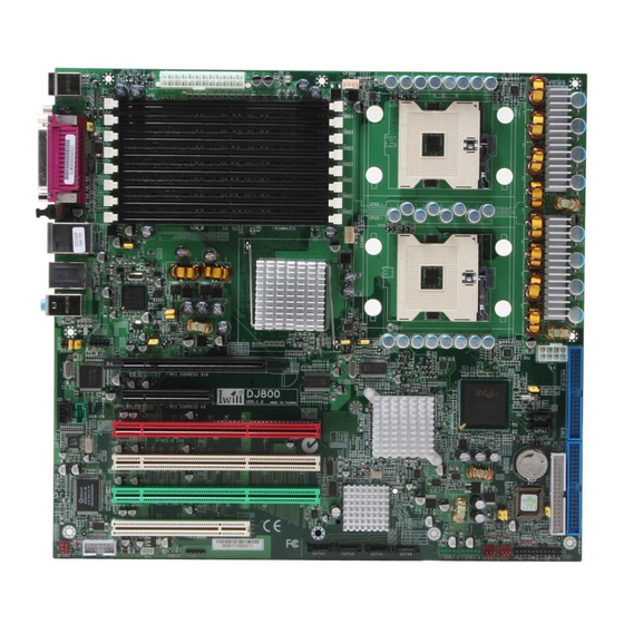
Page 14: Mainboard Map
H a r d w a r e I n s t a l l a t i o n Components and Jumper Setting D J 8 0 0 M o t h e r b o a r d MAINBOARD MAP MAINBOARD MAP J34A... -
Page 15: Components List
Components List CPU1; CPU2 Intel Xeon Socket604 Processor Primary; Secondary IDE Driver Connectors Floppy Floppy Disk Driver Connector PCI Slots PCI-Express x16, x4 Slots; PCI-X 100,133; PCI DIMM B4~A1 Memory Socket for DDR2 Memory Clear CMOS Header JP10 and JP10A Memory Voltage Select Jumper JP16 BIOS Flash Protect Jumper... -
Page 16: Jumper Setting
H a r d w a r e I n s t a l l a t i o n Components and Jumper Setting D J 8 0 0 M o t h e r b o a r d JP1: Clear CMOS Header The onboard button cell battery powers the CMOS RAM. - Page 17 JP10 and JP10A: Memory Voltage Select Jumper This header lets you adjust the memory voltage. JP10A JP10 JP16: BIOS Flash Protect Jumper This jumper protects the system from unnecessary updating or flashing of the BIOS. It secures the BIOS therefore prevents accidental overwriting of the data stored in flash memory.
-
Page 18: J57: Front Audio Jumper
H a r d w a r e I n s t a l l a t i o n Components and Jumper Setting D J 8 0 0 M o t h e r b o a r d JP19: LAN Power Select Jumper This header lets you set your LAN connectors power status. -
Page 19: Rear Panel I/O Ports
Rear Panel I/O Ports This is an illustration of the Mainboard rear I/O port array Mouse Parallel Keyboard Rear Out Center Out COM1 PS/2 Mouse Connector (6-pin Female) The system will direct IRQ12 to the PS/2 mouse if one is detected. If no mouse is detected, IRQ12 will be free for expansion cards to use. - Page 20 Components and Jumper Setting H a r d w a r e I n s t a l l a t i o n D J 8 0 0 M o t h e r b o a r d IEEE 1394/ FireWire Connector (6-pin Male) You have one (1) onboard IEEE 1394 connector port for connecting FireWire devices.
-
Page 21: Additional I/O Connectors
Additional I/O Connectors The Mainboard also contains connectors for adding additional ports and devices to the Mainboard. J43: Front Panel Switch Header Reset Button - HDD SPEAKER Reset Button (2-pin RST) This 2-pin connector connects to the chassis-mounted reset switch for rebooting your computer without turning your power switch off and on. -
Page 22: Power Led Connector
H a r d w a r e I n s t a l l a t i o n Components and Jumper Setting D J 8 0 0 M o t h e r b o a r d ACPI LED ACPI function allows the system to enter or resume from the Sus- pend mode. -
Page 23: J48: Smbus Connector
J46: WOL Connector Function This connector lets you attach a managed network adapter to the motherboard via a Wake-on-LAN cable. When the system is off, the managed network adapter uses an alternate power source to monitor the network. If it receives a wake-up packet from the server the system is remotely and automatically powered up. - Page 24 H a r d w a r e I n s t a l l a t i o n Components and Jumper Setting D J 8 0 0 M o t h e r b o a r d J63: IEEE 1394 (FireWire) Header This Mainboard features an integrated Texas Instrument TSB43AB22 chip which supports two (2) IEEE 1394 (Firewire) ports.
-
Page 25: Pin Description
J66, J67, J68, J69 Serial ATA Connector DJ800 supports up to 6 SATA devices each with data at transfer rates of 150MB/s. Two Serial ATA ports supported by ICH5R, and four Serial ATA ports supported by Adaptec 8110. Adaptec 8110 also supports RAID configurations. - Page 26 H a r d w a r e I n s t a l l a t i o n Components and Jumper Setting D J 8 0 0 M o t h e r b o a r d J34 &J34A: USB 2.0 Ports and Header DJ800 supports eight USB 2.0 ports.
-
Page 27: Eps12V Power Connectors
EPS12V Power Connectors There are two power connectors on the motherboard of the required EPS 12V power supply. These are not standard ATX connectors. DJ800 needs a minimum 460-watt EPS 12V power supply that complies with the Intel Xeon processor power supply design guidelines. Find the proper orientation of the connectors and push down firmly to make sure that the pins are aligned (the connector will only insert properly when prop- erly aligned). -
Page 28: Primary Ide Connectors
H a r d w a r e I n s t a l l a t i o n Components and Jumper Setting D J 8 0 0 M o t h e r b o a r d Primary IDE connectors The two 40-pin IDE connectors (primary and secondary channels) support 80-conductor IDE ribbon cables. -
Page 29: Cpu/ System Fan Connectors
CPU/ System Fan Connectors There are five 3-pin fan connectors in the Mainboard. Two fans are used for CPU1 and CPU2; three fans are for system and front. These connectors support cooling fans of 500mA (6W) or less. Depending on the fan manufacturer, the wiring and plug may be different. -
Page 30: Hardware Installation
Chapter 3 Hardware Installation... -
Page 31: Motherboard Installation
Motherboard Installation This section explains the basic requirements for installing the motherboard in a system housing or “chassis”. Since housing designs vary widely, you will need to consult the housing documentation for specific information. To install the motherboard in a system housing, you will need to do the following: Install a rear panel I/O shield Attach the board to the housing... -
Page 32: Installing The Cpu And Heatsink Procedures
H a r d w a r e I n s t a l l a t i o n H a r d w a r e I n s t a l l a t i o n D J 8 0 0 M o t h e r b o a r d IWILL DJ800 support Intel Xeon @FSB800 MHz processor. - Page 33 Step 3— Align the processor to the socket by matching the Pin 1 corner of the socket (marked with a triangle) to the Pin 1 corner on the Socket 604 (marked by a triangular hole in the Pin 1 corner). Align the Pin 1 corners Step 4—...
- Page 34 H a r d w a r e I n s t a l l a t i o n H a r d w a r e I n s t a l l a t i o n D J 8 0 0 M o t h e r b o a r d Step 5—...
- Page 35 Step 7— Fasten the motherboard on the chassis first. Then, place the CPU HeatSink on the top, and match the heatsink, spring and motherboard holes. Finally, please gently drive in these screws in order to fasten the heatsink. Notice: If you use the third party heaksink, it would possibly not fit our Spring installation method.
-
Page 36: Memory Installation Procedure
H a r d w a r e I n s t a l l a t i o n H a r d w a r e I n s t a l l a t i o n D J 8 0 0 M o t h e r b o a r d Installing Memory This Mainboard uses Registered DDR2 Memory with ECC or Non-... -
Page 37: Recommended Memory Configurations
Recommended Memory Configurations The following steps are our recommended DIMM installation path based on the number of DIMMS being installed (Remember to check that the DIMMS are 1.8V Registered ECC or Non-ECC DDR2 DIMMs) Memory Installation Procedures 1. Locate the Memory Bank on the Mainboard, where you will be in- stalling the DIMMs. -
Page 38: Installing Expansion Cards
H a r d w a r e I n s t a l l a t i o n H a r d w a r e I n s t a l l a t i o n D J 8 0 0 M o t h e r b o a r d Installing Expansion Cards 1. -
Page 39: Powering On Your System
Powering on your System Follow these instructions to power on the computer after you have installed the Mainboard and all system devices. 1. Be sure that all switches are off (in some systems, Off is marked by “O”). 2. After double-checking all jumper settings and connections, close the system chassis cover. -
Page 40: Bios Setup
Chapter 4 BIOS Setup... -
Page 41: Starting The Bios Setup
BIOS. The Setup program allows users to modify the basic system configuration. The BIOS is the Basic Input / Output System used in all IBM PC, XT, AT, and PS/2 compatible computers. The AMIBIOS flash chip stores the system parameters, such as type of disk drives, video displays, etc. in the CMOS. - Page 42 B I O S S e t u p D J800 M o t h e r b o a r d 1. Power on the System. Note: Normally, the only visible POST (Power On Self Test) routine is the memory test. 2.
-
Page 43: Using The Bios Setup Utility
Using the BIOS Setup Utility Navigating through the BIOS Setup Utility is straightforward. Use the arrow keys to highlight items, press <Enter> to select items in menus, and press <Esc> to quit. The following table provides more details about how to navigate in the Setup program using the keyboard. Up Arrow Key Move to the previous item Down Arrow Key... - Page 44 B I O S S e t u p D J800 M o t h e r b o a r d IMPORTANT The BIOS does NOT automatically save values that you have modified. If you do not save your values before you exit the BIOS Setup Utility, all your changes will be lost.
-
Page 45: Main Menu
Main Menu This is the first screen that is displayed when you enter the BIOS Setup Utility. Each tab lined on the top of the screen represents each different menu. The following picture shows the main menu. Main menu shows the information of BIOS version, date and ID, processor type, speed and count, and system size. -
Page 46: Advanced Menu
B I O S S e t u p D J800 M o t h e r b o a r d Advanced Menu You can make these modifications on the Advanced Menu. Select the Submenus to modify those settings. CPU Configuration IDE Configuration Floppy Configuration... -
Page 47: Boot Menu
Boot Menu Feature Description Boot Device Priority Specify the boot device priority sequence Hard Disk Drives Specify the boot device priority sequence from available hard drives Removable Drives Specify the boot device priority sequence from available removable drives CD/DVD Drives Specify the boot device priority sequence from available CD/DVD drives Chapter 4... -
Page 48: Boot Setting Configuration Submenu
B I O S S e t u p D J800 M o t h e r b o a r d Boot Setting Configuration Submenu Feature Quick Boot Quiet Boot AddOn ROM Display Mode Bootup Num-Lock PS/2 Mouse Support Typematic Rate Option Description... - Page 49 Wait for “F1” if error Hit ‘DEL’ Message Display Interrupt 19 Capture Disabled Wait for F1 key to be pressed if error occurs Enabled Display “Press DEL to run Disabled Setup” in POST Enabled Disabled Enabled: allows option ROMs to trap interrupt 19 Enabled Chapter 4...
-
Page 50: Exit Menu
B I O S S e t u p D J800 M o t h e r b o a r d Exit Menu Feature Save Changes and Exit Discard Changes and Exit Discard Changes Load Optimal Defaults Load Failsafe Defaults 4-10 Description Exit system setup after saving the... -
Page 51: Os And Drivers Installation
Chapter 5 OS and Drivers Installation... -
Page 52: Drivers Installation
OS and Drivers Installation D J800 M o t h e r b o a r d DJ800 can be run on Windows 2000, XP, and Linux (SuSe64, RedHat) system. DJ800 supports the Intel Extended Memory 64 bit Technology. It can take the full advantage of 64 bit architecture. -
Page 53: Drivers Installation
Drivers Installation On the motherboard package, you could find a Power installation CD. It contains the required drivers. 1. Audio Driver The audio driver for on board AD1980 chipset 2. Adaptec 8110 driver for the serial-ATA devices 3. Intel GbE LAN Driver 4. - Page 54 MEMO MEMO...
- Page 55 MEMO MEMO...
- Page 56 MEMO MEMO...
Need help?
Do you have a question about the Motherboard DJ800 and is the answer not in the manual?
Questions and answers