
Related Manuals for IWILL DNS-SATA


Summary of Contents for IWILL DNS-SATA
- Page 1 ’ ’ FB25633100...
- Page 2 Neither this manual, nor any of the material contained here in, may be reproduced without the express written consent of the manufacturer. IWILL ©Copyright 2004 All produce specs are subject to change without prior notice. The actual specs will be according to the actual product.
-
Page 3: Table Of Contents
Installing Expansion Cards ................- 36 - PCI-Express Riser Card..................- 37 - Serial ATA Connector..................- 38 - IDE and Floppy Connectors ................- 39 - DNS Power Supply ....................- 40 - CPU/ System Fan Connectors .................- 41 - IWILL DNS Series - 3 -... - Page 4 Main Menu......................- 48 - Advanced Menu....................- 49 - Boot Menu ......................- 50 - Boot Setting Configuration Submenu..............- 51 - Exit Menu......................- 52 - Chapter 5 ........................- 53 - Drivers Installation....................- 53 - Drivers Installation....................- 54 - - 4 - IWILL DNS Series...
-
Page 5: Chapter 1 Overview
IWILL Chapter 1 Overview IWILL DNS Series - 5 -... -
Page 6: Dns Package Content
4. Rear panel I/O shield Covers the area around the rear panel I/O ports when the board is installed in a system housing. 5. One set of SATA cables (DNS-SATA has two sets) Connector cable for onboard SATA connectors. 6. Two ATA-66/100 IDE cables Connects IDE devices to one of the onboard IDE connectors. -
Page 7: Safety Notice
Handle a board by its edges only; do not touch its components, peripheral chips, memory modules or contacts. When handling chips or modules, avoid touching their pins. IWILL DNS Series - 7 -... - Page 8 Intel Xeon @800MHz FSB Processor At least one Registered DDR memory module At least one SATA or IDE HDD EPS12V Power Supply with 460W or above Important: You must have enough system integration knowledge before the installation. - 8 - IWILL DNS Series...
-
Page 9: Getting Help
If those options don't work for you, IWILL also provides some helpful resources to help you. 1. Visit IWILL® website at Http://www.iwill.net and navigate to this product’s page which contain links to product updates such as Jumper settings or BIOS updates. -
Page 10: Dns Specifications
Supports 800MHz FSB Chipset Intel E7520 Chipset MCH Intel® 82801EB I/O Controller Hub 5 (ICH5) Intel® 6700PXH 64-bit PCI Hub (DNS/DNS-SATA Only) Winbond 83627 HF Memory 8 DIMMs for 184-pin DDR 333/266 DIMM sockets Support up to 6 DIMMs DDR333 memory... - Page 11 Hardware Monitor control by Analog Device ADM1026 System Management Fan speed control method: DC FAN Support AC power failure EATX form factor 12’’x13’’ Form Factor EEB 3.5 EPS 12V power connectors (24 pin + 8 pin) IWILL DNS Series - 11 -...
-
Page 12: Components And Jumper Setting
DNS Motherboard IWILL Chapter 2 Components and Jumper Setting - 12 - IWILL DNS Series... -
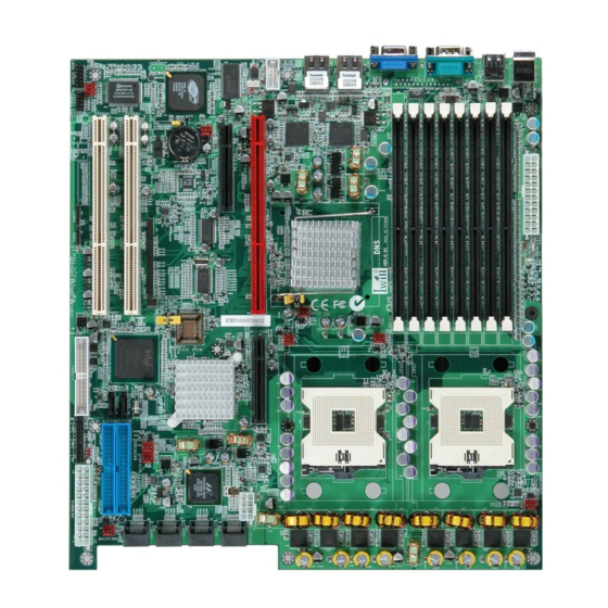
Page 13: Mainboard Map
Registered Memory PCI Hub Intel® 7520 Memory PCI-X 64bit /100MHz Marvell 88SX6041 Controller Hub (MCH) SATA controller Dual Intel® Xeon™ IPMI 2.0 Compliant processor ® RageXL Video Intel® 82801EB I/O Controller Controller Hub 5 (ICH5) IWILL DNS Series - 13 -... -
Page 14: Rear Panel I/O Ports
Plug and Play peripherals. You can connect or disconnect USB cables when the system is turned on. - 14 - IWILL DNS Series... - Page 15 • 10Mbps - will not blink • 100Mbps - LED is green • 1000Mbps - LED is orange Link and Activity LED (left) • LED is yellow when the LAN connection is linked and accessed. IWILL DNS Series - 15 -...
-
Page 16: Jumper Setting And Internal Connectors For Mainboard
COM Port (J32) Front panel switch header (J43) VGA Jumper (J20) Clear CMOS Header (JP1) LAN LED Pin Header (J105, J106) 11 BIOS Protect Jumper (JP16) IrDA Connector (J45) Chassis Intrusion Pin Header (JP22) - 16 - IWILL DNS Series... -
Page 17: Jumper Setting
This header lets you set your memory speed. Depend on the memory you choose, please adjust this jumper in order to optimize your memory utilize. Setting JP17 PLLSE0 JP21 PLLSE1 Memory Pin 1-2 Short(Default) Short(Default) DDR-333 Pin 2-3 Short Short DDR-266 JP21 JP17 IWILL DNS Series - 17 -... -
Page 18: Com Port
Pin 1 Pin4 DTR# Pin3 Pin2 Pin1 DCD# VGA Jumper This header lets you set your VGA port function. You can choose enable or disable this function or not. VCC5 Stand By VCC5 (Default) - 18 - IWILL DNS Series... -
Page 19: Lan Led Pin Header
Duplex Mode” and “Use IR Pins” fields appropriately. Driver Installation You may need to install the proper drivers in your operating system to use the IrDA function. Refer to your operating system’s manual or documentation for more information. IWILL DNS Series - 19 -... -
Page 20: Usb Headers
USB Headers DNS provides three USB pin headers on board for six USB devices. Besides, there are two more USB 2.0 ports at the rear panel. USB 2.0 supports transfer rates of up to 480MB/s. - 20 - IWILL DNS Series... -
Page 21: Bmc Card Connector
Serial/Modem and LAN connections, and the capabilities for automatic alerting and recovery. Installation Procedures 1. Before you enter in your BMC card on the DNS-SATA board, please match each pin’s position. Rear of BMC card On board 2. -
Page 22: Front Panel Connector
These functions can be configured by making appropriate settings in the Integrated Peripherals submenu (“Super IO Device” field) of the BIOS. Speaker Connector This connects to the PC speaker installed in the system chassis. - 22 - IWILL DNS Series... -
Page 23: Clear Cmos Jumper
Turn on your computer by pressing the power-on button. Hold down <F2> during boot and select either <Load Optimal Defaults> or <Load Failsafe Defaults> in the “Exit” section. Then go through the BIOS setup to re-enter user preferences. IWILL DNS Series - 23 -... -
Page 24: Jp16: Bios Protect Jumper
Chassis intrusion is a security function. This can detect whether the chassis (case) had been opened or not. If the case had been opened, the open record would show on the screen until you delete this message. Setting Function Open Disable Close Enable - 24 - IWILL DNS Series... -
Page 25: Hardware Installation
IWILL Chapter 3 Hardware Installation IWILL DNS Series - 25 -... -
Page 26: Motherboard Installation
4. Place the motherboard in the housing and align the mounting holes to the standoffs of the housing’s motherboard mounting plate. Make sure all of the rear I/O ports are properly aligned with the openings of the I/O panel. - 26 - IWILL DNS Series... - Page 27 5. Secure the motherboard to the housing by inserting mounting screws in all the holes. EEB 3.5 holes for the motherboard DNS follows the EEB 3.5 form factor. Please choose the chassis that can support EEB3.5 form factor. IWILL DNS Series - 27 -...
-
Page 28: Installing The Cpu And Heatsink Procedures
IWILL Installing the CPU and Heatsink Procedures IWILL DNS supports Intel Xeon @FSB800 MHz processor. You must insert a CPU into CPU socket 1 (CPU1) first before installing one in CPU socket 2 (CPU2). We only recommend using the Intel Original heatsink kit. CEK (Common Enabling Kit) is specially designed for the Intel latest Xeon. - Page 29 Turn over the motherboard, and let the front side to face you. Then, raise the retaining lever of the processor locking mechanism to a perpendicular position. Raise the socket lever to the vertical position IWILL DNS Series - 29 -...
- Page 30 Pin 1 corner on the Socket 604 (marked by a triangular hole in the Pin 1 corner). Align the Pin 1 corners Carefully insert the Xeon processor in the socket receptacles, taking care not to bend any pins. Insert the processor - 30 - IWILL DNS Series...
- Page 31 CPU. Do not spread the TIM around. When you place the heatsink on top of the CPU the material will disperse evenly. Apply all of the thermal interface material to the center of the processor heater spreader plate IWILL DNS Series - 31 -...
- Page 32 Place the CPU heatsink on the top, and align the heatsink, spring and motherboard holes together. Finally, please gently drive in all screws in order to fasten the heatsinks. Please follow the number sequence to drive in four screws - 32 - IWILL DNS Series...
-
Page 33: Heatsink Installation Notice
--The rim of heatsink has a fillister, and it needs the retention to fasten it. Put the attached CPU plate to the back of this motherboard Screw Retention Module on top of this motherboard Put CPU Heatsink on the top and finish the installation IWILL DNS Series - 33 -... -
Page 34: Memory Installation Procedure
DNS Motherboard IWILL Memory Installation Procedure Locate the DIMM modules Make sure the DIMM’s pins are facing down, and check that the pin arrangement on the memory module resembles the one pictured below. - 34 - IWILL DNS Series... - Page 35 PC2100/2700/3200 (DDR266/DDR333/DDR400) and Double Data Rate Memory (DDR) memory modules in 128MB, 256MB, 512MB, 1GB, and 2GB combinations. Total memory size for one mainboard is between 128MB and 16GB. Warning DNS SERIES ONLY supports Registered DDR ECC memory. IWILL DNS Series - 35 -...
-
Page 36: Installing Expansion Cards
Card Interoperability Slot Card Warning Please completely power OFF your power supply when adding or removing any expansion cards or other system components. Failure to do so may cause severe damage to both your Mainboard - 36 - IWILL DNS Series... -
Page 37: Pci-Express Riser Card
1U and 2U chassis without scarified the PCI-Express slot. Please plug this card into PCI-Express x8 and PCI-X 64/133 slot (show in red color on board). Important DNS-L still keeps PCI-X 133 slot without any bandwidth, but only for fixing PCI-Express Riser Card purpose. IWILL DNS Series - 37 -... -
Page 38: Serial Ata Connector
J80, J81, J82, J83 Serial ATAII Connector (DNS-SATA ONLY) DNS-SATA adopts Marvell chipset, and it can provide eight SATAII ports each with data transfer rates of 300MB/s. The speed of SATA II is double than the SATA devices. It uses point to point technology, and supports hot swap. -
Page 39: Ide And Floppy Connectors
Mainboard. Then, plug the other end of the ribbon into the floppy drive. Make sure you align the Pin 1 on the connector with the Pin 1 alignments on the Mainboard and the floppy drive. IWILL DNS Series - 39 -... -
Page 40: Dns Power Supply
CPUs. 24-pin Power Supply Connector 8-pin Power Supply Connector Important There are two 24 pin connectors. Please choose either one to install. DON’T plug into both connectors at the same time. - 40 - IWILL DNS Series... -
Page 41: Cpu/ System Fan Connectors
The CPU and/or motherboard will overheat if there is not enough airflow across the CPU and onboard heatsink. Damage may occur to the motherboard and/or the CPU fan if these pins are incorrectly used. These are NOT jumpers; DO NOT place jumper caps over these pins. IWILL DNS Series - 41 -... -
Page 42: Powering On Your System
Re-check your jumper settings and connections. Contact your retailer/dealer for assistance if everything else fails. 3. During power-on, hold down <F2> to enter BIOS setup. Follow the instructions in BIOS for further setup information. - 42 - IWILL DNS Series... -
Page 43: Bios Setup
IWILL Chapter 4 BIOS Setup IWILL DNS Series - 43 -... - Page 44 Click File from the menu, and then select Format. A Format 3 1/2 Floppy Disk window appears. If you are using Windows™, select “Create an MS-DOS startup disk” from the format options field, then click Start. Move the latest BIOS file to the bootable floppy disk. - 44 - IWILL DNS Series...
- Page 45 IWILL Using “AMIFLASH.EXE” to update the BIOS Update the BIOS using the AMIFLASH.EXE utility in DOS environment. 1. Visit the IWILL website ( http://www.iwill.net ) to download the latest BIOS file for your motherboard. Save the BIOS file to a bootable floppy disk.
-
Page 46: Using The Bios Setup Utility
<F2>/<F3> Key Change Colors <F7> Key Discard Changes Load Failsafe Defaults <F8> Key Load Optimal Defaults <F9> Key <F10> Key Save and Exit Home Go to Top of Screen Go to Bottom of Screen Exit - 46 - IWILL DNS Series... - Page 47 The best advice is to ONLY alter settings that you thoroughly understand. The default settings have been carefully chosen by AMIBIOS to provide the maximum system performance and reliability. Even a slight change to the chipset setup may cause potential and unpredictable failure to the system. IWILL DNS Series - 47 -...
-
Page 48: Main Menu
Due to the different BIOS versions, this BIOS screen will possibly be not exactly the same with what you see while you are setting up DNS BIOS. Please read the right description column carefully on your BIOS screen. For any further setup questions, please contact with our Technology Support staff. - 48 - IWILL DNS Series... -
Page 49: Advanced Menu
You can make these modifications on the Advanced Menu. Select the Submenus to modify those settings. CPU Configuration IDE Configuration Floppy Configuration SuperIO Configuration Hardware Health Configuration ACPI Configuration Event Log Configuration MPS Configuration PCI-Express Configuration Remote Access Configuration USB Configuration IWILL DNS Series - 49 -... -
Page 50: Boot Menu
Specify the boot device priority sequence from Hard Disk Drives available hard drives Specify the boot device priority sequence from Removable Drives available removable drives Specify the boot device priority sequence from CD/DVD Drives available CD/DVD drives - 50 - IWILL DNS Series... -
Page 51: Boot Setting Configuration Submenu
Wait for “F1” if error Enabled error occurs Disabled Display “Press DEL to run Hit ‘DEL’ Message Display Enabled Setup” in POST Disabled Enabled: allows option ROMs to Interrupt 19 Capture Enabled trap interrupt 19 IWILL DNS Series - 51 -... -
Page 52: Exit Menu
Load optimal default values for all the setup Load Optimal Defaults questions. F9 key can be used for this operation Load Failsafe default values for all the setup Load Failsafe Defaults questions. F8 key can be used for this operation - 52 - IWILL DNS Series... -
Page 53: Drivers Installation
IWILL Chapter 5 Drivers Installation IWILL DNS Series - 53 -... -
Page 54: Drivers Installation
Besides, this user’s manual will also be placed inside this the CD-ROM. If you have any question about how to install operation system, please check on IWILL website www.iwill.net or contact with our Technology Supporters. We also suggest you visit our website for downloading the latest BIOS and drivers regularly.
Need help?
Do you have a question about the DNS-SATA and is the answer not in the manual?
Questions and answers