Table of Contents
Advertisement
Quick Links
Advertisement
Table of Contents

Related Manuals for IWILL DN800


Summary of Contents for IWILL DN800
- Page 1 I W I L L DN800/DNSV M o t h e r b o a r d U s e r ’ s M a n u a l FB23634300...
- Page 2 U s e r ’ s M a n u a l D N 800 M o t h e r b o a r d...
- Page 3 This publication, including all photographs, illustrations and software, is protected under international copyright laws, with all rights reserved. Neither this manual, nor any of the material contained herein, may be re- produced without the express written consent of the manufacturer. IWILL ©Copyright 2004 Important...
-
Page 4: Table Of Contents
Overview ................1-1 Packing list ................. 1-1 Safety Notice ................1-2 DN800/DNSV Specification ............. 1-5 Components and Jumper Setting ......2-1 Mainboard Map ................2-1 Components List ................ 2-2 Jumper Setting ................2-3 Rear Panel I/O Ports .............. - Page 5 P r e f a c e BIOS Setup ................. 3-1 Starting the BIOS Setup ............4-1 Using the BIOS Setup Utility ............ 4-3 Main Menu ................. 4-5 Advanced Menu ................. 4-6 Boot Menu ................. 4-7 Boot Setting Configuration Submenu ........4-8 Exit Menu ................
-
Page 6: Overview
Chapter Overview... - Page 7 Chapter 1 Package DN800/ DNSV Motherboard Rear panel I/O shield Three jumper caps (Extra caps in case original caps get lost) One Power Installation CD (contains drivers and utilities) User’s manual One ATA-66/100 IDE cable Two SATA cables + one SATA power cable...
-
Page 8: General Safety Precautions
O v e r v i e w O v e r v i e w D N 800 M o t h e r b o a r d YOU MUST HAVE ENOUGH SYSTEM INTEGRATION KNOWLEDGE BEFORE THE INSTALLATION General Safety Precautions Keep the area around the Server clean and free of clutter. -
Page 9: Operating Precautions
Chapter 1 Use a grounded wrist strap designed to prevent static discharge. Keep all components and printed circuit boards (PCBs) in their antistatic bags until ready for use. Touch a grounded metal object before removing the board from the antistatic bag. Do not let components or PCBs come into contact with your clothing, which may retain a charge even if you are wearing a wrist strap. -
Page 10: Getting Help
2. The FAQ (Frequently Asked Questions) sections in the IWILL website are often helpful since other users often have the same questions. 3. Email us at: support@iwill.net and we will try to answer your ques- tions within 5 business days. -
Page 11: Dn800/Dnsv Specification
Uses Registered DDR266/333 with ECC or Non-ECC Memory memory Supports total system memory size of up to 8GB One x16 PCI Express slot for graphics (DN800 ONLY) Graphics ATi Rage XL VGA with 8M RAM on board Dual Gigabit Ethernet Controller... - Page 12 D N 800 M o t h e r b o a r d 34-pin Floppy Connector Internal I/O connector 4-pin CD-In audio input connector (DN800 ONLY) 2x 40-pin IDE connectors, supports up to four (4) Enhanced IDE devices IDE Bus...
-
Page 13: Components And Jumper Setting
Chapter 2 Components and Jumper Setting... -
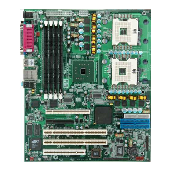
Page 14: Mainboard Map
H a r d w a r e I n s t a l l a t i o n H a r d w a r e I n s t a l l a t i o n Components and Jumper Setting D N 8 0 0 M o t h e r b o a r d... -
Page 15: Components List
Chapter 2 Components List CPU1; CPU2 Intel Xeon Socket604 Processor Primary; Secondary IDE Driver Connectors Floppy Floppy Disk Driver Connector PCI Slots PCI-Express x16, x4 Slots; PCI-X 66; PCI DIMM B2~A1 Memory Socket for DDR Memory Clear CMOS Header USB 2.0 Ports and Header Front Panel Switch Header IrDA Connector SMBus Connector... -
Page 16: Jumper Setting
H a r d w a r e I n s t a l l a t i o n H a r d w a r e I n s t a l l a t i o n Components and Jumper Setting D N 8 0 0 M o t h e r b o a r d... - Page 17 Chapter 3 J57: Front Audio Jumper This header lets you enable or disable the function of the front audio connector. W/O FRONT WITH FRONT AUDIO AUDIO CONNECTOR CONNECTOR SHORT OPEN 9-10 SHORT OPEN...
-
Page 18: Rear Panel I/O Ports
H a r d w a r e I n s t a l l a t i o n H a r d w a r e I n s t a l l a t i o n Components and Jumper Setting D N 8 0 0 M o t h e r b o a r d... - Page 19 Chapter 2 Parallel Serial COM Parallel Port Function The standard parallel port (Burgundy) is for interfacing your PC to a parallel printer. It supports SPP, ECP and EPP modes. SPP (Standard Parallel Port) Allows normal speed operation but in one direction only. ECP (Extended Capabilities Port) Allows parallel port to operate in bidirectional mode and at a speed faster than the SPP’s data transfer rate.
- Page 20 H a r d w a r e I n s t a l l a t i o n H a r d w a r e I n s t a l l a t i o n Components and Jumper Setting D N 8 0 0 M o t h e r b o a r d...
- Page 21 Chapter 2 Line-in Line-out Mic-in Audio Jack Function Line-in Jack (Light Blue) This jack is an audio input connector for an external audio source. Line-out Jack (Lime) This jack is used to connect stereo speakers for audio output. Mic-in Jack (Pink) This jack is used to connect an external microphone.
-
Page 22: Additional I/O Connectors
H a r d w a r e I n s t a l l a t i o n H a r d w a r e I n s t a l l a t i o n Components and Jumper Setting D N 8 0 0 M o t h e r b o a r d... -
Page 23: Power On Switch
Chapter 2 ACPI LED ACPI function allows the system to enter or resume from the Sus- pend mode. If your system chassis does not have this button, the same function may be performed from your OS; if it is supported. Power On Switch This switch connects to the system’s Power button allowing you to power on and off the system. -
Page 24: Driver Installation
H a r d w a r e I n s t a l l a t i o n H a r d w a r e I n s t a l l a t i o n Components and Jumper Setting D N 8 0 0 M o t h e r b o a r d... - Page 25 Chapter 2 J50: IPMI connector Function DN800 and DNSV support IPMI v1.5. The IPMI specification de- fines an internal management bus for extending platform management within a chassis. IPMI functions include remote management access over Serial/Modem and LAN connections, and the capabilities for auto- matic alerting and recovery.
- Page 26 M o t h e r b o a r d J64, J65 Serial ATA Connector DN800/DNSV supports up to 2 SATA devices each with data transfer rates of 150MB/s. It also supports RAID configurations. RAID stands for “Redundant Array of Independent Devices” and provides different levels of safety, redundancy and performance.
-
Page 27: Eps12V Power Connectors
EPS12V Power Connectors There are two power connectors on the motherboard of the required EPS 12V power supply. These are not standard ATX connectors. DN800 needs a minimum 460-watt EPS 12V power supply that complies with the Intel Xeon processor power supply design guidelines. Find the... -
Page 28: Primary Ide Connectors
H a r d w a r e I n s t a l l a t i o n H a r d w a r e I n s t a l l a t i o n Components and Jumper Setting D N 8 0 0 M o t h e r b o a r d... -
Page 29: Cpu/ System Fan Connectors
Chapter 2 CPU/ System Fan Connectors There are six 3-pin fan connectors in the Mainboard. Two fans are used for CPU1 and CPU2; four fans are for system and front. These connectors support cooling fans of 500mA (6W) or less. Depending on the fan manufacturer, the wiring and plug may be different. -
Page 30: Hardware Installation
Chapter 3 Hardware Installation... -
Page 31: Motherboard Installation
Chapter 3 Motherboard Installation This section explains the basic requirements for installing the motherboard in a system housing or “chassis”. Since housing designs vary widely, you will need to consult the housing documentation for specific information. To install the motherboard in a system housing, you will need to do the following: Install a rear panel I/O shield Attach the board to the housing... -
Page 32: Installing The Cpu And Heatsink Procedures
D N 8 0 0 M o t h e r b o a r d Installing the CPU and Heatsink Procedures IWILL DN800/DNSV support Intel Xeon @FSB800 MHz processor. We only recommend using the Intel Original heatsink kit. CEK (Common Enabling Kit) is specially designed for the Intel latest Xeon. - Page 33 Chapter 3 Step 3 — Screw this plate to the chassis you will use to install this motherboard. Please position the case mounting hole of this plate to the chassis, and use four copper standoffs to fix the iron-plate to the chassis. Match the rest screw holes and install the standoffs that come with the chassis.
- Page 34 H a r d w a r e I n s t a l l a t i o n D N 8 0 0 M o t h e r b o a r d Step 5 — Raise the retaining lever of the processor locking mechanism to a per- pendicular position.
- Page 35 Chapter 3 Step 7 — Carefully insert the Xeon processor in the socket receptacles, taking care not to bend any pins. Insert the processor Step 8 — Lower the locking mechanism’s retaining lever and secure it in place to secure the processor in the socket. Grasp the processor by the edges and gently pull upwards to insure it is properly inserted.
- Page 36 H a r d w a r e I n s t a l l a t i o n D N 8 0 0 M o t h e r b o a r d Step 9 — Apply all of the TIM in the applicator to the center of the square heat spreader plate in the middle of the CPU.
- Page 37 IMPORTANT The CEK is much heavier (0.8kg) than the previous heatsink. In or- der to give the motherboard the best protection, IWILL uses a unique backplate to sustain the mass of CEK. Important: Please gently treat mainboards while screwing the heatsink.
-
Page 38: Heatsink Installation Notice
H a r d w a r e I n s t a l l a t i o n D N 8 0 0 M o t h e r b o a r d Heatsink Installation Notice From the third party heatsink —The rim of heatsink has a fillister, and it needs the retention to fasten it. -
Page 39: Memory Installation Procedure
Chapter 3 Memory Installation Procedure Installing Memory This Mainboard uses Dual Inline Memory Modules (DIMM) for reg- istered with ECC or Non-ECC only. Four DIMM socket memory banks are available. The DIMM sockets accommodate 184-pin DDR266/333 and Double Data Rate (DDR) memory modules in 128MB, 256MB, 512MB, 1GB and 2GB size combinations. -
Page 40: Memory Installation Procedures
H a r d w a r e I n s t a l l a t i o n D N 8 0 0 M o t h e r b o a r d Memory Installation Procedures This section outlines how to install Registered PC2100/PC2700 DDR DIMMs into the Mainboard. - Page 41 Chapter 3 3. Insert the module into the DIMM socket and press down evenly on both ends firmly until the DIMM module is securely in place. (The tabs of the DIMM socket will close-up to hold the DIMM in place when the DIMM is properly installed on the socket’s bottom.) Module retaining notches Socket retaining notches...
-
Page 42: Installing Expansion Cards
Mainboard and expansion cards. IMPORTANT DN800 provides a PCI-Express x16 slot for graphic use. It provides the higher performance and greater bandwidth. DN800 does not support AGP slot, so please choose the graphic card with PCI-Express interface. -
Page 43: Powering On Your System
Chapter 3 Powering on your System Follow these instructions to power on the computer after you have installed the Mainboard and all system devices. 1. Be sure that all switches are off (in some systems, Off is marked by “O”). 2. -
Page 44: Bios Setup
Chapter 4 BIOS Setup... -
Page 45: Starting The Bios Setup
Chapter 4 BIOS Setup This chapter discusses the AMIBIOS Setup program built into the ROM BIOS. The Setup program allows users to modify the basic system configuration. The BIOS is the Basic Input / Output System used in all IBM PC, XT, AT, and PS/2 compatible computers. - Page 46 B I O S S e t u p D N 800 M o t h e r b o a r d 1. Power on the System. Note: Normally, the only visible POST (Power On Self Test) routine is the memory test. 2.
-
Page 47: Using The Bios Setup Utility
Chapter 4 Using the BIOS Setup Utility Navigating through the BIOS Setup Utility is straightforward. Use the arrow keys to highlight items, press <Enter> to select items in menus, and press <Esc> to quit. The following table provides more details about how to navigate in the Setup program using the keyboard. - Page 48 B I O S S e t u p D N 800 M o t h e r b o a r d IMPORTANT The BIOS does NOT automatically save values that you have modified. If you do not save your values before you exit the BIOS Setup Utility, all your changes will be lost.
-
Page 49: Main Menu
Due to the different BIOS versions, this BIOS screen will possibly be not exactly the same with what you see while you are setting up DN800 BIOS. Please read the right description column carefully on your BIOS screen. For any further setup questions, please contact with... -
Page 50: Advanced Menu
B I O S S e t u p D N 800 M o t h e r b o a r d Advanced Menu You can make these modifications on the Advanced Menu. Select the Submenus to modify those settings. CPU Configuration IDE Configuration Floppy Configuration... -
Page 51: Boot Menu
Chapter 4 Boot Menu Feature Description Boot Device Priority Specify the boot device priority sequence Hard Disk Drives Specify the boot device priority sequence from available hard drives Removable Drives Specify the boot device priority sequence from available removable drives CD/DVD Drives Specify the boot device priority sequence from available CD/DVD drives... -
Page 52: Boot Setting Configuration Submenu
B I O S S e t u p D N 800 M o t h e r b o a r d Boot Setting Configuration Submenu Feature Option Description Quick Boot Disabled Allows BIOS to skip tests while booting Enabled Quiet Boot Disabled: display normal... - Page 53 Chapter 4 Wait for “F1” if error Disabled Wait for F1 key to be pressed if error occurs Enabled Hit ‘DEL’ Message Disabled Display “Press DEL to run Display Enabled Setup” in POST Disabled Enabled: allows option Interrupt 19 Capture ROMs to trap interrupt 19 Enabled 3-11...
-
Page 54: Exit Menu
B I O S S e t u p D N 800 M o t h e r b o a r d Exit Menu Feature Description Exit system setup after saving the changes. Save Changes and Exit F10 key can be used for this operation Exit system setup without saving the changes. -
Page 55: Os And Drivers Installation
Chapter 5 OS and Drivers Installation... -
Page 56: Os Installation
D N 8 0 0 M o t h e r b o a r d OS Installation DN800 can be run on Windows 2000, XP, and Linux (SuSe64, RedHat) system. DN800 supports the Intel Extended Memory 64 bit Technology. In or- der to run full advantage of 64 bit, you should install OS with 64 bit architecture. -
Page 57: Drivers Installation
CD-ROM. If you have any question about how to install operation system, please check on IWILL website www.iwill.net or contact with our Technology Supporters. We also suggest you visit our website for downloading the latest BIOS and drivers regularly. - Page 58 MEMO MEMO...
- Page 59 MEMO MEMO...
- Page 60 MEMO MEMO...
- Page 61 MEMO MEMO...
- Page 62 MEMO MEMO...
- Page 63 MEMO MEMO...
- Page 64 MEMO MEMO...
Need help?
Do you have a question about the DN800 and is the answer not in the manual?
Questions and answers