Table of Contents
Advertisement
Quick Links
Advertisement
Table of Contents

Related Manuals for IWILL DN800-SATA


Summary of Contents for IWILL DN800-SATA
- Page 1 IWILL DN800-SATA/DN800-L Motherboard User’s Manual FB25633000...
- Page 2 DN800-SATA/-L Motherboard IWILL IWILL DN800-SATA/-L Series...
- Page 3 IWILL ©Copyright 2004 All produce specs are subject to change without prior notice. The actual specs will be according to the actual product. IWILL DN800-SATA/-L Series...
-
Page 4: Table Of Contents
J60A, J60B: IEEE 1394 (F ..................28 EADER DN800-SATA/-L P ......................29 OWER UPPLY ........................30 LOPPY ONNECTORS CHAPTER 3 HARDWARE INSTALLATION ..................32 .........................33 OTHERBOARD NSTALLATION ..................34 NSTALLING THE EATSINK ROCEDURES ......................41 EMORY NSTALLATION ROCEDURE ........................43 NSTALLING XPANSION ARDS ........................45 OWERING ON YOUR YSTEM IWILL DN800-SATA/-L Series... - Page 5 CHAPTER 4 BIOS SETUP ........................46 BIOS S ..............................47 ETUP BIOS S ......................49 SING THE ETUP TILITY ..............................51 .............................52 DVANCED ..............................53 ....................54 ETTING ONFIGURATION UBMENU ..............................56 CHAPTER 5 OS AND DRIVERS INSTALLATION ................57 OS I .............................58 NSTALLATION ..........................59 RIVERS NSTALLATION IWILL DN800-SATA/-L Series...
-
Page 6: Chapter 1 Overview
DN800-SATA/-L Motherboard IWILL Chapter 1 Overview IWILL DN800-SATA/-L Series... -
Page 7: Dn800-Sata/Dn800-L Package Content
IWILL User’s Manual DN800-SATA/DN800-L Package Content 1. DN800-SATA/DN800-L Motherboard Professional workstation system board 2. Three jumper caps Extra caps in case original caps get lost 3. One Power Installation CD Includes support software, drivers and bundled software utilities. 4. Rear panel I/O shield Covers the area around the rear panel I/O ports when the board is installed in a system housing. -
Page 8: Safety Notice
Do not let components or PCBs come into contact with your clothing, which may retain a charge even if you are wearing a wrist strap. Handle a board by its edges only; do not touch its components, peripheral chips, memory modules or contacts. IWILL DN800-SATA/-L Series... - Page 9 Intel Xeon @800MHz FSB Processor At least one Registered DDR2 memory module At least one SATA or IDE HDD EPS12V Power Supply with 460W or above Important: You must have enough system integration knowledge before the installation IWILL DN800-SATA/-L Series...
-
Page 10: Getting Help
If those options don't work for you, IWILL also provides some helpful resources to help you. -
Page 11: Dn800-Sata/Dn800-L Specifications
Three PCI 32/33 slots Internal I/O 1 x 34-pin Floppy Connector connector 4-pin CD-In and Aux-In audio input connector 2x 40-pin IDE connectors, supports up to four (4) Enhanced IDE devices IDE Bus Dual Channel Master Mode Ultra DMA 100/66/33 IWILL DN800-SATA/-L Series... - Page 12 Support ACPI S1 Support ASF2.0 Hardware Monitor control by ADT-7460 System Management Fan speed control method: DC FAN Support AC power failure ATX form factor Form Factor 12’’x10’’ EPS 12V power connectors (24 pin + 8 pin) IWILL DN800-SATA/-L Series...
-
Page 13: Chapter 2 Components And Jumper Setting
IWILL Components and Jumper Setting Chapter 2 Components and Jumper Setting IWILL DN800-SATA/-L Series... -
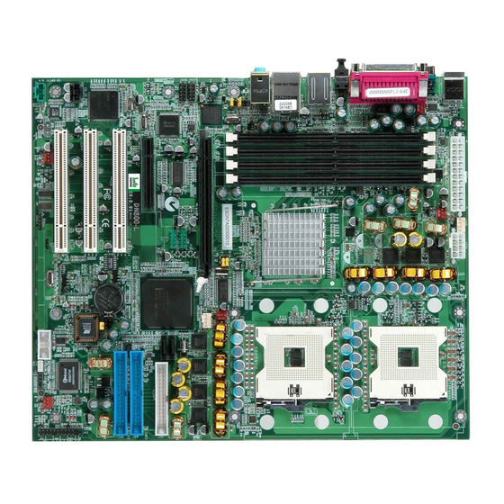
Page 14: Motherboard Layout
DN800-SATA/-L Motherboard IWILL Motherboard Layout: IWILL DN800-SATA/-L Series... -
Page 15: Components List
COM2 Port J34, J34A USB 2.0 Headers Case Open Pin Header Front Panel Connector IrDA Connector WOL Connector SMBus Connector AUX-IN CD-IN J57B Audio Jumper J58, J58A, J58B, J58C, J58D, J58E Serial ATA Connectors J60A, J60B IEEE-1394 Headers IWILL DN800-SATA/-L Series... -
Page 16: Jumper Setting
Turn on your computer by pressing the power-on button. Hold down <F2> during boot and select either <Load Optimal Defaults> or <Load Failsafe Defaults> in the “Exit” section. Then go through the BIOS setup to re-enter user preferences. IWILL DN800-SATA/-L Series... -
Page 17: Jp3; Jb3A: Fsb Jumper
Case Open is a security function. This can detect whether the chassis (case) had been opened or not. If the case had been opened, the open record would show on the screen until you delete this message. Setting Open Disable Close Enable IWILL DN800-SATA/-L Series... -
Page 18: J57: Front Audio Jumper
DN800-SATA/-L Motherboard IWILL J57: Front Audio Jumper This header lets you enable or disable the function of the front audio connector. W/O FRONT WITH FRONT AUDIO AUDIO CONNECTOR CONNECTOR SHORT OPEN 9-10 SHORT OPEN IWILL DN800-SATA/-L Series... -
Page 19: Rear Panel I/O Ports
The COM1 serial port can be used for pointing devices or other serial devices. Universal Serial Bus Ports (4-pin Female) Four onboard external USB 2.0 ports are available for connecting USB devices. Refer to USB 2.0 Ports & Header for more information. IWILL DN800-SATA/-L Series... - Page 20 Audio Jacks (Phone Jacks) The interface is supported by the onboard Analog Device AD1980. It has 3 phone jacks for Line-Out, Microphone In, and Line-In. S/PDIF Port DN800-SATA/ DN800-L also provide the S/PDIF out, Rear Out, and Center Out function. IWILL DN800-SATA/-L Series...
-
Page 21: Additional I/O Connectors
ACPI LED ACPI function allows the system to enter or resume from the Suspend mode. If your system chassis does not have this button, the same function may be performed from your OS; if it is supported. IWILL DN800-SATA/-L Series... - Page 22 Integrated Peripherals submenu (“Super IO Device” field) of the BIOS. Speaker Connector This connects to the PC speaker installed in the system chassis. Power LED Connector This connector connects to the system’s Power LED. When the system’s power is on, this LED will light. IWILL DN800-SATA/-L Series...
-
Page 23: J45: Irda Connector
Duplex Mode” and “Use IR Pins” fields appropriately. Driver Installation You may need to install the proper drivers in your operating system to use the IrDA function. Refer to your operating system’s manual or documentation for more information. IWILL DN800-SATA/-L Series... -
Page 24: J46: Color Connector
The SMBus (System Management Bus) connector is used to connect SMBus devices. It is a multiple device bus that allows multiple chips to connect to the same bus and enable each one to act as a master by initiating data transfer. IWILL DN800-SATA/-L Series... -
Page 25: Serial Ata Connector
Serial ATA Connector J58, J58A Serial ATA Connector DN800-SATA/-L supports up to 2 SATA devices each with data transfer rates of 150MB/s. Two Serial ATA ports are supported by HR with RAID 0 and 1. RAID stands for "Redundant Array of Independent Devices" and provides different levels of safety, redundancy and performance. - Page 26 Combination of RAID 0 and 1: over 4 drives, The drives are split in half RAID 10 and striped together, and the 2 new striped drives are then mirrored. IWILL DN800-SATA/-L Series...
-
Page 27: Usb Header
ORTS AND EADER DN800-SATA/-L supports eight USB 2.0 ports. Four USB 2.0 ports locate at the rear panel. They are supported by NEC chipset. Four USB 2.0 headers are for the front panel. USB 2.0 supports transfer rates of up to 480MB/s. -
Page 28: J60A, J60B: Ieee 1394 (Firewire) Header
This Mainboard features an integrated Texas Instrument TSB43AB23 chip which supports three (3) IEEE 1394 (Firewire) ports. IEEE 1394 (FireWire) supports transfer rates of up to 400MB/s. One port is installed on the on-board I/O array, and two header is for external installation. IWILL DN800-SATA/-L Series... -
Page 29: Dn800-Sata/-L Power Supply
ONNECTORS There are two power connectors on the motherboard of the required EPS 12V power supply. These are not standard ATX connectors. DN800-SATA/-L needs a minimum 460-watt EPS 12V power supply that complies with the Intel Xeon processor power supply design guidelines. Find the proper orientation of the connectors and push down firmly to make sure that the pins are aligned (the connector will only insert properly when properly aligned). -
Page 30: Ide And Floppy Connectors
Mainboard. Then, plug the other end of the ribbon into the floppy drive. Make sure you align the Pin 1 on the connector with the Pin 1 alignments on the Mainboard and the floppy drive. IWILL DN800-SATA/-L Series... - Page 31 The CPU and/or motherboard will overheat if there is not enough airflow across the CPU and onboard heatsink. Damage may occur to the motherboard and/or the CPU fan if these pins are incorrectly used. These are NOT jumpers; DO NOT place jumper caps over these pins. IWILL DN800-SATA/-L Series...
-
Page 32: Chapter 3 Hardware Installation
DN800-SATA/-L Motherboard IWILL Chapter 3 Hardware Installation IWILL DN800-SATA/-L Series... -
Page 33: Motherboard Installation
Make sure all of the rear I/O ports are properly aligned with the openings of the I/O panel. 5. Secure the motherboard to the housing by inserting mounting screws in all the holes. IWILL DN800-SATA/-L Series... -
Page 34: Installing The Cpu And Heatsink Procedures
IWILL Installing the CPU and Heatsink Procedures IWILL DN800-SATA/-L support Intel Xeon @FSB800 MHz processor. We only recommend using the Intel Original heatsink kit. CEK (Common Enabling Kit) is specially designed for the Intel latest Xeon. For installing CEK, please follow direction as below. - Page 35 Match the rest screw holes and install the standoffs that come with the chassis. Step 4--- Please align the system board and backplate together and make sure matching the heatsink, system board, and backplate holes in the same position. IWILL DN800-SATA/-L Series...
- Page 36 Step 6--Align the processor to the socket by matching the Pin 1 corner of the socket (marked with a triangle) to the Pin 1 corner on the Socket 604 (marked by a triangular hole in the Pin 1 corner). Align the Pin 1 corners IWILL DN800-SATA/-L Series...
- Page 37 Step 8--Lower the locking mechanism’s retaining lever and secure it in place to secure the processor in the socket. Grasp the processor by the edges and gently pull upwards to insure it is properly inserted. The processor shouldn’t move. Secure the CPU retaining lever IWILL DN800-SATA/-L Series...
- Page 38 CPU the material will disperse evenly. Apply all of the thermal interface material to the center of the processor heater spreader plate Important: When you only place ONE Intel Xeon processor, please put on the position of CPU1 IWILL DN800-SATA/-L Series...
- Page 39 Important: The CEK is much heavier (0.8kg) than the previous heatsink. In order to give the motherboard the best protection, IWILL uses a unique backplate to sustain the mass of CEK. Important: Please gently treat mainboards while screwing the heatsink.
- Page 40 --The rim of heatsink has a fillister, and it needs the retention to fasten it. Put the attached CPU plastic plate to the back of this motherboard Screw Retention Module on top of this motherboard Put CPU HeatSink on the top and finish the installation IWILL DN800-SATA/-L Series...
-
Page 41: Memory Installation Procedure
This Mainboard uses Registered DDR2 Memory with ECC or Non-ECC only. Please be aware of the difference between DDR and DDR2. DDR modules will NOT compatible with DDR2 slots. Don’t plug DDR modules into DN800-SATA/-L memory slots. IMPORTANT Before buying DDR2 (Double Data Rate 2) DIMMs for use with the Mainboard, it is recommended that you consult your local reseller for the best and most compatible memory to use. -
Page 43: Installing Expansion Cards
Hardware installation Installing Expansion Cards DN800-SATA/DN800-L has the PCI-Express and PCI slots that can be used for any expansion cards, such as LAN, SCSI, or Riser cards. DN800-SATA/DN800-L provides two PCI-Express slots (one with x16 bandwidth; another with x8 bandwidth) for the high-end expansion card choices. - Page 44 Important: DN800-SATA/-L provides a PCI-Express x16 slot for graphic use. It provides the higher performance and greater bandwidth than the traditional AGP slot. DN800-SATA/-L does not support AGP slot, so please choose the graphic card with PCI-Express interface. IWILL DN800-SATA/-L Series...
-
Page 45: Powering On Your System
Re-check your jumper settings and connections. Contact your retailer/dealer for assistance if everything else fails. 3. During power-on, hold down <F2> to enter BIOS setup. Follow the instructions in BIOS for further setup information. IWILL DN800-SATA/-L Series... -
Page 46: Chapter 4 Bios Setup
DN800-SATA/-L Motherboard IWILL Chapter 4 BIOS Setup IWILL DN800-SATA/-L Series... -
Page 47: Bios Setup
The CMOS information that determines the system parameters may be changed by entering the BIOS Setup utility. Power on the System. Note: Normally, the only visible POST (Power On Self Test) routine is the memory test. IWILL DN800-SATA/-L Series... - Page 48 <F2> key when “Press < F2> to enter SETUP” appears briefly at the bottom of the screen. From the main menu of the BIOS Setup Utility, you can access the other setup screens, such as the Security and Power menus. IWILL DN800-SATA/-L Series...
-
Page 49: Using The Bios Setup Utility
General Help on Setup navigation keys. <F2>/<F3> Key Change Colors <F7> Key Discard Changes <F8> Key Load Failsafe Defaults <F9> Key Load Optimal Defaults <F10> Key Save and Exit Home Go to Top of Screen Go to Bottom of Screen Exit IWILL DN800-SATA/-L Series... - Page 50 The best advice is to ONLY alter settings that you thoroughly understand. The default settings have been carefully chosen by AMIBIOS to provide the maximum system performance and reliability. Even a slight change to the chipset setup may cause potential and unpredictable failure to the system. IWILL DN800-SATA/-L Series...
-
Page 51: Main Menu
Important: Due to the different BIOS versions, this BIOS screen will possibly be not exactly the same with what you see while you are setting up DN800-SATA/-L BIOS. Please read the right description column carefully on your BIOS screen. For any further setup questions, please contact with our Technology Support staff. -
Page 52: Advanced Menu
MPS Configuration Configure Multi-Processors Table PCI-Express Configuration Configure PCI-Express support Remote Access Configuration Configure Remove Access Setting USB Configuration Configure USB Setting Onboard Device Configuration Configure onboard device, such as Silicon 3114 and NEC USB, Setting Performance Setting IWILL DN800-SATA/-L Series... -
Page 53: Boot Menu
Specify the boot device priority sequence Hard Disk Drives from available hard drives Specify the boot device priority sequence Removable Drives from available removable drives Specify the boot device priority sequence CD/DVD Drives from available CD/DVD drives IWILL DN800-SATA/-L Series... -
Page 54: Boot Setting Configuration Submenu
Force BIOS Set display mode for option AddOn ROM Display Mode Keep Current Select power on state for Bootup Num-Lock NumLock Disabled Select support PS/2 PS/2 Mouse Support Enabled mouse Slow Select keyboard typematic Typematic Rate Fast rate IWILL DN800-SATA/-L Series... - Page 55 Wait for F1 key to be pressed Wait for “F1” if error Enabled if error occurs Disabled Display “Press DEL to run Hit ‘DEL’ Message Display Enabled Setup” in POST Disabled Enabled: allows option Interrupt 19 Capture Enabled ROMs to trap interrupt 19 IWILL DN800-SATA/-L Series...
-
Page 56: Exit Menu
Load optimal default values for all the setup Load Optimal Defaults questions. F9 key can be used for this operation Load Failsafe default values for all the setup Load Failsafe Defaults questions. F8 key can be used for this operation IWILL DN800-SATA/-L Series... -
Page 57: Chapter 5 Os And Drivers Installation
IWILL OS and Drivers Installation Chapter 5 OS and Drivers Installation IWILL DN800-SATA/-L Series... -
Page 58: Os Installation
DN800-SATA/-L Motherboard IWILL OS Installation DN800-SATA/-L can be run on Windows 2000, XP, and Linux (SuSe64, RedHat, Turbo) system. DN800-SATA/-L supports the Intel Extended Memory 64 bit Technology. In order to run the full advantage of 64 bit, you should install OS with 64 bit architecture. -
Page 59: Drivers Installation
Inside the motherboard package, you could find a Power installation CD. It contains the required drivers. Inside the CD, you can find the free software “Acrobat Reader” to help you read our pdf.file. Besides, this user’s manual will also be placed inside this CD-ROM. IWILL DN800-SATA/-L Series... - Page 60 5. SATA Installation If you have any question about how to install operation system, please check on IWILL website www.iwill.net or contact with our Technology Supporters. We also suggest you visit our website for downloading the latest BIOS and drivers regularly.
Need help?
Do you have a question about the DN800-SATA and is the answer not in the manual?
Questions and answers