Table of Contents
Advertisement
Quick Links
Advertisement
Table of Contents

Related Manuals for IWILL DPX2-S320


Summary of Contents for IWILL DPX2-S320
- Page 1 DPX2-S320 User’ s Guide Overview...
- Page 2 The information in this document is subject to change without notice IWILL Corp. makes no warranty of any kind with regard to this material, including, but not limited to, the implied warranties of merchantability and fitness for a particular purpose. IWILL Corp. shall not be liable for errors contained herein or for incidental or consequential damages in connection with the furnishing, performance, or use of this material.
- Page 3 Thank you for choosing the IWILL DPX2-S320 high performance Server motherboard. The DPX2-S320 is a dual Socket-604 motherboard (M/B) based on the ATX form factor. As the latest Intel MCH E7501 with South Bridge ICH3; PCI-X Bridge P64H2 is built in the M/B, DPX2-S320 fully ® supports Intel Prestonia socket 604 processor at 400/533 MHz FSB (Front Side Bus) frequency.
-
Page 4: Features Highlight
VRM Support Integrated VRM complies to spec 9.1 ® Chipset Use the latest Intel MCH E7501 with South Bridge ICH3 chipset in the DPX2-S320 M/B. System DPX2-S320 provides six memory DIMMs Memory and supported total system memory size can Support up to 16GB. - Page 5 Supports DMI through BIOS, which allows Management hardware to communicate within a standard Interface (DMI) protocol creating higher level compatibility. PC99 The DPX2-S320 is fully compliant with the Compliant Microsoft PC99 specification at both the hardware and BIOS levels. Dimension SSI form factor-12’x13” Overview...
-
Page 6: About This User Guide
About This User Guide This manual explains how to build your system with DPX2-S320 in detail. Please follow the procedures of this User Manual carefully and pay special attention to these icons. This icon informs you for particularly important IMPORTANT details regarding the setup or maintenance of your system. -
Page 7: Getting Help
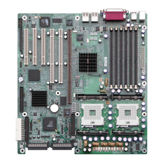
Besides these, IWILL also provides some helpful resources to help you. Select IWILL’ s website at www.iwill.net and navigate to this product page which contain links to product updates such as Jumper settings or BIOS updates. - Page 8 DPX2-S320 Motherboard (Picture) viii Overview...
- Page 9 DPX2-S320 Motherboard (Layout) Overview...
- Page 10 This page left intentionally blank for notes Overview...
-
Page 11: Hardware Installation
Chapter 1 Hardware Installation In this chapter, the installation of the DPX2-S320 with the processor and other hardware connected to your system will be explained in detail. Installation Procedures Installation procedures will be broken up into six major parts. Step 1:Jumper setting... -
Page 12: Jumper Setting
Step 1. Jumper Setting Clear COMS Header The onboard button cell battery powers the CMOS RAM. It contains all the BIOS setup information. Normally, it is necessary to keep the jumper connected to pin2 and pin3 (Default) to retain the RTC data as shown below. Note Should you want to clear the RTC data: (1) Soft off your computer... - Page 13 (5) Hold down <Delete> during bootup and select <Load Optimal Defaults> or <Load Failsafe Defaults> option in the selection “Exit”. Then re-enter BIOS setup to re-enter user preferences. BIOS...
-
Page 14: Install Memory
Step 2 Install Memory DPX2-S320 uses Dual Inline Memory Modules (DIMM). Six DIMM sockets are available for 2.5 Volts (power level), PC1600 (DDR200) and PC2100 (DDR266), Double Data Rate Memory (DDR) with 128MB, 256MB, 512MB, and 1GB combinations. And the total memory size is between 128MB and 12GB. - Page 15 Pins Pins 3. Insert the module down to the DIMM socket in with both hands and press down firmly until the DIMM module is securely in place. (The tabs of the socket will close-up to hold the DIMM in place when the DIMM touches BIOS...
- Page 16 the socket’ s bottom.) DDR-A1 DDR-B1 DDR-A2 DDR-B2 DDR-A3 DDR-B3 4.Repeat step1 to step 3 to add additional DIMM modules. IMPORTANT You have to insert two memory DIMMs in #DDR-A1 and #DDR-B1 or #DDR-A2 and #DDR-B2 or #DDR-A3 and #DDR-B3 DIMMs sockets (slots or connectors) while you install the system at the first time that you want to use it ;...
-
Page 17: Install Cpu
Step 3 Install CPU ® DPX2-S320 provides Intel Xeon Socket 604 processor at 400/533 MHz FSB CPU Installation Procedures 1. Lift up the socket lever and carefully place the Socket 604 CPU with the correct orientation as the figures are shown below 2. - Page 18 BIOS...
- Page 19 Step 4. Attach Cable to Connectors This step explains where each connector is inserted on the DPX2-S320. There will be a DPX2-S320 layout picture following each explanation indicating where the connector is inserted. The motherboard connectors are: BIOS...
-
Page 20: Table Of Contents
Item Connectors Page ATX Power Supply 1-12 Floppy Disk Drive Connector 1-13 Primary IDE Connectors 1-14 Reset Switch 1-15 SCSI Hard disk Card Activity LED 1-15 Hard Disk Activity LED 1-15 Speaker Connector 1-16 ATX Power Switch / Soft Power Switch 1-16 System Power LED 1-16... -
Page 21: Atx Power Supply
For Wake on LAN support, 5-volt Stand-by lead (+5VSB) from ATX power supply must supply at least 720mA. IMPORTANT IWILL always recommand our customers to use ATX Power that has more than 300W power capacity and is capatible with Intel ATX 2.03 specification. -
Page 22: Primary Ide Connectors
Primary IDE connectors (One 40-pin IDE) Connect the single end to the board, connect the two plugs at the other end to your hard disk(s). If you install two hard disks in the same cable, you must configure the second drive to Slave mode by setting its jumper accordingly. - Page 23 IMPORTANT Ribbon cables should always be connected with the red stripe on the Pin 1 side of the connector. IDE ribbon cable must be less than 46cm (18inches), with the second drive connector no more than 15cm (6 inches) from the first connector. BIOS...
-
Page 24: Reset Switch
Figure 4-1 Item 4 through 9 are depicted in Figure 4-1 as above. 4. Reset Switch (2-pin RST) This 2-pin connector connects to the case-mounted reset switch for rebooting your computer without turning off and on your power switch. This is a preferred method of rebooting to prolong the life of the system’ s power supply. -
Page 25: Atx Power Switch / Soft Power Switch
10. Front, Back, CPU and Aux Fan Connectors (3-pin FAN) There are eight 3-pin fan connectors in the DPX2-S320 M/B. Two fans are used for CPU1 and CPU2; six are for auxiliary power. These connectors support cooling fans of 500mA (6W) or less. -
Page 26: 11. Wake-On-Lan
WARNING The CPU and/or motherboard will overheat if there is not enough airflow across the CPU and onboard heatsink. Damage may occur to the motherboard and/or the CPU fan if these pins are incorrectly used. These are not jumpers; do not place jumper caps over these pins. NOTE The “Rotation”... - Page 27 IMPORTANT This feature requires that your system have an ATX power supply with at least 720mA +5VSB standby power. Figure 4-2 BIOS...
-
Page 28: Ps/2 Mouse Connector
USB devices. But a user cans only two of them with proper cabling for connecting USB. 15. Parallel Printer Connector (25-pin Female) You can enable the parallel port and choose the IRQ through the BIOS Setup. 16. Onboard LAN Ports DPX2-S320 integrates dual Intel 82540EM Gigabit Ethernet controllers. BIOS... -
Page 29: Serial Port Com1/2 Connectors
21. Adaptec 7902W SCSI Channels DPX2-S320 use Adaptec 7902W SCSI Chip and provides two types of common internal SCSI connectors and two connectors for SCSI devices. Please refer to the “Onboard SCSI/LAN User Guide” for further information. -
Page 30: System Health Header
22. System health Header (Two 2-pin headers and Two 3-pin headers) DPX2-S320 provides two 2-pin LED, one 3-pin LED and one 2-pin Alarm reset headers for front-panel system health status. When the CPU 1/CPU2 temperature and /CPU1/CPU2/FRONT_FAN/BACK_FAN speed is over alert threshold or the network link loss, system occur audio alarm signal to alert the network administrator. - Page 31 NOTE This header is only for IWILL 1U solution. Users may not found these LED wires in the front panel of their chassis. BIOS...
- Page 32 Header Description Normal Abnormal ALARM_RST Reset the Alarm status when abnormal situation is solved. SYS_FAIL_LED Detect if the system fail or Green normal. LAN 1 LED / Detect if the Network Flash LAN 2 LED connections of onboard LAN1/LAN2 are linking. BIOS...
-
Page 33: Install Expansion Cards
Step 5. Install Expansion Cards WARNING Power off your power supply completely when adding removing any expansion cards or other system components. Failure to do so may cause severe damage to both your motherboard and expansion cards. 1. Expansion Card Installation Procedure 1.1 Read the documentation for your expansion card and makes any necessary hardware or software setting changes, such as jumpers. - Page 34 Step 6. Powering on Your Computer 1. Be sure that all switches are off (in some systems, marked with “O”). 2. After finishing all jumper settings and connections, close the system case cover. 3. Connect the power supply cord into the power supply located on the back of your system case.
- Page 35 Note Powering Off your computer You have to first exit or shut down your operating system before switching off the power switch. For ATX power supplies, you can press the ATX power switch after exiting or shutting down your operating system.
-
Page 36: Bios Setup
Chapter 2 BIOS Setup This chapter discusses the PhoenixBIOS Setup program built into the ROM BIOS. The Setup program allows users modifying the basic system configurations according to their requirements. This special information is then stored in battery-backed RAM so that it retains the Setup information when the power is turned off. -
Page 37: Using Setup
By pressing <Del>immediately after switching the system on. If the message disappears before you respond and you still wish to enter Setup Program, restart the system from state “On” to state “Off” by pressing the "RESET" button on the system case. You may also restart the system by simultaneously pressing <Ctrl>, <Alt>, and <Delete>... - Page 38 Function F1 Key General Help on Setup navigation keys. Press <F1> key to pop up a small help window that describes the appropriate keys to use and the possible selections for the highlighted item. To exit the Help Window, press <ESC> key or <F1> key again.
-
Page 39: In Case Of Problems
In Case of Problems If after making and saving system changes with Setup, you discover that your computer no longer is able to boot, the PhoenixBIOS supports an override to the CMOS setting, which resets your system to its defaults. The other way is clear the present CMOS information. -
Page 40: Main Menu
Section 1 Main Menu To start the PhoenixBIOS Setup utility: Step 1: Turn on or reboot your system.PhoenixBIOS displays this message: Step 2: Press <F2> to enter SETUP Step 3: Pressing <F2> displays the Main Menu, which looks like this: PhoenixBIOS Setup Utility Main Advanced... -
Page 41: The Menu Bar
The Menu Bar The Menu Bar at the top of the window lists these selections: Function <F1> or <Alt-H> General Help window (See below). <Esc> Exit this menu. ? arrow keys Select a different menu. ? or ? arrow keys Move cursor up and down. - Page 42 <F6> or <+> or <Space> Select the Next Value for the field. <F9> Load the Default Configuration values for this menu. <F10> Save and exit. <Enter> Execute Command or Select P Submenu. <Alt-R> Refresh screen. To select an item, use the arrow keys to move the cursor to the field you want.
-
Page 43: The Field Help Window
The Field Help Window The help window on the right side of each menu displays the help text for the currently selected field. It updates as you move the cursor to each field. The General Help Window Pressing <F1> or <Alt-H> on any menu brings up the General Help window that describes the legend keys and their alternates: General Help Setup changes system behavior by modifying the BIOS... -
Page 44: Main Menu Selections
Main Menu Selections You can make the following selections on the Main Menu itself. Use the sub menus for other selections. Feature Options Description System Time HH:MM:SS Set the system time. System Date MM/DD/YYYY Set the system date. Diskette 1 360 kB, 5 ¼... - Page 45 labeled "Primary IDE" and "Secondary IDE." There are usually two connectors on each ribbon cable attached to each IDE connector. When you have connected two drives to these connectors, the one on the end of the cable is the Master. If you need to change your drive settings, selecting one of the Master or Slave drives on the Main Menu displays a sub-menu like this: PhoenixBIOS Setup Utility...
- Page 46 Feature Options Description Type None None = Autotyping is not able to supply 1 to 39 the drive type or end user has selected User None, disabling any drive that may be Auto installed. User = You supply the hard-disk drive information in the following fields.
- Page 47 Some older drives, however, do not use Autotyping and require selecting type User and entering a pre-defined fixed-disk type value or specifying the drive parameters separately with the User type selected. You can find the correct parameters for hard-disk drives in the drive manual or written on the casing of the drive itself.
-
Page 48: Advanced Menu
Section 2 Advanced Menu Selecting "Advanced" from menu bar on the Main Menu displays a menu like this: PhoenixBIOS Setup Utility Main Advanced Power Boot Exit Item Specific Help > Advanced Chipset Control Select the > I/O Device Configuration: operating system >... - Page 49 Use the legend keys to make your selections and exit to the Main Menu. Feature Options Description Advanced Chipset Select options Advanced Control Chipset features I/O Device Configuration Advanced Processor Select options processor Options settings DMI Event Logging Event log options Local Bus IDE adapter Enable the integrated local bus IDE adapter...
- Page 50 ? ? Advanced Chipset Control Menu Selecting "Advanced Chipset Control Menu" from menu bar on the Main Menu displays a menu like this: PhoenixBIOS Setup Utility Advanced Advanced Chipset Control Item Specific Help Graphics Aperture: 8MB] Enable memory [Disabled] Select the size of gap: the Graphics Memory Remapping [Enable]...
- Page 51 Feature Options Description Graphics Aperture Enable memory gap Enabled If enabled, turn system RAM off to free address space for use with Disabled an option card. Either a 128KB conventional memory gap, starting at 512KB, or a 1MB extended memory gap, starting at 15MB will be created in system RAM.
- Page 52 I/O Device Configuration The CPU communicates with external devices such as printers through devices called Inout/Outout (I/O) ports such as serial and parallel ports. These I/O devices require the use of system resources such as I/O addresses and interrupt lines. If these devices are Plug and Play, either the BIOS can allocate the devices during POST, or the operating system can do it.
- Page 53 ESC Exit Select Enter Select > F10 Save and Exit Menu Sub-Menu Use the legend keys to make your selections and exit to the Main Menu. Use the following chart in configuring the chipset: Feature Options Description Serial Port A: Disabled Disabled turns off the port Serial Port A:...
- Page 54 Base I/O Address If you select Enabled for the Parallel Port, choose one of these I/O addresses. Interrupts IRQ5 If you select Enabled for the Parallel Port, choose one of these IRQ7 interrupt options. Diskette Controller Disabled Enables on-board legacy diskette controller.
-
Page 55: Advanced Processor Options
Advanced Processor Options Selecting "Advanced Processor " from menu bar on the Main Menu displays a menu like this: PhoenixBIOS Setup Utility Advanced Advanced Processor Options Item Specific Help Frequency Ratio X 23 Machine Checking Enabled Select the internal Disabled frequency multiplier Fast String operations Enabled... -
Page 56: The Power Menu
Section 3 The Power Menu Selecting "Power" from the menu bar displays a menu like this: PhoenixBIOS Setup Utility Main Advanced Power Boot Exit Item Specific Help Clear CMOS flag [Disabled] Enable/Disable Onboard VGA control [Enabled] onboard devices. Onboard SCSI control [Enabled] Onboard LAN [Enabled]... - Page 57 Feature Options Description Clear CMOS Flag Enabled Enable/Disable CMOS setting Disabled Onboard VGA Enabled Enable/Disable onboard VGA control controller Disabled Onboard SCSI Enabled Enable/Disable onboard SCSI control controller Disabled Onboard Lan Enabled Enable/Disable onboard LAN1 82540EM1 82540EM controller Disabled Onboard Lan Enabled Enable/Disable onboard LAN2 82540EM1...
-
Page 58: Boot Menu
Section 4 Boot Menu After you turn on your computer, it will attempt to load the operating system (such as Windows 98) from the device of your choice. If it cannot find the operating system on that device, it will attempt to load it from one or more other devices in the order specified in the Boot Menu. - Page 59 PhoenixBIOS Setup Utility Main Advanced Power Boot Exit Item Specific Help CD-ROM Drive - Hdard Drive <Tab>, Maxtor 5T020H2-(PM) <Shift-Tab>, or Bootable Add-in Cards <Enter> selects - Removable Devices field Legacy Floppy Drives Network Boot ? ? Select Item -/+ Help Change Values F9 Setup Defaults ESC Exit...
- Page 60 Note Floppy drives are not managed on this menu as part of Removable Devices. BIOS...
- Page 61 Section 5 PIR Menu Processor Information ROM allows you to monitor your hardware status. By selecting "PIR" from the top menu like this: PhoenixBIOS Setup Utility Main Advanced Power Boot Exit Item Specific Help Select the processor’ s [A0h/A1h] This is where you Select the thermal unit [30h/31h] select which...
-
Page 62: The Exit Menu
Section 6 The Exit Menu Selecting "Exit" from the menu bar displays this menu: PhoenixBIOS Setup Utility Main Advanced Power Boot Exit Item Specific Help Exit Saving Changes Exit System Setup Exit Discarding and save your Changes changes to CMOS Load Setup Defaults Discard Changes... -
Page 63: Exit Discarding Changes
"Saving Values" or "Save Changes." Both procedures store the selections displayed in the menus in CMOS (short for "battery-backed CMOS RAM") a special section of memory that stays on after you turn your system off. The next time you boot your computer, the BIOS configures your system according to the Setup selections stored in CMOS. - Page 64 Selecting “Discard Changes” on the Exit menu updates all the selections and displays this message: CMOS values have been loaded! Press <space> to continue Save Changes Selecting “Save Changes” saves all the selections without exiting Setup. You can return to the other menus if you want to review and change your selections.
-
Page 65: Phoenix Quietboot
Chapter 3.1 Boot Utility Phoenix Boot Utilities are: * Phoenix QuietBoot™ * Phoenix MultiBoot™ Phoenix QuietBoot displays a graphic illustration rather than the traditional POST messages while keeping you informed of diagnostic problems. Phoenix MultiBoot is a boot screen that displays a selection of boot devices from which you can boot your operating system. -
Page 66: Phoenix Multiboot
screen until the end of POST, and then displays the Boot First Menu, text-based with these options: A: Load the operating system from a boot device of your choice. B: Enter Setup. C: Exit the Boot First Menu (with <Esc>) and load the operating system from the boot devices in the order specified in Setup. - Page 67 The Boot First Menu Display the Boot First Menu by pressing <Esc> during POST. In response, the BIOS first displays the message, "Entering Boot Menu ..." and then displays the Boot Menu at the end of POST. Use the menu to select any of these options: Override the existing boot sequence (for this boot only) by selecting another boot device.
-
Page 68: Bios Flash Upgrade Utility
Chapter 3 .2 BIOS Flash Upgrade Utility Phoenix Phlash gives you the ability to update your BIOS from a floppy disk without having to install a new ROM BIOS chip. Phoenix Phlash is a utility for "flashing" (copying) a BIOS to the Flash ROM installed on your computer from a floppy disk. - Page 69 Create the Crisis Recovery Diskette If the OEM or dealer from whom you purchased your system has not provided you with one, then you should create a Crisis Recovery Diskette before you use the Phlash utility. If you are unable to boot your system and successfully load the Operating System, the BIOS may have been corrupted, in which case you will have to use the Crisis Recovery Diskette to reboot your system.
- Page 70 1. Command Line Mode 2. Crisis Recovery Mode WARNING For your own protection, be sure your have a Crisis Recovery Diskette ready to use before excuting Phlash. Command Line Mode Use this mode to update or replace your current BIOS. To execute Phlash in this mode, move to the directory into which you have installed Phoenix Phlash and type the following: Phlash...
- Page 71 choose Option 8, "Boot to a previous version of DOS.") 2. When DOS displays the “Starting MS-DOS” message, press <F5>. After you press <F5>, DOS bypasses the CONFIG.SYS and AUTOEXEC.BAT files, and therefore does not load any memory managers. You can now execute Phlash. Create a Boot Diskette To bypass memory managers in DOS versions previous to 5.0, follow this recommended procedure:...
-
Page 72: Troubleshooting
Appendix A Troubleshooting The following is a checking procedure for common problem encountered during system assembly. Toubleshooting Procedure Unexpected Symptom Step 1 happens Turn-Off the system power and unplug the AC power cord, then remove all add-on cards and peripherals inclusive VGA,FDD,IDE,ATAPI device and Step 2 so on Check if all jumper setti ngs are correct (Please refer to the page... - Page 73 Continue Step 8-2 Check if POST screen displays on the monitor VGA card or monitor may be defective Step 8-1 Press <Ctrl>+<Alt><Del> key simultaneously to reboot the system Step 9-2 Check if the system can be rebooted up Keyboard is defective During system booting, press<Del>...
- Page 74 WARNING Before you insert any add-on card or hardware component in the DPX2-S320, always disconnect the power cord first. 2.Symptom checking List Symptom Check point No Power (FAN is not Make sure no short circuit exist between the rotating) motherboard and chassis Check if all jumpers are set to the default position.
- Page 75 DPX2-S320. If yes, Chang CPU to 400 FSB or memory to PC1600 (DDR200). Use speaker to determine the symptom. Memory Error Check if the memory DIMM module is inserted into DIMM socket properly. Check if different speed memory modules are mixed and used in the DPX2-S320.
-
Page 76: Symptom Report Form
Appendix B Symptom Report Form BIOS DPX2-S32 Serial versio Number CPU 1 CPU 2 DIMM 0 Brand Size Component Model DIMM 1 Brand Size Component Model DIMM 2 Brand Size Component Model DIMM 3 Brand Size Component Model PCI64-1 PCI64-2 PCI64-3 PCI 1 PCI 2... - Page 77 Onboard SCSI CH 0 Onboard SCSI CH 1 Power Model Supply Watt Number Other Devices Operatin system Symptom Description: Name: Contact email address:...
Need help?
Do you have a question about the DPX2-S320 and is the answer not in the manual?
Questions and answers