Table of Contents
Advertisement
Quick Links
Table of Content
Quick Installation ....................................................... .3
Item Checklist...............................................................................3
Before Installation........................................................................3
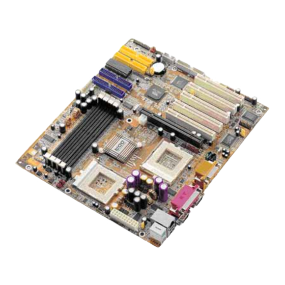
Layout...........................................................................................4
Jumpers/ Connectors..................................................................6
Feature ....................................................................... 12
Motherboard Components Placement......................................12
Block Diagram..............................................................................14
Specifications..............................................................................15
Hardware Setup ......................................................... 17
Install the Processor..................................................................17
Install Memory Modules..............................................................18
IWILL 6Channels Audio/SuperAudio(Optional)..........................19
ATX Power Supply Connector....................................................22
Back Panel...................................................................................23
FB01342420001
DVD266u-RN Version 1.0B
1
Advertisement
Table of Contents

Subscribe to Our Youtube Channel
Related Manuals for IWILL DVD266u-RN


Summary of Contents for IWILL DVD266u-RN
-
Page 1: Table Of Contents
Quick Installation ............3 Item Checklist................3 Before Installation................3 Layout...................4 Jumpers/ Connectors..............6 Feature ............... 12 Motherboard Components Placement........12 Block Diagram................14 Specifications................15 Hardware Setup ............17 Install the Processor..............17 Install Memory Modules..............18 IWILL 6Channels Audio/SuperAudio(Optional)......19 ATX Power Supply Connector............22 Back Panel...................23 FB01342420001 DVD266u-RN Version 1.0B... - Page 2 Advanced BIOS Features ............30 Advanced Chipset Features............33 Integrated Peripherals...............35 Power Management Setup............40 PnP/ PCI Configurations.............44 PC Health Status.................46 IWILL Smart Setting..............46 Load Fail Safe Defaults..............48 Load Optimized Defaults............48 Set Supervisor/ User Password Setting........49 Save & Exit Setup...............50 Exit Without Saving..............50 On board Audio ............
-
Page 3: Quick Installation
Floppy cable [ V ] Power Installer CD [ V ] 6-Channel Audio (Bracket) Optional IWILL SuperAudio (for SPDIF) USB riser kit Thermal Sensor for System Infrared port cable Before Installation Users must follow these guidelines to ensure the motherboard is protected during installation. -
Page 4: Layout
Audio VT8233 PCI3 SPDIF S M B U S RAID-IDE1 F l a s h RAID IWILL 6 CH bracket PCI4 Clear CMOS RAID-IDE0 W i n b o n d HightPoint PCI5 R E A D E R U S B 1... - Page 5 Chapter 1 Quick Installation C o n n e c t o r s / P a n e l a n d J u m p e r D e f i n i t i o n J P 1 ( C l e a r C M O S J u m p e r ) J P 6 ( K e y b o a r d P o w e r O n ) J P 7 ( D R A M V o t a g e )
-
Page 6: Jumpers/Connectors
1 2 3 Normal (Default) Clear CMOS DRAM Voltage (JP7) Normal Increase 5% Increase 10% (Default) Audio (JP8) 1 2 3 1 2 3 Enabled Disabled (Default) RAID (JP20) [DVD266u-RN only] 1 2 3 1 2 3 Enabled Disabled (Default) - Page 7 Chapter 1 Quick Installation KB_On (JP6) Tmp (J41A)/ Case (J42) J41A USB1 (J34A)/ USB2 (J34B) 2 4 6 8 10 1 3 5 7 9 IR (J45) 6 7 8 9 10 1 2 3 4 5...
- Page 8 Chapter 1 Quick Installation SPDIF & 6CH bracket (Optional) 2 4 6 8 10 12 1416 1 3 5 7 9 11 13 15 CD_IN (J54)/ AUX_IN (J53) Wake-ON-LAN (J46) 1 2 3 Wake-ON-Modem (J47) 1 2 3...
- Page 9 Chapter 1 Quick Installation CPU0 FAN (J67) FAN (J66) CPU1 FAN (J40) CPU FAN 1 2 3 System FAN(J41) 1 2 3 ATX12V (J37A) AT-PWR (J37B)
- Page 10 Chapter 1 Quick Installation ATX power connector (J37) PIN No. Definition PIN No Definition +3.3V +3.3V +3.3V -12V Ground Ground Power Supply On Ground Ground Ground Ground Ground Power Good +12V...
- Page 11 Chapter 1 Quick Installation Front panel connector (J43) F u n c t i o n P IN N O . D e fin i t i o n P W R _ O N 1 , 1 3 ( P o w e r / S o f t _ O f f ) P IN 3 : A n o d e A C P I ( A C P I L E D ) P IN 4 : C a t h o d e...
-
Page 12: Feature
Chapter2 Feature Features Motherboard Components Placement... - Page 13 C P U 0 S o c k e t System Memory Socket (DDR) On board IDE Channels AGP Pro slot IDE RAID Channels ( DVD266u-RN only) VIA VT8233 FDC connector HighPoint IDE RAID Chip (DVD266u -RN only) 5 x P C I slots...
-
Page 14: Block Diagram
Chapter2 Feature Block Diagram Dual/ Single Socket 370 CPU V I A A p o l l o P r o 2 6 6 T C h i p s e t AGP Pro Slot ( N o r t h B r i d g e ) IDE Channel x 2 PCI x 5 Keyboard &... -
Page 15: Specifications
Chapter2 Feature Specifications Processor/Socket 370 Supports Socket 370 processors Supports 133/100/66MHz FSB Supports Dual FC-PGA2 (Tualatin) Pentium III CPU with 512k/256k cache Supports Dual Pentium III (Cu-256, FC-PGA) CPU from 500MHz to 1.3GHz and higher CPU Frequency / Voltage Selection Supports Vcore selection from BIOS Supports CPU Multiplier selection by BIOS (from 2X to 12X) Supports CPU External Frequency selection by BIOS... - Page 16 Chapter2 Feature RAID Support (DVD266u-RN only) Supports ATA/100/66/33 IDE channels Supports RAID Level 0/1/0+1 Supports “ SPARE” feature Supports Win9X/WinNT /Win2k/Linx Sound Support Supports 6 Channel Speakers Management Supports Voltage monitoring Supports Fan control signal Supports Temperature sensor Supports Chassis Intrusion...
-
Page 17: Hardware Setup
Chapter 3 Hardware Setup Hardware Setup Install the Processor The CPU should have a fan attached to prevent overheating. If this is not the case, then purchase a fan before you turn on your system. Be sure that there is sufficient air circulation across the processors heatsink by regularly checking that your CPU fan is working. -
Page 18: Install Memory Modules
Chapter 3 Hardware Setup Install Memory Modules T he motherboard has three Memory sockets and supports memory size up to 3GB. Step1: Step2: Proofread the DIMM slot to have 2 Open latches of DIMM socket. No tch es, so it can fi t i n o ne direction. -
Page 19: Iwill 6Channels Audio/Superaudio(Optional)
Chapter 3 Hardware Setup IWILL 6Channels Audio/ SuperAudio (Optional) Connectors and Jumpers J P 5 A u d i o E x t e n s i o n ( D i g i t a l I / O ) C o n n e c t o r... - Page 20 Chapter 3 Hardware Setup SuperAudio(Optional) Front-Speaker SuperAudio Line-IN Game/MIDI Rear-Speaker MIC-IN Center/BASS RCA SPDIF OUT RCA SPDIF IN Optical SPDIF OUT A u d i o C a b l e Optical SPDIF IN Please remove the cap from the optical cable first...
- Page 21 Chapter 3 Hardware Setup IWILL 6Channels Audio IWILL SuperAudio (Optional)
-
Page 22: Atx Power Supply Connector
Chapter 3 Hardware Setup ATX Power Supply Connector Power on procedures STEP Description After all connections are made, close the system case over. Be sure that all switches are off. Connect the power cord into the power suppply located on the back of your system case. Connect the power cord a power outlet that is equipped with a surge protector. -
Page 23: Back Panel
Chapter 3 Hardware Setup Back Panel Function color Description This connector can be used to support PS2/Mouse Green a PS/2 mouse PS2/ This connector can be used to support Purple keyboard a PS/2 keyboard. This motherboard has two USB ports, Universal any USB-compatible peripherals Black... -
Page 24: Bios Setup
T he BIOS can be upgraded from a diskette with the Award Flash utility — AWDFLASH.EXE. T he BIOS image file, and update utility are available from IWILL’ s WEB site: sup port.iwill.net Enter BIOS setup program Power-on the system by either pressing the Power-On button, or by using any of the power-on features provided by the motherboard. - Page 25 Chapter 4 BIOS Setup Using BIOS setup program Move to the previous field Down Move to the next field Left Move to the field on the left hand side Rig ht Move to the field on the right hand side <Esc>...
-
Page 26: Main Menu
A brief description of each highlighted selection appears at the bottom of the screen. CMOS Setup Utility-Copyright(c) 1984-2001 Award Software Standard CMOS Features IWILL Smart Setting Advanced BIOS Features Load Fail-Safe Defaults Advanced Chipset Features Load Optimized Defaults... - Page 27 Chapter 4 BIOS Setup Date T his field specifies the current date. T he date format is <day>, <month>, <date>, and <year>. Time T his field specifies the current time. T he time format is <hour>, <minute>, and <second>. T he time is calculated based on the 24-ho ur (military-time) clock.
- Page 28 Chapter 4 BIOS Setup Cylinders Set the number of cylinders for this hard disk. Heads Set the number of read/write heads Precomp Setting a value of 65535 means no hard disk Sectors Set the number of sectors per track Drive A / Drive B T his field specifies the traditional type of floppy drives.
-
Page 29: Base Memory
Chapter 4 BIOS Setup Video EGA/VGA Specifies EGA or VGA adapterd (Default Value) CGA 40 Specifies CGA adapter with 40 column mode CGA 80 Specifies CGA adapter with 80 column mode MONO Specifies Monochrome adapter Halt On Each time the BIOS detects a non-fatal error, All Errors the system will stop and display an error (Default Value) -
Page 30: Advanced Bios Features
Chapter 4 BIOS Setup Advanced BIOS Features CMOS Setup Utility-Copyright(c) 1984-2001 Award Software Advanced BIOS Features [Disabled] Virus Warning Item Help CPU Internal Cache [Enabled] External Cache [Enabled] Menu Level CPU L2 Cache ECC Checking [Disabled] Quick Power On Self Test [Enabled] Allows you to choose First Boot Device... - Page 31 Chapter 4 BIOS Setup First / Second / Third / Boot Other Device T he BIOS attempts to load the operating system from the devices in the sequence selected in these items. [Floppy, LS120, HDD-0, SCSI, CDROM, HDD-1, HDD-2, HDD-3, ZIP100, USB-Z IP, USB-CDROM, USB-HDD, LAN, Disabled] Swap Floppy Drive When enabled, floppy drives A and B will be exchanged without...
- Page 32 Chapter 4 BIOS Setup Typematic Rate (Chars/Sec) When Typematic Rate Setting enabled, this field specifies how many characters will be displayed in one second when a key is held down co ntinuously. [ 6( Default Value)8,10,12,15,20,24,30]] Typematic Delay (Msec) When enabled, typematic delay allows you to select the time delay between when the key is first pressed and when the acceleration begins [250msec(Default Value)500msec,750msec,1000msec]...
-
Page 33: Advanced Chipset Features
Chapter 4 BIOS Setup Advanced Chipset Features T his setup page is used to specify advanced features available through the chipset. T he default settings have been chosen carefully for most operating conditions. DO NOT change the value of any field in this setup page without full understanding. - Page 34 Chapter 4 BIOS Setup DRAM Timing [By SPD(Default Value), Manual] DDR DRAM Cycle Length DRAM tim ing is default to AUT O, when se t to Manual, I can change DDR DRAM Cycle Leng th to 2 or 2.5. [2.5(Default Value), 2] Bank Interleave Select numbe rs o f Bank to realize fast and seam less data acce ss m ode among many different pages.
-
Page 35: Integrated Peripherals
Chapter 4 BIOS Setup Integrated Peripherals CMOS Setup Utility-Copyright(c) 1984-2001 Award Software Integrated Peripherals VIA OnChip IDE Device Item Help [Press Enter] Init Display First [AGP] OnChip USB Controller Menu Level [All Diabled] USB Keyboard Support [Disabled] IDE HDD Block Mode [Enabled] POWER ON Function [BUTTON ON]... - Page 36 Chapter 4 BIOS Setup Primary Master / Slave UDMA Second ary Master / Slave UDMA If you select Auto, the IDE controller uses Ultra DMA 33/66 Mode to access Ultra DMA-capable IDE devices. Depend on the resent of negociation with your HDD. T he maximum transfer rate of Ultra DMA 66 Mode is 66.6 MB/sec.
- Page 37 Chapter 4 BIOS Setup KB Power ON Password If you wish to use this function, bring the cursor to the field written Enter, then press <Enter>. T he computer will display the message,” Enter Password” . Type your password is displayed,re- type your password.
- Page 38 Chapter 4 BIOS Setup RxD, TxD Active When setting the field to either IrDA or ASKIR, you must select the active level of receiving and transmission signal. [Hi ,Lo(Default Value) /Lo,Hi/Lo,Lo/Hi,Hi] IR Transmission Delay When setting the field to either IrDA or ASKIR, you must select whether or not you require a d elay between IR transmissions.
- Page 39 Chapter 4 BIOS Setup ECP Mode Use DMA When the Parallel Port Mode field is configured as ECP, ECP+EPP mode, it needs a DMA channel for data transfer. T his field specifies the DMA channel for ECP parallel port use. [1:Use DMA channel 1] [3(Default Value):Use DMA channel 1] AS PWR Loss Recovery...
-
Page 40: Power Management Setup
Chapter 4 BIOS Setup Power Management Setup CMOS Setup Utility-Copyright(c) 1984-2001 Award Software Power Management Setup Power Management Option [User Define] Item Help APM HDD Power Down Timer [Disable] APM Doze Timer [Disable] Menu Level APM Suspend Timer [Disable] PM Control by APM [Yes] Video Off Option [Suspend->Off]... - Page 41 Chapter 4 BIOS Setup APM HDD Power Down Timer T his field specifies the time the system enters HDD power down. It is available only when the Power Management field is set to User Define. [1Min,2Min,3Min,4Min,5Min,6Min,7Min,8Min,9Min,10Min,11Min, 12Min,13Min,14Min,15Min, Disable(Default Value)] APM Doz Timer T his field specifies the timer value of Doze Mode.
- Page 42 Chapter 4 BIOS Setup IRQ/ Event Activity Detect T hese are I/O events whose can prevent the system from entering a power-saving mode, or can awaken the system from such a mode. In effect, the system remains alert for anything that occurs to a device configured and recognized by the system, even when the system is in a power down mode.
-
Page 43: Irqs Activity Monitoring
Chapter 4 BIOS Setup IRQs Activity Monitoring When O n, any eve nt that occurs will awaken the system after it has powered-down.T he following is a list of IRQs, or Interrupt Requests, which can be exempted much as the COM ports and LPT ports above can. When an I/O device wants to gain the attention of the operating system, it signals this by causing an IRQ to occur. -
Page 44: Pnp Os Installed
Chapter 4 BIOS Setup PnP/ PCI Configurations CMOS Setup Utility-Copyright(c) 1984-2001 Award Software PnP/PCI Configurations PNP OS Installed [No] Item Help Reset Configuration Data [Disabled] Menu Level Resources Controlled By [Auto (ESCD)] x IRQ Resources Press Enter Select Yes if you are using a Plug and Play PCI/VGA Palette Snoop [Disabled]... - Page 45 Chapter 4 BIOS Setup Resources Controlled By T he Award Plug and Play BIOS has the capacity to automatically configure all of the boot and Plug and Play compatible devices. However, this capability means absolutely nothing unless you are using a Plug and Play operating system such as Windows98/95/ NT.
-
Page 46: Pc Health Status
THE CPU IS Item Help THE CPU ID IS THE CPU EXPECT SPEED IS Menu Level CPU Micro Code Updated to Spread Spectrum =**= IWILL Micro Stepping =**= CPU Clock CPU Clock Ratio CPU0 Vcore Setting CPU1 Vcore Setting BIOS-ROM Flash Protect... - Page 47 Chapter 4 BIOS Setup Iwill MicroStepping MicroStepping Microstepping is Iwill's another step forward to provides users a fuss free CPU frequency set up procedure. It contains two main functions, Auto Detecting CPUs speed and Micro Adjustable CPU FSB speed. Auto Detecting CPU speed: IWILL MicroStepping will auto detect the CPU's factory multiplier setting and CPU FSB to the factory default.
-
Page 48: Load Fail Safe Defaults
Pressing ‘ Y’ loads the BIOS default values for the most stable, minimal-performance system operations. CMOS Setup Utility-Copyright(c) 1984-2001 Award Software Standard CMOS Features IWILL Smart Setting Advanced BIOS Features Load Fail-Safe Defaults Advanced Chipset Features... -
Page 49: Set Supervisor/ User Password Setting
Chapter 4 BIOS Setup Set Supervisor/ User Password Setting CMOS Setup Utility-Copyright(c) 1984-2001 Award Software Standard CMOS Features IWILL Smart Setting Advanced BIOS Features Load Fail-Safe Defaults Advanced Chipset Features Load Optimized Defaults Integrated Peripherals Set Supervisor Password Power Management Setup... -
Page 50: Save & Exit Setup
BIOS Setup Save & Exit Setup Saves current CMOS value and exit BIOS setup program. CMOS Setup Utility-Copyright(c) 1984-2001 Award Software Standard CMOS Features IWILL Smart Setting Advanced BIOS Features Load Fail-Safe Defaults Advanced Chipset Features Load Optimized Defaults Integrated Peripherals... -
Page 51: On Board Audio
Chapter 5 On board Audio On board Audio Audio Features Special Feature 1. Full-duplex playback and recording. Built-in 16-bit CODEC. 2. HRT F 3D positional audio, supporting both DirectSound 3D&A3D interfaces. Also supports earphones, 2/4/6 channel speakers mode. 3. Support Windows 98/Windows 2000 and Windows NT 4.0. 4.Built-in 32 OHM Earphone buffer. - Page 52 Chapter 5 On board Audio Stereo Mixer 1. Stereo analog mixing from CD-Audio and Line-in 2. Stereo digital mixing from Voice, FM/Wave-table, and Digital CD-Audio 3. Mono mixing from MIC. Software adjustable volume. Game and Midi Interface Fully compatible with MPU-401 Midi UART and Sound Blaster Midi mode/Standard IBM PC joystick/game port...
-
Page 53: Driver Installation
Chapter 5 On board Audio Driver Installation DOS Installation Before beginning the installation, please make sure that your hard disk has sufficient space(min. 4MB). Insert the Power Installer CD into the CD-ROM Drive. 1. Change directory to PCI audio DOS drivers folder (ex. - Page 54 Chapter 5 On board Audio Windows NT4.0 Installation We recommend that you have Microsoft Windows NT intalled, and remove any exsisting sound drivers from your current system, before you install this PCI sound device driver. 1. Click “ Start” , move the highlig ht bar to “ Setting” , and select the “...
-
Page 55: The Audio Rack
Chapter 5 On board Audio The Audio Rack Introduction By means of a user-friendly interface (as easy as operating your home stereo system), this PCI audio rack provides you with the control over your PC’ s audio functions, including the advantage of six speakers mode enable/ disable, and perfect digital sound ( SPDIF version ONLY) input / output. - Page 56 Chapter 5 On board Audio Mixer Volume Control For each output signal, the control slider regulates the loudness whereas a ho rizontal slid er the balance between the two s peakers . T he mute button can temporarily stop the output without changing slider positions. A button with a lit LED means the o utput is available, and vice ve rsa.
Need help?
Do you have a question about the DVD266u-RN and is the answer not in the manual?
Questions and answers