Table of Contents
Advertisement
///
Tomcat n3400B
S2925-E
Version 1.1
Copyright
®
Copyright © 2010 MiTAC International Corporation. All rights reserved. TYAN
is a
registered trademark of MiTAC International Corporation.
Trademark
All registered and unregistered trademarks and company names contained in this
manual are property of their respective owners including, but not limited to the
following.
®
TYAN
, Tomcat n3400B are trademarks of MiTAC International Corporation.
AMD, Opteron, and combinations thereof are trademarks of AMD Corporation.
AMI, AMI BIOS are trademarks of AMI Technologies.
Microsoft, Windows are trademarks of Microsoft Corporation.
SuSE is a trademark of SuSE AG.
®
Marvell
is a trademark of Broadcom Corporation and/or its subsidiaries
XGI and XG20 are trademarks of XGI Corporation
nVIDIA, nForce are trademarks of NVIDIA Corporation.
Notice
Information contained in this document is furnished by MiTAC International
Corporation and has been reviewed for accuracy and reliability prior to printing.
MiTAC assumes no liability whatsoever, and disclaims any express or implied
warranty, relating to sale and/or use of MiTAC products including liability or
warranties relating to fitness for a particular purpose or merchantability. MiTAC
retains the right to make changes to product descriptions and/or specifications at
any time, without notice. In no event will MiTAC be held liable for any direct or
indirect, incidental or consequential damage, loss of use, loss of data or other
malady resulting from errors or inaccuracies of information contained in this
document.
1
http://www.tyan.com
Advertisement
Table of Contents

Related Manuals for TYAN TOMCAT N3400B


Summary of Contents for TYAN TOMCAT N3400B
- Page 1 Tomcat n3400B S2925-E Version 1.1 Copyright ® Copyright © 2010 MiTAC International Corporation. All rights reserved. TYAN is a registered trademark of MiTAC International Corporation. Trademark All registered and unregistered trademarks and company names contained in this manual are property of their respective owners including, but not limited to the following.
-
Page 2: Table Of Contents
Page 68 3.11 Chipset Menu Page 69 3.12 Exit Menu Page 78 Chapter 4: Diagnostics Beep Codes Page 79 Flash Utility Page 79 AMIBIOS POST Code Page 80 Appendix: SMDC Information Page 83 Glossary Page 85 Technical Support Page 91 http://www.tyan.com... -
Page 3: Check The Box Contents
1 x Ultra-DMA-100/66 IDE cable cable ---- 1 x IEEE1394a Cable 1 x USB2.0 cable 1 x USB2.0 cable 1 x Tomcat n3400B user’s 1 x Tomcat n3400B user’s manual manual 1 x Tomcat n3400B Quick 1 x Tomcat n3400B Quick Reference guide... - Page 4 NOTE http://www.tyan.com...
-
Page 5: Chapter 1: Introduction Congratulations
ATA ports, is ideal for CPU, memory, and video intensive applications such as CAD, Graphics Design, and High Bandwidth Video Editing, etc. ® Remember to visit TYAN Website at http://www.TYAN.com. There you can find ® information on all of TYAN products with FAQs, online manuals and BIOS upgrades. - Page 6 Four (4) USB 2.0 ports (via cable) One (1) COM port (via cable) Power ATX 12V support, on board 4-phase TYAN® 2x9 front panel pin header One (1) 2x25 pin SMDC pin header Universal 24-pin + 8-pin power for SMDC One (1) ID LED pin header...
-
Page 7: Chapter 2: Board Installation
Chapter 2: Board Installation You are now ready to install your motherboard. The mounting hole pattern of the Tomcat n3400B S2925-E matches the ATX specification. Before continuing with installation, confirm that your chassis supports an ATX motherboard. How to install our products right… the first time The first thing you should do is reading this user’s manual. -
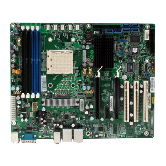
Page 8: Board Image
2.1- Board Image Tomcat n3400B S2925G2NR-E This picture is representative of the latest board revision available at the time of publishing. The board you receive may or may not look exactly like the above picture. http://www.tyan.com... - Page 9 Tomcat n3400B S2925A2NRF-E This picture is representative of the latest board revision available at the time of publishing. The board you receive may or may not look exactly like the above picture. http://www.tyan.com...
-
Page 10: Block Diagram
2.2 - Block Diagram Tomcat n3400B S2925-E Block Diagram http://www.tyan.com... -
Page 11: Board Parts, Jumpers And Connectors
2.3 - Board Parts, Jumpers and Connectors Jumper Legend OPEN - Jumper OFF, without jumper cover CLOSED – Jumper ON, with jumper cover http://www.tyan.com... - Page 12 VT6308 (1394) Enable/Disable Jumper Front Audio Header External CD-in Header J34/J35/J36/J37 Fan Connector with Tachometer CPU Fan Connector with Tachometer Fan Connector without Tachometer Fan Tachometer Header for Barebone SATA 0/1/2/3/4/5 Serial ATA RAID Connectors Aux. Power Header for PCI-E Slots http://www.tyan.com...
- Page 13 http://www.tyan.com...
- Page 14 IPMB DATA IPMB J11: External CD-in Header Use this header to connect to the external CD-in device. Pin 1 Pin 2 Pin 3 Pin 4 CDIN_L CD_GND CD_GND CDIN_R J22: SATA LED Header Pin 1 Pin 2 SATA_LED+ SATA_ACT- http://www.tyan.com...
- Page 15 http://www.tyan.com...
- Page 16 Support SMDC Card SMB_DATA LAN_SMBDA ASFDA (JP2 & JP3) J13: SMDC Connector ® The SMDC connector allows you to connect with TYAN Server Management ® Daughter Card (SMDC). The S2925-E supports TYAN SMDC M3291. See Appendix for more information on SMDC. http://www.tyan.com...
- Page 17 http://www.tyan.com...
- Page 18 Clear CMOS Replace jumper cap to close Pin_1 and 2 Reconnect Clear power supply to AC source Power on system J41: FAN Tachometer Header for Barebone Signal Signal FAN TACH1 FAN TACH2 MCP55 FANTACH FAN TACH3 FAN TACH4 FAN_PWM1 http://www.tyan.com...
- Page 19 SATA5 SATA4 SATA2/SATA3 SATA0/SATA1 http://www.tyan.com...
- Page 20 Ta chometer +12V reliable. GN D J34: FAN1, J35: FAN2, J36: FAN3, J37: FAN4 J33: CPU Fan These connectors support the tachometer monitoring and auto fan speed control. + 12V J10: FAN5 Note: J10 does not support auto fan control. http://www.tyan.com...
-
Page 21: Installing The Processor
2.4 - Installing the Processor Your brand new Tomcat n3400B S2925-E supports the latest 64-bit processor ® ® technology from AMD . Only AMD AM2 socket processors are certified and supported with this motherboard. Check our website for latest processor support. -
Page 22: Heatsink Retention Frame Installation
The following diagram will illustrate how to install the most common CPU back plates: 1. Mounting screws 2. Heatsink retention frame 3. CPU socket 4. Motherboard PCB 5. Adhesive insulator material 6. Backplate assembly NOTE: Please see next section for specific instructions on how to install mounting bracket. http://www.tyan.com... -
Page 23: Thermal Interface Material
CPU lid (applying too much will actually reduce the cooling). Always check with the manufacturer of the heatsink & processor to ensure the Thermal Interface material is NOTE compatible with the processor & meets the manufacturer’s warranty requirements http://www.tyan.com... -
Page 24: Heatsink Installation Procedures
2. After tightening screws secure metal clip to plastic retention bracket center tab. Repeat for the other side of heatsink. 3. After securing metal clip to plastic retention bracket center tab, push down on plastic clip to lock plastic clip to side tab. http://www.tyan.com... -
Page 25: Finishing Installing The Heatsink
INSTALL FAN INTO CHASSIS TO LET AIR FLOW IN!!! -To ensure that the board runs efficiently and does not overheat, make sure there is air flow around the CPU VRD (as shown) to help disperse the heat generated around the CPU. CPU VRD http://www.tyan.com... -
Page 26: Tips On Installing Motherboard In Chassis
Some chassis’ include plastic studs instead of metal. Although the plastic studs ® are usable, TYAN recommends using metal studs with screws that will fasten the motherboard more securely in place. Below is a chart detailing what the most common motherboard studs look like and how they should be installed. -
Page 27: Installing The Memory
All installed memory will automatically be detected and no jumpers or settings need changing. The Tomcat n3400B S2925-E supports up to 8GB of memory. Notes Standard DDR memory modules are not supported. Registered Memory Module is NOT supported. - Page 28 Memory Installation Procedure Follow these instructions to install memory modules into the Tomcat n3400B. Press the locking levers in the direction shown in the following illustration. Align the memory module with the socket. The memory module is keyed to fit only one way in the socket.
-
Page 29: Attaching Drive Cables
TIP: Pin 1 on the IDE cable (usually designated by a colored wire) faces the drive’s power connector. Attaching Serial ATA Cables The Tomcat n3400B S2925-E is equipped with 6 Serial ATA (SATA) channels. Connections for these drives are very simple. There is no need to set Master/Slave jumpers on SATA drives. - Page 30 Attach first floppy drive (drive A:) to the end of the cable with the twist in it. Drive B: is usually connected to the next possible connector on the cable (the second or third connector after you install Drive A:). http://www.tyan.com...
-
Page 31: Installing Add-In Cards
PCI Slot #3 AD25 INT_C INT_D INT_A INT_B (32bit) Onboard AD22 INT_C IEEE1394a Onboard AD26 INT_D YOU MUST ALWAYS unplug the power connector from the motherboard before performing system hardware changes. NOTE Otherwise you may damage the board and/or expansion device. http://www.tyan.com... -
Page 32: Connecting External Devices
PS/2 USB x 2 + USB x 2 + 10/100/1000 10/100/1000 Mouse/Keyboard LAN Port LAN Port Serial Port NOTE: Peripheral devices can be plugged straight into any of these ports but software may be required to complete the installation. http://www.tyan.com... -
Page 33: Installing The Power Supply
Yellow No Link 2.14 - Installing the Power Supply There are two power connectors on your Tomcat n3400B S2925-E. The Tomcat n3400B S2925-E requires that you have an EPS12V power supply that has a 24-pin and an 8-pin power connector. -
Page 34: Finishing Up
In the rare circumstance that you have experienced difficulty, you can find help by asking your vendor for assistance. If they are not available for assistance, please find setup information and documentation online at our website or by calling your vendor’s support line. http://www.tyan.com... -
Page 35: Chapter 3: Bios Setup
To configure the advanced chipset features PCI/PnP To configure legacy Plug & Play or PCI settings Boot To configure system boot order Security To configure user and supervisor passwords Chipset To configure chipset management features Exit To exit setup utility http://www.tyan.com... -
Page 36: Setup Basics
Chipset section unless you are absolutely sure of what you are doing. The Chipset defaults have been carefully chosen either by TYAN®® or your system manufacturer for best performance and reliability. Even a seemingly small change to the Chipset setup options may cause the system to become unstable or unusable. -
Page 37: Bios Main Menu
F10 Save and Exit System Time [22:21:21] ESC Exit System Date [Tue 03/06/2008] Feature Option Description Main Set the system time System Time HH : MM : SS System Date MM : DD : YYYY Set the system date http://www.tyan.com... -
Page 38: Advanced Menu
APM Configuration Menu Item Section for APM configuration Mark as read, Clear or View Event Log Configuration Menu Item Event Log statistics Hardware Health Configure/monitor the Menu Item Configuration Hardware Health Remote Access Configuration Menu Item Configure Remote Access http://www.tyan.com... -
Page 39: Cpu Configuration
↑↓ Select Item Maximum FSB Multiplier: xxxx Change Able to change Freq.: Option uCode Patch Level: xxxx General Help GART Error Reporting [Disabled] F10 Save and Microcode Update [Enabled] Exit Secure Virtual Machine Mode [Enabled] ESC Exit AMD Overclocking Configuration http://www.tyan.com... - Page 40 Disabled for normal operation. The driver GART Error Reporting developer may enable it for the Enabled purpose of testing. Enabled Microcode Update Enable CPU Microcode update Disabled Enabled Secure Virtual Machine Enable/disable Secure Virtual Mode Machine Mode (SVM) Disabled http://www.tyan.com...
- Page 41 AMD Overclocking Configuration Auto x4.0 800MHz x4.5 900MHz x5.0 1000MHz x5.5 1100MHz Reserved x6.5 1300MHz Reserved Processor Frequency Select processor frequency Multiplier multiplier x7.5 1500MHz x8.0 1600MHz x8.5 1700MHz x9.0 1800MHz X9.5 1900MHz x10.0 2000MHz x10.5 2100MHz x11.0 2200MHz http://www.tyan.com...
- Page 42 1.350V 1.325V 1.300V 1.275V 1.250V 1.225V 1.200V 1.175V 1.150V 1.125V 1.100V 1.075V Processor Voltage Select processor voltage 1.050V 1.025V 1.000V 0.975V 0.950V 0.925V 0.900V 0.875V 0.850V 0.825V 0.800V Auto http://www.tyan.com...
- Page 43 Enable/Disable device write protection. Disabled This will be effective only if device is Hard Disk Write Protect Enabled accessed through BIOS. IDE Detect Time Out 0~35 Select the time out value for detecting (Sec) (at 5 interval) ATA/ATAPI device(s). http://www.tyan.com...
- Page 44 ← → Select Screen ↑↓ Select Item Change Option General Help F10 Save and Exit ESC Exit Feature Option Description nVidia RAID Setup Disabled While entering setup, you can nVidia RAID Function choose enabled/disabled RAID Enabled mode for each ATA channel. http://www.tyan.com...
- Page 45 S.M.A.R.T (Self-Monitoring Analysis Auto and Reporting Technology) is a S.M.A.R.T. Disabled utility that monitors your disk status Enabled to predict hard disk failure. Enabled Enables 32-bit to maximize the IDE 32Bit Data Transfer hard disk data transfer rate. Disabled http://www.tyan.com...
- Page 46 S.M.A.R.T (Self-Monitoring Analysis Auto and Reporting Technology) is a S.M.A.R.T. Disabled utility that monitors your disk status Enabled to predict hard disk failure. Enabled Enables 32-bit to maximize the IDE 32Bit Data Transfer hard disk data transfer rate. Disabled http://www.tyan.com...
- Page 47 720 KB 31/2” connected to the system. 1.44 MB 31/2” 2.88 MB 31/2” Disabled 360 KB 51/4” Selects the type of floppy drive 1.2 MB 51/4” Floppy B connected to the system. 720 KB 31/2” 1.44 MB 31/2” 2.88 MB 31/2” http://www.tyan.com...
- Page 48 Start at PowerON. Stop at OS POST Watchdog Mode boot. OS: OS boot Watchdog. Start at OS boot. Power ON PowerON: Start at PowerON. Watchdog timer sets 2/4/6/8/10/12 Watchdog Timer minutes. When WD time-out occurs, system will auto reboot. http://www.tyan.com...
- Page 49 Main Advanced PCI/PnP Boot Security Chipset Exit Enable ACPI ACPI Settings Configuration settings General ACPI Configuration Advanced ACPI Configuration ← → Select Screen Chipset ACPI Configuration ↑↓ Select Item Change Option General Help F10 Save and Exit ESC Exit http://www.tyan.com...
- Page 50 F10 Save and Exit ESC Exit Feature Option Description General ACPI Configuration Auto Select the ACPI state used for system Suspend Mode S1 (POS) suspend. S3 (STR) Report Video on S3 Determine whether to invoke VGA BIOS Resume POST on S3/STR resume. http://www.tyan.com...
- Page 51 Note: OEMB table is used to pass Disabled POST data to the AMI code during ACPI O/S operations. Enabled Enable disable Headless Headless mode operation mode through ACPI. Disabled Enabled Enable or disable the building of ACPI SRAT Table ACPI SRAT Table Disabled http://www.tyan.com...
- Page 52 MCP55 ACPI HPET TABLE [Disabled] ← → Select Screen ↑↓ Select Item Change Option General Help F10 Save and Exit ESC Exit Feature Option Description Chipset ACPI Configuration Disabled ACPI High Precision Event Timer MCP55 ACPI HPET TABLE description table. Enabled http://www.tyan.com...
-
Page 53: Apm Configuration
Enabled Disabled Enable/Disable RTC event to wake Resume On RTC Alarm after a power failure. Enabled Last State Configures how the system board Restore on AC Power Loss Power on responds to a power failure. Power off http://www.tyan.com... - Page 54 ESC Exit Feature Option Description Event Logging details Views all unread events on the View Event Log Event Log. Marks all unread events as Mark All Events as Read read. Cancel Erases all of events. Clear Event Log Cancel http://www.tyan.com...
- Page 55 F10 Save and Exit Ambient (Near SATA0) Temp :xx C/ xxx F ESC Exit Ambient (Near MCP55) Temp :xx C/ xxx F CPU FAN Speed :xxxx RPM FAN Speed 1 :xxxx RPM FAN Speed 2 :xxxx RPM FAN Speed 3 :xxxx RPM http://www.tyan.com...
- Page 56 Disabled: Fan Power On. Auto FAN Power Enabled: Fan Power Duty Cycle=30%(40° Control Disabled 100%(60°C), see max (CPU, MCP55) temperature Enabled FAN Fail LED Enabled: Any FAN speed less than 800 Indicator RPM, the FAN Fail LED will be lighted. Disabled http://www.tyan.com...
- Page 57 ↑↓ Select Item Vdimm : x.xxx V Change Option Vcore : x.xxx V Tab Select Field +3.3 Vin : x.xxx V General Help +5 Vin : x.xxx V F10 Save and Exit +12 Vin : x.xxx V ESC Exit http://www.tyan.com...
- Page 58 115200 8,n,1 57600 8,n,1 Serial Port Mode Select Serial Port settings. 19200 8,n,1 9600 8,n,1 None Select Flow Control for console Flow Control Hardware redirection. Software Disable: Turns off the redirection Redirection After BIOS Disabled after POST POST Boot Loader: http://www.tyan.com...
- Page 59 VT-UTF8 Enable VT-UTF8 Combination key Enabled VT-UTF8 Combo Key Support for ANSI/VT100 terminals. Support Disabled Gives the delay in seconds to No Delay display memory information Delay 1 Sec Sredir Memory Display Delay Delay 2 Sec Delay 4 Sec http://www.tyan.com...
- Page 60 Hi Speed USB 2.0 Controller Mode (480Mbps) or Full Speed Full Speed (12Mbps). This is a work around for OSes Enabled without EHCI hand-off support. BIOS EHCI Hand-Off The EHCI ownership change Disabled should claim by EHCI driver. http://www.tyan.com...
- Page 61 Boot Security Chipset Exit AMD PowerNow Configuration ← → Select Screen ↑↓ Select Item Power Now [Enabled] Change Option General Help F10 Save and Exit ESC Exit Feature Option Description AMD PowerNow Configuration Enabled Power Now Enable/Disable PowerNow Disabled http://www.tyan.com...
- Page 62 PCI Express → Primary Graphics Configure primary graphics adapter. Adapter PCI → PCI Express Disabled Load PMU firmware Enabled Auto USB 1.1/2.0 Enabled/Disabled LAN controller Controller Disabled Auto LAN1/LAN2 Configure LAN1/LAN2 Disabled Disabled Onboard LAN Enable/Disable LAN PXE ROM OPROM Enabled http://www.tyan.com...
-
Page 63: Pci Pnp Menu
Clear NVRAM [No] Change Option General Help Plug & Play O/S [No] F10 Save and Exit PCI Latency Timer [64] ESC Exit PCI Bus Scan Order [Absent] Allocate IRQ to PCI VGA [Yes] Palette Snooping [Disabled] PCI IDE BusMaster [Disabled] http://www.tyan.com... - Page 64 Enabled: informs the PCI devices that an ISA graphics device is Enabled installed in the system so the card will function correctly. Disabled Enabled: BIOS uses PCI bus PCI IDE BusMaster mastering for reading / writing to Enabled IDE drives. Reserved http://www.tyan.com...
-
Page 65: Boot Menu
← → Select Screen Keyboard Error Report [Disabled] Wait for ‘F1’ if Error [Enabled] ↑↓ Select Item Hit ‘DEL’ Message Display [Enabled] Change Option Interrupt 19 Capture [Enabled] General Help F10 Save and Exit Endless Boot [Disabled] ESC Exit http://www.tyan.com... - Page 66 Disabled Enabled Displays “Press DEL to run Setup” in Hit ‘DEL’ Message Display POST. Disabled Disabled Enabled: allows option ROMs to trap Interrupt 19 Capture interrupt 19. Enabled Enabled Enable/Disable endless loop boot from Endless Boot BBS table. Disabled http://www.tyan.com...
-
Page 67: Boot Device Priority
↑↓ Select Item Change Option General Help F10 Save and Exit ESC Exit Feature Option Description Boot Device Priority Settings for boot priority. xx,xxx-xxxxx:xxx 1st Boot Device These can be customized xx,xxx-xxxxx:xxx 2nd Boot Device depending on your Disabled preference. http://www.tyan.com... -
Page 68: Security Menu
User Password. When it is set to [Enabled], BIOS Disabled will issue a virus warning Boot Sector Virus Protection message and beep if a write to the boot sector or the partition Enabled table of the HDD is attempted. http://www.tyan.com... -
Page 69: Chipset Menu
Options for NB Advanced Chipset Settings ← → Select Screen WARNING: Setting wrong values in below sections may cause system to malfunction. ↑↓ Select Item Enter Go to Sub Screen Northbridge Configuration General Help F10 Save and Exit ESC Exit http://www.tyan.com... - Page 70 NorthBridge Chipset Configuration 0.850V 1.050V 1.025V 1.000V 0.975V Specify the alternate VID while in low 0.950V Alternate VID power status. 0.925V 0.900V 0.875V 0.825V 0.800V Auto It shows the clock frequency of the Memory CLK Read only installed SDRAM. http://www.tyan.com...
- Page 71 Auto uses hardware compensation values. Other values add to or subtract Read only RAS/RAS Delay (Trrd) from hardware generated value. Recommended setting is Auto. Bits 7-4. RAS#-active to RAS#-active Row Cycle (Trc) Read only or auto refresh of the same bank. http://www.tyan.com...
- Page 72 DRAM controllers DCT Unganged Mode Auto: Configured to a single dual- Auto channel DRAM Controller Enabled Enable or disable DDR power down Power Down Enable mode Disabled Channel Power Down Mode Set DDR power down mode Chip Select http://www.tyan.com...
- Page 73 DRAM SCRUB REDIRECT allows Disabled DRAM SCRUB the system to correct DRAM ECC REDIRECT errors immediately when they occur, Enabled even if background scrubbing is on. Enable 4-Bit ECC Mode. Disabled 4-Bit ECC Mode Note: Also known as CHIPKILL ECC Mode Enabled http://www.tyan.com...
- Page 74 655.4us 1.31ms 2.62ms 5.24ms 10.49ms 20.97ms 42.00ms 84.00ms Disabled 40ns 80ns 160ns 320ns 640ns 1.28us Allows the L1 Data Cache RAM to 2.56us Data Cache BG Scrub be corrected while idle. 5.12us 10.2us 20.5us 41.0us 81.9us 163.8us 327.7us 655.4us http://www.tyan.com...
- Page 75 Disabled 40ns 80ns 160ns 320ns 640ns 1.28us Allows the L2/L3 Data Cache RAM to be corrected while idle. 2.56us L2 /L3 Cache BG Scrub 5.12us 10.2us 20.5us 41.0us 81.9us 163.8us 327.7us 655.4us http://www.tyan.com...
- Page 76 SPDs. If Limit, the DRAM speed will not exceed the specified value. If Manual, the DRAM speed specified Manual will be programmed by users. Auto DCT 0 Allow users to configure the DRAM DRAM Timing Mode Timing manually. DCT 1 Both http://www.tyan.com...
- Page 77 Disabled AGP, or disable altogether. Some 32 MB OSes require valid GART for proper 64 MB operation, If AGP is present, select IOMMU Mode 128 MB appropriate option to ensure proper 256 MB AGP operation. 512 MB 1 GB http://www.tyan.com...
-
Page 78: Exit Menu
Use this option to load default performance setup values. Use this option when system CMOS values have been corrupted or modified incorrectly. Load Failsafe Defaults Use this option to load all default failsafe setup values. Use this option when troubleshooting. http://www.tyan.com... -
Page 79: Chapter 4: Diagnostics
Every BIOS file is unique for the motherboard it was designed for. For Flash Utilities, BIOS downloads, and information on how to properly use the Flash Utility ® with your motherboard, please check the TYAN web site: http://www.TYAN.com/ NOTE: Please be aware that by flashing your BIOS, you agree that in the event of a BIOS flash failure, you must contact your dealer for a replacement BIOS. -
Page 80: Amibios Post Code
ADM module for initialization. Initialize language and font modules for ADM. Activate ADM module. Initializes the silent boot module. Set the window for displaying text information. Displaying sign-on message, CPU information, setup key message, and any OEM specific information. http://www.tyan.com... - Page 81 Wait for user input at config display if needed. Uninstall POST INT1Ch vector and INT09h vector. Deinitializes the ADM module. Prepare BBS for Int 19 boot. End of POST initialization of chipset registers. Save system context for ACPI. Passes control to OS Loader (typically INT19h). http://www.tyan.com...
- Page 82 NOTE http://www.tyan.com...
-
Page 83: Appendix: Smdc Information
Platform Management Bus (IPMB), Emergency Management Port (EMP) and standard IPMI-Over-LAN communication as defined in latest IPMI 1.5 specification. ® ® TYAN SMDC is compatible with all IPMI-compliance software as well as TYAN System Operator (TSO) software package. ® By adding SMDC, TYAN server board becomes a highly manageable and IPMI compatible system with all the advanced features suggesting in IPMI Spec. - Page 84 ® Features of TYAN Server Management Monitor various system components remotely - such as fans, processor temperature, and more Remote power on and power off Console redirect -the ability to view system remotely Alert and error actions -such as audible beep, e-mail, power down and reboot...
-
Page 85: Glossary
(reading to or writing from a disk drive a single time is much faster than doing so repeatedly) there is the possibility of losing your data should the system crash. Information in a buffer is temporarily stored, not permanently saved. http://www.tyan.com... - Page 86 DRAM (Dynamic RAM): widely available, very affordable form of RAM which looses data if it is not recharged regularly (every few milliseconds). This refresh requirement makes DRAM three to ten times slower than non-recharged RAM such as SRAM. http://www.tyan.com...
- Page 87 ROM chip which can, unlike normal ROM, be updated. This allows you to keep ® up with changes in the BIOS programs without having to buy a new chip. TYAN ’s BIOS updates can be found at http://www.TYAN®.com ESCD (Extended System Configuration Data): a format for storing information about Plug-n-Play devices in the system BIOS.
- Page 88 RAID level 1 also allows for faster access time and fault-tolerance, since either hard drive can be read at the same time. RAID level 0+1 is both striping and mirroring, providing fault-tolerance, striping, and faster access all at the same time. http://www.tyan.com...
- Page 89 USB (Universal Serial Bus): a versatile port. This one port type can function as a serial, parallel, mouse, keyboard or joystick port. It is fast enough to support video transfer, and is capable of supporting up to 127 daisy-chained peripheral devices. http://www.tyan.com...
- Page 90 CPUs without damaging the sensitive CPU pins. The CPU is lightly placed in an open ZIF socket, and a lever is pulled down. This shifts the processor over and down, guiding it into the board and locking it into place. http://www.tyan.com...
-
Page 91: Technical Support
1. See the beep codes section of this manual. ® 2. See the TYAN website for FAQ’s, bulletins, driver updates, and other information: http://www.TYAN.com ® 3. Contact your dealer for help BEFORE calling TYAN ® 4. Check the TYAN user group: alt.comp.periphs.mainboard.TYAN Returning Merchandise for Service During the warranty period, contact your distributor or system vendor FIRST for any product problems. - Page 92 Danger of explosion if battery is incorrectly replaced. Replace only with the same or equivalent type recommended by manufacturer. Dispose of used battery according to manufacturer instructions and in accordance with your local regulations. Document #: D1971-110 http://www.tyan.com...
Need help?
Do you have a question about the TOMCAT N3400B and is the answer not in the manual?
Questions and answers