Table of Contents
Advertisement
Quick Links
Thunder n6550EX
Copyright
Copyright © MiTAC International Corporation, 2008. All rights reserved. No part
of this manual may be reproduced
or translated without prior written consent from MiTAC International Corporation.
Trademark
All registered and unregistered trademarks and company names contained in
this manual are property of their respective owners including, but not limited to
the following.
®
TYAN
, Thunder n6550EX are trademarks of MiTAC International Corporation.
®
AMD
,Opteron™, and combinations thereof are trademarks of AMD
Corporation.
®
®
AMI
, AMIBIOS
Technologies.
®
Microsoft
, Windows
®
Nvidia
and nForce
®
®
®
IBM
, PC
, AT
, PS/2
®
Winbond
is a trademark of Winbond Electronics Corporation.
Notice
Information contained in this document is furnished by MiTAC International
Corporation and has been reviewed for accuracy and reliability prior to printing.
MiTAC assumes no liability whatsoever, and disclaims any express or implied
warranty, relating to sale and/or use of TYAN
warranties relating to fitness for a particular purpose or merchantability. MiTAC
retains the right to make changes to product descriptions and/or specifications
at any time, without notice. In no event will MiTAC be held liable for any direct
or indirect, incidental or consequential damage, loss of use, loss of data or other
malady resulting from errors or inaccuracies of information contained in this
document.
, and combinations thereof are trademarks of AMI
®
are trademarks of Microsoft Corporation.
®
are trademarks of Nvidia Corporation.
®
are trademarks of IBM Corporation.
Version 1.2
®
products including liability or
S4989
Advertisement
Table of Contents

Related Manuals for TYAN Thunder n6550EX


Summary of Contents for TYAN Thunder n6550EX
- Page 1 All registered and unregistered trademarks and company names contained in this manual are property of their respective owners including, but not limited to the following. ® TYAN , Thunder n6550EX are trademarks of MiTAC International Corporation. ® ,Opteron™, and combinations thereof are trademarks of AMD Corporation. ®...
- Page 2 http://www.tyan.com...
-
Page 3: Table Of Contents
Getting Help..................82 In Case of Problems ................82 BIOS Main Menu .................. 83 BIOS Advanced Menu ................84 PCI PnP Menu..................104 Boot Menu ..................106 4.10 Security Menu..................111 4.11 Chipset Menu ..................112 4.12 Exit Menu................... 125 http://www.tyan.com... - Page 4 Chapter 5: Diagnostics 5.1 Beep Codes..................127 5.2 Flash Utility ..................127 5.3 AMIBIOS Post Code ................128 Appendix: How to Make a Driver Diskette Glossary Technical Support http://www.tyan.com...
-
Page 5: Before You Begin
The retail motherboard package should contain the following: 1x S4989-SI Motherboard 6 x SATA Cable 2 x SAS to Backplane Cable 4 x CPU backplane 1 x S4989 User’s manual 1 x S4989 Quick reference guide ® 1 x TYAN Driver CD 1 x I/O shield http://www.tyan.com... - Page 6 http://www.tyan.com...
-
Page 7: Chapter 1: Instruction
SATA II flavor. All of this provides the Thunder n6650EX (S4989) the power and flexibility to meet the needs of nearly any server application. ® Remember to visit TYAN ’s Website at http://www.tyan.com. There you can find ® information on all of TYAN ’s products with FAQs, online manuals and BIOS upgrades. -
Page 8: Software Specifications
Stacked connector for (2) USB 2.0 ● Stacked connector for VGA+COM ● (3) RJ-45 connectors, side by side ● 1.3 - Software Specifications For OS (operation system) support, please check with Tyan support for latest information. http://www.tyan.com... -
Page 9: Chapter 2: Board Installation
Unplug the power from your computer power supply and then touch a safely grounded object to release static charge (i.e. power ® supply case). For the safest conditions, TYAN recommends wearing a static safety wrist strap. (2) Hold the motherboard by its edges and do not touch the bottom of the board, or flex the board in any way. -
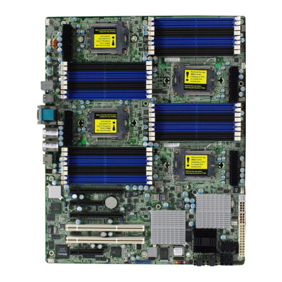
Page 10: Board Image
2.1- Board Image This picture is representative of the latest board revision available at the time of publishing. The board you receive may or may not look exactly like the above picture. http://www.tyan.com... -
Page 11: Block Diagram
2.2 - Block Diagram Thunder n6650EX (S4989) Block Diagram http://www.tyan.com... -
Page 12: Board Parts, Jumpers And Connectors
This diagram is representative of the latest board revision available at the time of publishing. The board you receive may not look exactly like the above diagram. But for the DIMM number please refer to the above placement for memory installation. For the latest board revision, please visit: http: //www.tyan.com http://www.tyan.com... - Page 13 IPMB Pin Header PCI-E configuration selection PCI-X clock frequency 133/100 JP22 MHz selection Jumper Legend OPEN - Jumper OFF Without jumper cover CLOSED - Jumper ON With jumper cover To indicate the location of pin-1 To indicate the location of pin-1 http://www.tyan.com...
- Page 14 Put jumper cap back to Pin_1 and Pin_2 (default setting) Use jumper cap to close Pin_2 and Pin_3 Pin_1 Pin_3 for several seconds to Clear Clear CMOS CMOS Reconnect power & power on system http://www.tyan.com...
- Page 15 J9: Front panel Header for Barebones Systems Signal Signal LAN1_LED+ LAN1_LED- LAN2_LED+ LAN2_LED- LAN3_LED+ LAN3_LED- ID_LED+ ID_LED- ID_S/W+ ID_S/W- RSVD J18: LCM Pin Header Signal Signal VCC_5_RUN KEY PIN VCC_5_ALW Use this header to connect to the LCM module with system monitoring function. http://www.tyan.com...
- Page 16 J19: Front Panel Header Connector Signal Signal HD LED+ PW_LED+ HD_LED- PW LED- P_S/W RESET FANFAIL_H EXT_NMI FANFAIL_L 5VSB INTRUDER_L http://www.tyan.com...
- Page 17 PCI-X 66Mhz = Short 3-4 PCI-X 100 / 133Mhz = 1-2 (Default) 10k TO Pin_1 Signal PCI_PCIXCAP GROUND J29: BBU Fan Connector Signal Signal SYS1_TACH SYS6_TACH SYS2_TACH SYS7_TACH SYS3_TACH SYS8_TACH SYS4_TACH SYS9_TACH SYS5_TACH SYS10_TACH KEY PIN SYS2_PWM CPUX_PWM SYS11_TACH SYS13_TACH SYS12_TACH SYS14_TACH http://www.tyan.com...
- Page 18 Pins 2-3: If this jumper is set to pins 2 -3, then both slot 4 and 5 will be locked at x8 speed for both slots regardless of the speed of card installed. IO55 PCIEX16 Signal PEMOD DETECT_L Pin_1 SEL_L http://www.tyan.com...
- Page 19 Pin_2 & Pin_3 closed: disable XG21 Pin_3 Pin_1 JP9: IPMB Pin Header IPMB IPMB Signal DATA Pin_1 JP22: PCI-X Clock Frequency 133/100 MHz Selection 133MHz Pins 1-2 (Default): 100MHz Pins 2-3: 1k to 1k to Signal S_SEL100 3.3V Pin_1 http://www.tyan.com...
-
Page 20: Installing The Processor
AMD . Only AMD Opteron™ Rev. F 8000 series processors are certified and supported with this motherboard. Check our website for latest processor support. http://www.tyan.com ® TYAN is not liable for damage as a result of operating an unsupported configuration. -
Page 21: Heat Sink Installation
AMD. Please refer to AMD’s website at http://www.amd.com. The following diagram illustrates how to install heat sink onto the CPU of S4989. Place the heat sink on top of the CPU and secure it to the motherboard using two screws clockwise. http://www.tyan.com... -
Page 22: Thermal Interface Material
CPU lid (applying too much will actually reduce the cooling). Always check with the manufacturer of the heat sink & processor to ensure the Thermal Interface material is NOTE compatible with the processor & meets the manufacturer’s warranty requirements http://www.tyan.com... -
Page 23: Finishing Installing The Heat Sink
(which should already be attached to the heat sink) to the motherboard. The following diagram illustrates how to connect fans onto the motherboard. Once you have finished installing all the fans you can connect your drives (hard drives, CD-ROM drives, etc.) to your motherboard. http://www.tyan.com... -
Page 24: Tips On Installing Motherboard In Chassis
If there are any studs missing, you will know right away since the motherboard will not be able to be securely installed. http://www.tyan.com... - Page 25 Some chassis’ include plastic studs instead of metal. Although the plastic ® studs are usable, TYAN recommends using metal studs with screws that will fasten the motherboard more securely in place. Below is a chart detailing what the most common motherboard studs look like and how they should be installed http://www.tyan.com...
-
Page 26: Installing The Memory
Before installing memory, ensure that the memory you have is compatible ® with the motherboard and processor. Check the TYAN Web site at: http://www.tyan.com for details of the type of memory recommended for your motherboard. The following diagram shows common types of DDR2 memory modules. •... - Page 27 √ CPU3_DIMM6(A) √ √ √ CPU3_DIMM7(B) √ √ √ Note: 1.” √ ” indicates a populated DIMM slot. 2. We strong recommend that install memory in pairs. 3. Please always install memory from the furthest A channel DIMM slot. http://www.tyan.com...
- Page 28 Align the memory module with the socket. The memory module is keyed to fit only one way in the socket. Key slot Seat the module firmly into the socket by gently pressing down until it sits flush with the socket. The locking levers pop up into place. http://www.tyan.com...
-
Page 29: Attaching Drive Cables
SATA/SAS cables or power adapters please contact your place of purchase. The following pictures illustrate how to connect an SATA drive 1. SATA drive cable connection 2. SATA drive power connection 3. SATA cable motherboard connector 4. SATA drive power adapter http://www.tyan.com... -
Page 30: Installing Add-In Cards
YOU MUST ALWAYS unplug the power connector to the NOTE motherboard before performing system hardware changes to avoid damaging the board or expansion device. http://www.tyan.com... -
Page 31: Connecting External Devices
Green Link Green Yellow 1000 Mbps Active Blinking Green Yellow No Link IPMI LAN Port LED (LAN3) Color Definition 10/100Mbps IPMI LAN Link/Activity LED Scheme Left LED Right LED Link Green Green 10/100Mbps Active Blinking Green Green No Link http://www.tyan.com... -
Page 32: Installing The Power Supply
There are four power connectors on your Thunder n6650EX (S4989). The Thunder n6650EX (S4989) supports EPS 12V (24 pin+8 pin+4 pin) power supplies, please use below combination: J2: 4-Pin EPS 12V PWR Connector Signal Signal +12V +12V PWR2/3: 8-Pin EPS 12V PWR Connector Signal Signal +12V +12V +12V +12V http://www.tyan.com... -
Page 33: Finishing Up
A 1000W is probably sufficient for systems however a higher wattage solution may be needed if the system is fully loaded. Look to the http://www.tyan.com website for further information. YOU MUST unplug the power supply before plugging the power NOTE cables to motherboard connectors. - Page 34 http://www.tyan.com...
-
Page 35: Chapter 3: Kvm-Over-Ip Server Management
JAVA enabled web browser. There isn’t any additional client software needed. 3.2 - Key Feature IPMI 2.0 compliant Hardware monitoring Remote Power Management Serial-over-IP KVM-over-IP Keyboard/Mouse emulation via USB Virtual Disk via USB Web browser support SSLv3 encryption and certificate CMOS Clear ID LED Warning LED and Buzzer http://www.tyan.com... -
Page 36: Initialize And Web Interface
KVM-over-IP Sever Management can be accessed by a standard JAVA enabled web browser. The default protocol is HTTP. Enter KVM-over-IP Sever Management IP address in URL and you will be connected to KVM-over-IP Sever Management login page. Initial Login Setting: User Name: super Password: pass http://www.tyan.com... - Page 37 During first login, you will be required to change the password. If login successfully, you will be redirected to following page. Click “Console” on top left corner, you can open the remote console. http://www.tyan.com...
- Page 38 KVM-over-IP Sever Management uses a dedicated RJ45 LAN port on motherboard. (Please check it with Page 28). You can also find the port position on board’s illustration. The connector need be connected to a 10/100Mbps Ethernet network. http://www.tyan.com...
-
Page 39: Configuration
It’s recommended to assign KVM-over-IP Sever Management a fixed IP address according to its MAC address. You can find MAC address label on KVM-over-IP Sever Management card. ® 3.4.1.2 Configure Network Interface via TYAN BMC utility ® TYAN provide both DOS and Linux utility to configure LAN configuration. - Page 40 3.4.1.3 Configure Network Interface via Serial port You need prepare another computer; connect a null modem cable between this ® computer and TYAN motherboard (host system) back panel serial port. Open the serial console software on your computer (The serial console software...
- Page 41 Type “config” and press “Enter” in serial console, wait a while, then you will be brought to a configuration environment. 3.4.1.4 Configure Network Interface with other IPMI software You can use any IPMI software, such as IPMITool and IPMIUtil to do KVM-over- IP Sever Management LAN configuration http://www.tyan.com...
- Page 42 Management to enquire the starting point of the mouse). Secondly a lot of other factors come into play like the mouse acceleration which can be different on the remote system and the system you are using to talk to KVM-over-IP Sever http://www.tyan.com...
- Page 43 This parameter n is adjustable with the scaling. It should be noted that this works only when mouse acceleration is turned off on the remote system. Single/Double Mouse Mode http://www.tyan.com...
- Page 44 If this happens, make sure you do not use a special vendor-specific mouse driver on your host system. Windows 2003 Server/XP Mouse Settings Windows XP knows a setting named "improve mouse acceleration" which has to be deactivated. http://www.tyan.com...
- Page 45 MAC OS X We recommend using the Single Mouse Mode. Linux First, choose the option "Other Operating Systems" from the Mouse Type selection box. Second, choose the option Auto Mouse Speed. This applies for both USB and PS/2 mouse. http://www.tyan.com...
-
Page 46: Menu Option
Management will return the factory default state. 3.5 - menu option 3.5.1 Remote Video Console In KVM-over-IP Sever Management home page, you can click at the top left corner or “Click to open” to open the remote video console. http://www.tyan.com... - Page 47 When you choose option “Other Operating Systems” in mouse setting, the following icons will be visible: Sync Mouse: Choose this option in order to synchronize the local with the remote mouse cursor. This is especially necessary when using accelerated mouse settings on the host system. Single and Double Mouse: http://www.tyan.com...
- Page 48 KVM-over-IP Sever Management on-board memory. This image file is kept in the on-board memory of KVM-over-IP Sever Management until the end of the current session, until you logged out or initiated a reboot of KVM-over-IP Sever Management. http://www.tyan.com...
- Page 49 If necessary, specify the user name for the share named before. If unspecified and a guest account is activated, this guest account information will be used as your login. Password (optional) If necessary, specify the password for the given user name. http://www.tyan.com...
- Page 50 Video Console. It is to say, connection will be kept until the Remote Video Console is closed. Please note that Drive Redirection works on a level which is far below the operating system. That means that neither the local nor the remote operating http://www.tyan.com...
- Page 51 3.5.3 - System Health 3.5.3.1 Chassis Control In “Chassis Control” page, you can: Monitor system power status Power on/off host system Flash ID LED and locate host chassis Lock local front panel power/reset button Clear CMOS. http://www.tyan.com...
- Page 52 3.5.3.2 Monitor Sensors If you use the motherboard specified firmware, you could get sensors reading in this page. With factory default firmware, this page will be empty. http://www.tyan.com...
- Page 53 3.5.3.3 System Event Log These logs are IPMI events. They’re different with KVM-over-IP Sever Management own system logs. http://www.tyan.com...
- Page 54 3.5.3.4 Alert Settings In this page, you can configure the IPMI PEF settings; include filters, policies and destinations. http://www.tyan.com...
- Page 55 3.5.4 User Management 3.5.4.1 Change Password You can change your current user’s password here. http://www.tyan.com...
- Page 56 Each user can be a member of a group (named a "role") - either an administrator, or a regular user. Choose the desired role from the selection box. To create an user press the button "Create". The button "Modify" changes the displayed user settings. To delete an user press the button "Delete". http://www.tyan.com...
- Page 57 (user and/or group) from the drop-down menu. All changes you make then affect the permission set of the selected entity. The user can only access and use the selected function if the permissions field is set to "yes". http://www.tyan.com...
- Page 58 (Modem, ISDN, DSL, LAN, etc.). Automatic detection The encoding and the compression level is determined automatically from the available bandwidth and the current content of the video image. http://www.tyan.com...
- Page 59 Sun’s JVM is the usage of a stable and identical JVM across different platforms. The Remote Console software is optimized for this JVM version and offers a wider range of functionality when run in SUN’s JVM. Miscellaneous Remote Console Settings Start in Monitor Mode http://www.tyan.com...
- Page 60 So, the minus sign builds single, separate key presses and key releases. The ">" sign releases the last key, only. The star inserts a pause with duration of 100 milliseconds. As an example, the key combination of Ctrl, Alt and F2 is represented by the sequence Ctrl+Alt+F2. http://www.tyan.com...
- Page 61 Enables the USB mouse type. Choose an appropriate option from the selection box. Choose between "MS Windows 2000 or newer" for MS Windows 2000, 2003 Server, XP, or "Other Operating Systems" for MS Windows NT, Linux, or OS X. http://www.tyan.com...
- Page 62 This option only works when the mouse settings on the host are linear. This means that there is no mouse acceleration involved. To set the options click on the button "Apply". http://www.tyan.com...
- Page 63 "dhcp" and for BOOTP select "bootp" accordingly. If you choose "none" then IP auto configuration is disabled. Preferred host name Preferred host name to request from DHCP server. Whether the DHCP server takes the KVM-over-IP Sever Management’s suggestion into account or not depends on the server configuration. IP address http://www.tyan.com...
- Page 64 If left empty, the default value (port 22) will be used. Bandwidth Limit The maximum network traffic generated through the KVM-over-IP Sever Management Ethernet device. Value in Kbit/s. Enable Telnet This enables the Telnet client mode. Enable SSH This enables the SSH (Secure SHell) client mode. http://www.tyan.com...
- Page 65 If necessary you may also select a specific duplex mode. The default value is set to "auto detect" which leads to an automatic setting of the duplex mode depending on your network (recommended). As an alternative you may explicitly set the interface to either "half duplex" or "full duplex" mode http://www.tyan.com...
- Page 66 3.5.6.2 Dynamic DNS A freely available Dynamic DNS service (dyndns.org) can be used http://www.tyan.com...
- Page 67 IP Access Control This allows you to set an IP address policy in order to specify which networks are allowed to access KVM-over-IP Sever Management. Make sure you press "Apply" to save and enable your changes. http://www.tyan.com...
- Page 68 KVM-over-IP Sever Management. Password aging is the time interval at which users are required to change the password. Some systems refer to this as "Password Expiry". http://www.tyan.com...
- Page 69 (CA). A certification authority verifies that you are the person who you claim you are and signs and issues a SSL certificate to you. To create and install a SSL certificate for KVM-over-IP Sever Management the following steps are necessary: http://www.tyan.com...
- Page 70 DE for Germany, or US for the U.S. Challenge Password Some certification authorities require a challenge password to authorize later changes on the certificate (e.g. revocation of the certificate). The minimal length of this password is four characters. Confirm Challenge Password http://www.tyan.com...
- Page 71 Linux kernel will hang up during booting. You have to disable high speed USB mode and use full speed mode. This approach has a disadvantage, disk emulation will get slower. So we disable this option by default. http://www.tyan.com...
- Page 72 NTP time server which sets up the internal clock automatically to the current UTC time. Because NTP server time is always UTC, there is a setting that allows you to set up a static offset to get your local time. http://www.tyan.com...
- Page 73 KVM-over-IP Sever Management. Note: Whatever you configure, you can always login over the network as the user "super". The super user is always authenticated and authorized locally, so you always have a "back door" to KVM-over-IP Sever Management. http://www.tyan.com...
- Page 74 To write logging data from more than one KVM-over-IP Sever Management card to only one NFS share, you have to define a file name that is unique for each device. When you http://www.tyan.com...
- Page 75 Only authentication and host power events have an own trap class that consists of several fields with detailed information about the occurred event. To receive this SNMP traps any SNMP trap listener may be used. 3.5.6.9 SNMP Settings The following information is available via SNMP: http://www.tyan.com...
- Page 76 Enter a description of the physical location of the host. The description will be used in reply to the SNMP request "sysLocation.0". System Contact Enter a contact person for the host system. The value will be used in reply to the SNMP request "sysContact.0". SNMP MIB http://www.tyan.com...
- Page 77 3.5.7.2 Event Log It includes the events that are kept by KVM-over-IP Sever Management, extended by the event date, a short event description and an IP address the request was sent from. http://www.tyan.com...
- Page 78 First, click the button “Browse” and specify the firmware file you want to update. Then click button “Upload” to transfer the file to KVM-over-IP Sever Management memory. KVM-over-IP Sever Management will check if this file is a valid firmware or not. http://www.tyan.com...
- Page 79 Pressing the button "Update" will store the new version and substitute the old one completely. Firmware updating is very critical. During this step, please make sure power supply will not be interrupted. Otherwise, KVM-over-IP Sever Management will become unusable. http://www.tyan.com...
- Page 80 Thirdly, after the firmware has been stored, KVM-over-IP Sever Management will reset automatically. After about one minute you will be redirected to the Login page and requested to login once again. http://www.tyan.com...
- Page 81 Remote Console. The whole process will take about one minute. Resetting sub devices (e.g. video engine) will take some seconds only and does not result in closing connections. Only administrator users are allowed to do reset. http://www.tyan.com...
- Page 82 “modprobe ipmi_si” If you use old version Linux Kernel, module “ipmi_si” is repaced by “ipmi_kcs” To load driver correctly, motherboard DMI table IPMI entry should be right. The correct value is base address 0xCA2, I/O mapping and byte spacing. http://www.tyan.com...
- Page 83 A firewall may prevent the access to the Remote Console. The TCP ports #80 (for HTTP) and #443 (for both HTTPS and RFB) have to be open (the server providing the firewall has to accept incoming TCP connections on these ports). http://www.tyan.com...
- Page 84 Verify your mouse settings. Disable the mouse acceleration. For instance in Windows 2000 this can be done in ’Settings -> System control -> Mouse’. Make sure that your mouse settings match your mouse model, i.e. PS/2 or wheel mouse. http://www.tyan.com...
- Page 85 Every time I open a dialog box with some buttons the mouse pointers are not synchronous anymore. Disable the setting "Automatically move mouse pointer to the default button of dialog boxes" in the mouse settings of your operating system http://www.tyan.com...
- Page 86 http://www.tyan.com...
-
Page 87: Chapter 4: Bios Setup
To configure the advanced chipset features PCI/PnP To configure legacy Plug & Play or PCI settings Boot To configure system boot order Security To configure user and supervisor passwords Chipset To configure chipset management features Exit To exit setup utility http://www.tyan.com... -
Page 88: Setup Basics
In particular, do not change settings in the Chipset section unless you are absolutely sure of what you are doing. The Chipset ® defaults have been carefully chosen either by TYAN or your system manufacturer for best performance and reliability. Even a seemingly small change to the Chipset setup options may cause the system to become unstable or unusable. -
Page 89: Bios Main Menu
System Time [HH:MM:SS] General Help System Date [MM:DD:YYYY] F10 Save and Exit ESC Exit Feature Option Description Main System Time HH : MM : SS Set the system time System Date MM : DD : YYYY Set the system date http://www.tyan.com... -
Page 90: Bios Advanced Menu
Mark as read, Clear or View Event Log Configuration Menu Item Event Log statistics Hardware Health Configure/monitor the Menu Item Configuration Hardware Health Remote Access Menu Item Configure Remote Access Configuration USB Configuration Menu Item Configure the USB support http://www.tyan.com... - Page 91 Able to change Freq.: xxxx uCode Patch Level: xxxx Screen ↑↓ Select Item GART Error Reporting [Disabled] Change Microcode Update [Enabled] Option Secure Virtual Machine Mode [Enabled] General PowerNow [Enabled] Help ACPI SRAT Table [Enabled] F10 Save and Exit ESC Exit http://www.tyan.com...
- Page 92 Enable/Disable Microcode Update. Disabled Enabled Secure Virtual Machine Enable/Disable Secure Virtual Mode Machine Mode(SVM) Disabled Enable/Disable the generation of Disabled PowerNow ACPI_PPC,_PSS, and _PCT objects. Enabled Enabled Enable or Disable the building of ACPI SRAT Table ACPI SRAT Table Disabled http://www.tyan.com...
- Page 93 BIOS. IDE Detect Time 0~35 Select the time out value for detecting Out (Sec) (at 5 interval) ATA/ATAPI device(s). Host & Device ATA (PI) 80Pin Select the mechanism for detecting 80Pin Host Cable Detection ATA(PI) cable. Device http://www.tyan.com...
- Page 94 SATA5 (Dev 5, Func2 [Disabled] ESC Exit Feature Option Description NVIDIA RAID Setup While entering setup, you can Disabled NVIDIA Function choose enabled/disabled RAID Enabled mode for each ATA channel. Disabled Enable/Disable SATA0/1/2/3/4/5 specific SATA Drive as RAID. Enabled http://www.tyan.com...
- Page 95 S.M.A.R.T (Self-Monitoring Analysis Auto and Reporting Technology) is a S.M.A.R.T. Disabled utility that monitors your disk status Enabled to predict hard disk failure. Enabled Enable 32-bit to maximize the IDE 32Bit Data Transfer hard disk data transfer rate. Disabled http://www.tyan.com...
- Page 96 S.M.A.R.T (Self-Monitoring Auto Analysis and Reporting Disabled S.M.A.R.T. Technology) is a utility that monitors your disk status to Enabled predict hard disk failure. Enabled Enable 32-bit to maximize the 32Bit Data Transfer IDE hard disk data transfer rate. Disabled http://www.tyan.com...
- Page 97 When chassis open Intrusion event is detected, BIOS will record the Enabled Detect event. Disabled 2 Minutes Watchdog Timer sets 2/4/6/8/10 minutes. 4 Minutes Watchdog When WD time-out occurs, system will auto 6 Minutes Mode reboot. 8 Minutes 10 Minutes http://www.tyan.com...
- Page 98 BIOS Setup Utility Main Advanced PCI/PnP Boot Security Chipset Exit ACPI Settings Enable ACPI Configuration settings Advanced ACPI Configuration Chipset ACPI Configuration ← → Select Screen ↑↓ Select Item Change Option General Help F10 Save and Exit ESC Exit http://www.tyan.com...
- Page 99 Root System AMI OEMB table Description Table (RSDT) table. Note: OEMB table is used to pass Disabled POST data to the AMI code during ACPI O/S operations. Enabled Enable or disable Headless Headless mode operation mode through ACPI. Disabled http://www.tyan.com...
- Page 100 ← → Select Screen MCP55 ACPI HPET TABLE [Enabled] ↑↓ Select Item Change Option General Help F10 Save and Exit ESC Exit Feature Option Description Chipset ACPI Configuration Enabled Enable/Disable MCP55 ACPI MCP55 ACPI HPET Table HPET Table. Disabled http://www.tyan.com...
- Page 101 System Thermal [Disabled] ↑↓ Select Item Thermal throttle Ratio [50%] Change Option Resume On PME# [Disabled] Enter Go to Sub Screen Resume On PCIE Wake# [Disabled] General Help Resume On RTC Alarm [Disabled] F10 Save and Exit ESC Exit http://www.tyan.com...
- Page 102 Select the Duty Cycle in Manual Throttle Ratio Throttle mode. 37.5% 12.5% Disable/Enable Thermal to Enabled System Thermal generate a power Disabled management event. 87.5% 62.5% Select the duty cycle in Thermal throttle Ratio throttle when the thermal override condition occurs. 37.5% 12.5% http://www.tyan.com...
- Page 103 ESC Exit Feature Option Description Event Logging details Views all unread events on the View Event Log Event Log. Mark All Events as Read Marks all unread events as read. Cancel Clear Event Log Erases all of events. Cancel http://www.tyan.com...
- Page 104 ← → Select Screen FAN Configuration ↑↓ Select Item Voltage Configuration Change Option Temperature Configuration Tab Select Field General Help F10 Save and Exit ESC Exit Feature Option Description Hardware Health Configuration Enabled Auto FAN Enable/Disable AUTOFAN control. Control Disabled http://www.tyan.com...
- Page 105 Chipset 1.5V XXXV Chipset 1.4V XXXV ← → Select Screen VBAT XXXV ↑↓ Select Item 12V(1) XXXV 12V(2) XXXV Change Option XXXV Tab Select Field 5VSB XXXV General Help 3.3V XXXV F10 Save and Exit 3.3V Dual XXXV ESC Exit http://www.tyan.com...
- Page 106 CPU0 Temp: XXX°C/ XXX°F CPU1 Temp: XXX°C/ XXX°F ↑↓ Select Item CPU2 Temp: XXX°C/ XXX°F Change Option CPU3 Temp: XXX°C/ XXX°F Tab Select Field System Temp: XXX°C/ XXX°F General Help Slot Temp: XXX°C/ XXX°F F10 Save and Exit ESC Exit http://www.tyan.com...
- Page 107 Select the target terminal type. VT-UTF8 Enable/Disable VT-UTF8 Enabled VT-UTF8 Combo Key combination key support for Support Disable ANSI/VT100 terminals. No Delay Serdir Memory Display Delay 1Sec Gives the delay in seconds to Delay display memory information. Delay 2Sec Delay 4Sec http://www.tyan.com...
- Page 108 USB 2.0 Controller Mode (12Mbps).When install PH4, please set USB2.0 Controller Mode as “Full Full Speed Speed”. Enabled This is a work around for OSes without EHCI hand-off support. The BIOS EHCI Hand-Off EHCI ownership change should Disabled claim by EHCI driver. http://www.tyan.com...
- Page 109 If Auto, USB devices less than Auto 530MB will be emulated as Floppy Floppy and remaining as hard Forced FDD Emulation Type drive. Forced FDD option can be used to force a HDD Hard Disk formatted drive to boot as CDROM FDD. http://www.tyan.com...
-
Page 110: Pci Pnp Menu
← → Select Screen Clear NVRAM [No] ↑↓ Select Item Plug & Play O/S [No] Change Option PCI Latency Timer [64] General Help Allocate IRQ to PCI VGA [Yes] F10 Save and Exit Palette Snooping [Disabled] ESC Exit PCI IDE BusMaster [Enabled] http://www.tyan.com... - Page 111 Enabled: informs the PCI devices that an ISA graphics device is Enabled installed in the system so the card will function correctly. Disabled Enabled: BIOS uses PCI bus PCI IDE BusMaster mastering for reading / writing to Enabled IDE drives. Reserved http://www.tyan.com...
-
Page 112: Boot Menu
Wait for ‘F1’ if Error [Enabled] Hit ‘DEL’ Message Display [Enabled] ↑↓ Select Item PXE feature [Disabled] Change Option Interrupt 19 Capture [Enabled] General Help F10 Save and Exit POST Status Output to LCD [Enabled] ESC Exit Endless Boot [Disabled] http://www.tyan.com... - Page 113 Enable/Disable PXE Oprm Scan Disabled Disabled Enabled: allows option ROMs to Interrupt 19 Capture trap interrupt 19. Enabled ® POST Status Output to TYAN LCD module through UART Enabled POST Status Putput PORT I/O=2F8h to LCD DON’T IO PORT BE CONFLICTED Disabled...
- Page 114 ↑↓ Select Item Change Option General Help F10 Save and Exit ESC Exit Feature Option Description Boot Device Priority Settings for boot priority. xx,xxx-xxxxx:xxx 1st Boot Device These can be 2nd Boot Device customized depending Disabled on your preference. http://www.tyan.com...
- Page 115 1st Drive [xx,xxx-xxxxx:xxx] ← → Select Screen ↑↓ Select Item Change Option General Help F10 Save and Exit ESC Exit Feature Option Description Hard Disk Drives Specifies the boot xx,xxx-xxxxx:xxx 1st Drive sequence from the Disabled available devices. http://www.tyan.com...
- Page 116 [xx,xxx-xxxxx:xxx] 2nd Drive ← → Select Screen ↑↓ Select Item Change Option General Help F10 Save and Exit ESC Exit Feature Option Description Network Drives xx,xxx-xxxxx:xxx Specifies the boot 1st Drive sequence from the 2nd Drive Disabled available devices. http://www.tyan.com...
-
Page 117: Security Menu
User Password. When it is set to [Enabled], Disabled BIOS will issue a virus warning Boot Sector Virus message and beep if a write to Protection the boot sector or the partition Enabled table of the HDD is attempted. http://www.tyan.com... -
Page 118: Chipset Menu
WARNING: Setting wrong values in below ← → Select Screen sections may cause system to malfunction. ↑↓ Select Item Enter Go to Sub Screen Northbridge Configuration General Help Southbridge/MCP55 Configuration F10 Save and Exit Hyper Transport Configuration ESC Exit http://www.tyan.com... - Page 119 . It shows the clock frequency of the Memory CLK Read only installed SDRAM. This controls the timing delay (in clock cycles) before SDRAM starts CAS Latency (Tcl) Read only a read command after receiving it. http://www.tyan.com...
- Page 120 Auto uses hardware compensation values. Other values add to or RAS/RAS Delay Read only subtract from hardware generated (Trrd) value. Recommended setting is Auto. Bits 7-4. RAS#-active to RAS#- Row Cycle (Trc) Read only active or auto refresh of the same bank. http://www.tyan.com...
- Page 121 Enable Clock to All DIMMs [Disabled] MemClk Tristate C3/ATLVID [Disabled] ↑↓ Select Item Memory Hole Remapping [Disabled] Change Option CS Spuring Enable [Disabled] General Help DCT Unganged mode [Always] F10 Save and Exit Power down enable [Enabled] ESC Exit Power down mode [Channel] http://www.tyan.com...
- Page 122 This allows selection of Auto unganged Dram mode DCT Unganged Mode (64-bit width). Auto=Ganged mode Always Always=Unganged mode Enable or disable DDR power Enabled Power Down Enable down mode. Disabled Channel Power Down Mode Select the power down mode. Chip Select http://www.tyan.com...
- Page 123 Doing this while 2.56us memory is not being used improves DRAM BG Scrub 5.12us performance. Note: When AMD’s node interleave feature is 10.2us enabled, BIOS will force DRAM scrub off. 20.5us 41.0us 81.9us 163.8us 327.7us 655.4us http://www.tyan.com...
- Page 124 5.12us 10.2us 20.5us 41.0us 81.9us 163.8us 327.7us 655.4us 40ns 80ns 160ns 320ns 640ns 1.28us 2.56us Data Cache BG 5.12us Allows the L1 Data Cache RAM to be Scrub 10.2us corrected while idle. 20.5us 41.0us 81.9us 163.8us 327.7us 655.4us 655.4us http://www.tyan.com...
- Page 125 If Auto, the DRAM speed will be based on SPDS. If Limited, the DRAM Spe Memclock Value will not exceed the specified value. If manual, the DRAM specified will be programmed regardless. Auto Auto DRAM DCT0 Limit Timing Mode DCT1 Manual Both http://www.tyan.com...
- Page 126 Disabled AGP, or disable altogether. Some 32 MB OSes require valid GART for 64 MB IOMMU Mode proper operation, If AGP is 128 MB present, select appropriate option 256 MB to ensure proper AGP operation. 512 MB 1 GB http://www.tyan.com...
- Page 127 USB2.0 Controller [Enabled] ← → Select Screen Restore on AC Power Loss [Last State] ↑↓ Select Item On-board LAN [Enabled] Enter Go to Sub SAS Function [Enabled] Screen SAS Option ROM [Enabled] General Help F10 Save and Exit ESC Exit http://www.tyan.com...
- Page 128 On-board lan (Inter 82571) Disabled Power Off Restore on AC Power System State after Restore on AC Power On Loss Power Loss Last State Enabled SAS Function Enable/disable SAS Function. Disabled Enabled SAS Option ROM Enable/disable SAS Option. Disabled http://www.tyan.com...
- Page 129 Mcp55(SB) to K8 (CPU) LinkWidth [16↓,16↑] ↑↓ Select Item IO55(BR) to K8(CPU) Freq Auto [Disabled] IO55(BR) to K8(CPU) Frequency [1000 mhz] Enter Go to Sub Screen General Help IO55(BR) to K8(CPU) LinkWidth [16↓,16↑] F10 Save and Exit ESC Exit http://www.tyan.com...
- Page 130 16↓16↑ IO55(BR) to K8(CPU) Enabled IO55(BR) to K8(CPU)frequency Freq Auto disabled selection by CPU capability IO55(BR) to K8(CPU)frequency IO55(BR) to K8(CPU) selection Frequency 1000 1200 1400 1600 IO55(BR) to 4↓4↑ IO55(BR) to K8(CPU) Link width K8(CPU)linkwidth 8↓8↑ selection 16↓16↑ http://www.tyan.com...
-
Page 131: Exit Menu
Use this option to load default performance setup values. Use this option when system CMOS values have been corrupted or modified incorrectly. Load Failsafe Defaults Use this option to load all default failsafe setup values. Use this option when troubleshooting. http://www.tyan.com... - Page 132 http://www.tyan.com...
- Page 133 5.2 Flash Utility Every BIOS file is unique for the motherboard it was designed for. For Flash Utilities, BIOS downloads, and information on how to properly use the Flash ® Utility with your motherboard, please check the TYAN web site: http://www.tyan.com/ Note...
- Page 134 ADM module for initialization. Initialize language and font modules for ADM. Activate ADM module. Initializes the silent boot module. Set the window for displaying text information. Displaying sign-on message, CPU information, setup key message, and any OEM specific information. http://www.tyan.com...
- Page 135 Wait for user input at config display if needed. Uninstall POST INT1Ch vector and INT09h vector. Deinitializes the ADM module. Prepare BBS for Int 19 boot. End of POST initialization of chipset registers. Save system context for ACPI. Passes control to OS Loader (typically INT19h). http://www.tyan.com...
- Page 136 http://www.tyan.com...
- Page 137 CD. You will see the following menu. Then press [1] and [Enter] to boot the system to Tyan diskette maker. (If you would like to boot from hard disk, press 0 and Enter or just wait for 10 seconds to boot automatically from hard disk.).
- Page 138 Follow the instruction on menu to insert a diskette and press [ENTER]. Please insert a formatted diskette into A:/ and press [ENTER] Writing image to drive A: Track: 36 Hoad: 8 Sector: 1 Using "ESC" key to quit the Tyan diskette maker. The system will automatically restart. http://www.tyan.com...
- Page 139 (reading to or writing from a disk drive a single time is much faster than doing so repeatedly) there is the possibility of losing your data should the system crash. Information in a buffer is temporarily stored, not permanently saved. http://www.tyan.com...
- Page 140 As with IRQs, it is vital that you do not double up devices on a single line. Plug-n-Play devices will take care of this for you. DRAM (Dynamic RAM): widely available, very affordable form of RAM which looses data if it is not recharged regularly (every few milliseconds). This refresh http://www.tyan.com...
- Page 141 BIOS programs without having to buy a new ® chip. TYAN ’s BIOS updates can be found at http://www.tyan.com ESCD (Extended System Configuration Data): a format for storing information about Plug-n-Play devices in the system BIOS. This information helps properly configure the system each time it boots.
- Page 142 PXE (Preboot Execution Environment): one of four components that together make up the Wired for Management 2.0 baseline specification. PXE was designed to define a standard set of preboot protocol services within a client with the goal of allowing networked-based booting to boot using industry standard protocols. http://www.tyan.com...
- Page 143 NVIDIA takes advantage of the increased bandwidth of the PCI Express bus ® architecture, and features hardware and software innovations within NVIDIA ® GPUs (graphics processing units) and NVIDIA MCPs (media and http://www.tyan.com...
- Page 144 CPUs without damaging the sensitive CPU pins. The CPU is lightly placed in an open ZIF socket, and a lever is pulled down. This shifts the processor over and down, guiding it into the board and locking it into place. http://www.tyan.com...
- Page 145 Tyan also ranks high for its commitment to fast and friendly customer support through email. By offering plenty of options for users, Tyan serves multiple market segments with the industry's most competitive services to support them.
- Page 146 Danger of explosion if battery is incorrectly replaced. Replace only with the same or equivalent type recommended by manufacturer. Dispose of used battery according to manufacturer instructions and in accordance with your local regulations. Document #: D1950 - 100 http://www.tyan.com...
Need help?
Do you have a question about the Thunder n6550EX and is the answer not in the manual?
Questions and answers