Table of Contents
Advertisement
Quick Links
///
Thunder n4250QE
S4985G3NR-E
Version 1.0
Copyright
Copyright © TYAN Computer Corporation, 2006. All rights reserved. No part of
this manual may be reproduced or translated without prior written consent from
TYAN Computer Corp.
Trademark
All registered and unregistered trademarks and company names contained in
this manual are property of their respective owners including, but not limited to
the following.
TYAN, Thunder n4250QE are trademarks of TYAN Computer Corporation.
AMD, Opteron, and combinations thereof are trademarks of AMD Corporation.
Phoenix, Phoenix-AwardBIOS are trademarks of Phoenix Technologies.
Notice
Information contained in this document is furnished by TYAN Computer
Corporation and has been reviewed for accuracy and reliability prior to printing.
TYAN assumes no liability whatsoever, and disclaims any express or implied
warranty, relating to sale and/or use of TYAN products including liability or
warranties relating to fitness for a particular purpose or merchantability. TYAN
retains the right to make changes to product descriptions and/or specifications
at any time, without notice. In no event will TYAN be held liable for any direct or
indirect, incidental or consequential damage, loss of use, loss of data or other
malady resulting from errors or inaccuracies of information contained in this
document.
1
Advertisement
Table of Contents

Related Manuals for TYAN Thunder n4250QE-S4985G3NR-E


Summary of Contents for TYAN Thunder n4250QE-S4985G3NR-E
- Page 1 In no event will TYAN be held liable for any direct or indirect, incidental or consequential damage, loss of use, loss of data or other malady resulting from errors or inaccuracies of information contained in this document.
-
Page 2: Table Of Contents
Table of Contents Check the box contents! Chapter 1: Introduction Congratulations…………………………………………………………… Hardware Specifications………………………………………………… Chapter 2: Board Installation Board Image……………………………………………………………… Block Diagram……………………………………………………………. Board Parts, Jumpers and Connectors………………………………... 10 Tips on Installing Motherboard in Chassis…………………………….. 20 Installing the Processor(s)………………………………....... 21 Installing the Memory……………………………………………………. Attaching Drive Cables………………………………………………….. -
Page 3: Check The Box Contents
1 x COM Port Cable 1 x S4985-E user’s manual 1 x S4985-E Quick Reference guide 1 x TYAN driver CD 1 x I/O shield If any of these items are missing, please contact your vendor/dealer for replacement before continuing with the installation process. -
Page 5: Chapter 1: Introduction
Express x16 slots plus eight serial ATA ports, the S4985 offers exceptional performance and versatile solution for your server platform. Remember to visit TYAN’s Website at http://www.TYAN.com. There you can find information on all of TYAN’s products with FAQs, online manuals and BIOS upgrades. 1.2 - Hardware Specifications... - Page 6 modules - Supports KCS and BT styles - Flexible Windows or Linux Supports DDR2-667/533/400 Management Solution Supports four rank memory - Supports RMCP and SNMP protocols Expansion Slots - Supports ASF standard and EMP Two (2) x16 PCI Express slots C serial multi-master controllers with x16 signal and UARTs...
-
Page 7: Chapter 2: Board Installation
Unplug the power from your computer power supply and then touch a safely grounded object to release static charge (i.e. power supply case). For the safest conditions, TYAN recommends wearing a static safety wrist strap. (2) Hold the motherboard by its edges and do not touch the bottom of the board, or flex the board in any way. -
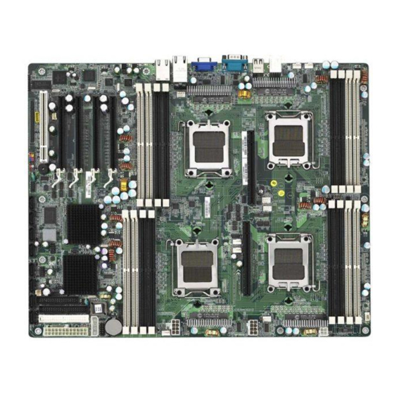
Page 8: Board Image
2.1- Board Image This picture is representative of the latest board revision available at the time of publishing. The board you receive may or may not look exactly like the above picture. -
Page 9: Block Diagram
2.2 - Block Diagram Thunder n4250QE S4985G3NR Block Diagram... -
Page 10: Board Parts, Jumpers And Connectors
2.3 - Board Parts, Jumpers and Connectors This diagram is representative of the latest board revision available at the time of publishing. The board you receive may not look exactly like the above diagram. - Page 11 Jumper Legend ©© OPEN - Jumper OFF, without jumper cover ©© CLOSED – Jumper ON, with jumper cover Jumper/Connector Function SMBUS Connector Fan Connector (for barebone use only) Clear CMOS Jumper - Pin 2-3 closed: Normal (Default) - Pin 1-2 closed: Clear NMI Header USB Front Panel Headers J30/J95...
- Page 12 J122 J14: FAN Connector (for barebone use only) Use these pin definitions to connect to the barebone fans. Signal Signal CPUFAN0_TACH CPUFAN2_TACH CPUFAN1_TACH CPUFAN3_TACH SYSFAN0_TACH CPU_FAN_TACH2 SYSFAN4_TACH SYSFAN5_TACH CPUFAN0_PWM...
- Page 13 JP1: RI Header Use this header to connect to the external device of wake on ring. JP2: Intruder Header Use this header to connect to the device for intruder function . J22: NMI Header Use this header to issue a non-maskable interrupt.
- Page 14 J115 J101 J115: Front Panel Header The Front Panel Header is used to connect some control or signal wires from motherboard to chassis, such as HDD LED, power LED, power button, and reset button. ¾2 HDDLED+ 1¾ PWR LED+ ¾4 HDDLED- 3¾...
- Page 15 Reconnect power supply to AC source Clear Power on system J101: COM2 Header Use these pin definitions to connect a port to COM2. *TYAN does not provide cable for this header. It is designed for OEM use only. Signal Signal J30/J95: USB Front Panel Headers...
- Page 16 SYSFAN4 SYSFAN1 SYSFAN3 SYSFAN0 SYSFAN5 SYSFAN2 SYSFAN6 SYSFAN7 SATA 0/1/2/3/4/5/6/7...
- Page 17 CPUFAN0/CPUFAN1/CPUFAN2/CPUFAN3: CPU Fan Connectors G ND Use this header to connect the processor cooling fan to your motherboard to keep the system at Tac homet er optimum performance levels. P WM SYSFAN0/SYSFAN1/SYSFAN2/SYSFAN3/SYSFAN4/SYSFAN5: Chassis Fan Connectors G ND Use this header to connect the chassis cooling fan to your motherboard to keep the system at Tac homet er optimum performance levels.
-
Page 18: Tips On Installing Motherboard In Chassis
Some chassis’ include plastic studs instead of metal. Although the plastic studs are usable, TYAN recommends using metal studs with screws that will fasten the motherboard more securely in place. Below is a chart detailing what the most common motherboard studs look... -
Page 19: Installing The Processor(S)
2.5 - Installing the Processor(s) & Heatsink(s) Your Thunder n4250QE S4985G3NR supports the latest processor technologies from AMD. Check the TYAN website for latest processor support: http://www.tyan.com... - Page 20 Processor Installation The processor should be installed carefully. Make sure you are wearing an antistatic strap and handle the processor as little as possible. Follow these instructions to install your processor: Place the PCB such that the socket cam side faces you. Make sure the lever hook is on your top-left side.
- Page 21 Remove the PnP cap. Use your left hand to hold the load plate. Then use your right thumb to remove the PnP cap from the load plate. With the package in the socket, the PnP cap removal process will not damage the contacts.
- Page 22 Heatsink Installation While installing the heatsink, be careful in mounting the heatsink into the chassis to enhance the support of shock and vibration acting on the heatsink. Do not mount the heatsink into the back plate only to prevent excessive pressure on the PCB that will cause serious damage to processor socket and mainboard.
-
Page 23: Installing The Memory
Before installing memory, ensure that the memory you have is compatible with the motherboard and processor. Only DDR2-667/533/400 DIMM modules are required. Check the TYAN Web site at: www.tyan.com for details of the type of memory recommended for your motherboard. - Page 24 Memory Installation Procedure Follow these instructions to install memory modules into the Thunder n4250QE S4985G3NR. Press the locking levers in the direction shown in the following illustration. Align the memory module with the socket. The memory module is keyed to fit only one way in the socket. Key slot Seat the module firmly into the socket by gently pressing down until it sits flush with the socket.
-
Page 25: Attaching Drive Cables
Attaching IDE Drive Cable Attaching the IDE drive cable is simple. These cables are “keyed” to only allow them to be connected in the correct manner. TYAN motherboards have two on-board IDE channels, each supporting two drives. The black connector designates the Primary channel, while the white connector designates the Secondary channel. - Page 26 Tyan has supplied two SATA cables and one SATA power adapter. If you are in need of other cables or power adapters please contact your place of purchase. The following pictures illustrate how to connect an SATA drive 1. SATA drive cable connection 2.
-
Page 27: Installing Add-In Cards
2.8 - Installing Add-In Cards Before installing add-in cards, it’s helpful to know if they are fully compatible with your motherboard. For this reason, we’ve provided the diagrams below, showing the slots that appear on your motherboard. PC I (3 2- bit 33MHz) PC I Expr es s (x1 6) PC I Expr es s (x4 ) Simply find the appropriate slot for your add-in card and insert the card... -
Page 28: Connecting External Devices
2.9 - Connecting External Devices The following diagrams will detail the rear port stack for this S4985 motherboard: 1. PS/2 Mouse & Keyboard 2. USB x2 3. Serial Port 4. VGA Port 5. RJ-45 LAN Port 6. RJ-45 LAN Port 7. -
Page 29: Installing The Power Supply
2.10 - Installing the Power Supply There are five power connectors on your Thunder n4250QE S4985G3NR. The Thunder n4250QE S4985G3NR requires that you have an EPS12V power supply that has a 24-pin and two 8-pin power connectors. Except the 24-pin and 8-pin power supplies, you also need to connect the two 4-pin power supply for the power of processor if you want to use Quad Rand memory. -
Page 30: Finishing Up
2.11 - Finishing up Congratulations on making it this far! You’re finished setting up the hardware aspect of your computer. Before closing up your chassis, make sure that all cables and wires are connected properly, especially IDE cables and most importantly, jumpers. You may have difficulty powering on your system if the motherboard jumpers are not set correctly. -
Page 31: Chapter 3: Bios Setup
Chapter 3: BIOS Setup 3.1. About the BIOS The BIOS is the basic input/output system, the firmware on the motherboard that enables your hardware to interface with your software. The BIOS determines what a computer can do without accessing programs from a disk. The BIOS contains all the code required to control the keyboard, display screen, disk drives, serial communications, and a number of miscellaneous functions. - Page 32 Chipset section unless you are absolutely sure of what you are doing. The Chipset defaults have been carefully chosen either by TYAN or your system manufacturer for best performance and reliability. Even a seemingly small change to the Chipset setup options may cause the system to become unstable or unusable.
-
Page 33: Bios Main Menu
3.2 BIOS Main Menu In this section, you can alter general features such as the date and time, as well as access to the IDE configuration options. Note that the options listed below are for options that can directly be changed within the Main Setup screen. PhoenixBIOS Setup Utility Main Advanced... - Page 34 This allows the BIOS to run full diagnostic tests to detect any problems that may slip past Quick Boot's abbreviated testing scheme. After a few error-free test runs, you should enable this feature for much faster booting. Enabled / Disabled Boot-time Diagnostic Screen This feature is used to display the diagnostic screen during the boot process.
-
Page 35: Advanced Menu
3.3 Advanced Menu This section facilitates configuring advanced BIOS options for your system. PhoenixBIOS Setup Utility Main Advanced Memory Security Boot Power Exit Item Specific Help [Win2K/KP] Installed O/S: Secured Setup Configurations [No] [No] Reset Configuration Data: Hammer Configuration Integrated Devices FirstWare Configuration PCI Configuration IDE Configuration... - Page 36 This BIOS feature allows you to manually force the BIOS to clear the previously saved ESCD data and reconfigure the settings. All you need to do is enable this BIOS feature and then reboot your computer. The new ESCD should resolve the conflict and allow the operating system to load normally.
- Page 37 3.3.1 Hammer Configuration PhoenixBIOS Setup Utility Main Advanced Memory Security Boot Power Exit Hammer Configuration Item Specific Help ECC Options [Enabled] SW Mem Hole Remap: [Auto] DRAM Bank Interleave [Disabled] Node Interleave [Enabled] ACPI SRAT Table [Disabled] Online Spare [Enabled] Auto DOS Training [Auto] Set FID to MaxFID...
- Page 38 Auto DQS Training [Disabled]: Do DQS training on every cold boot. [Enabled]: Train DQS only when the installed DIMMs are changed. Enabled / Disabled Set FID to MaxFID Enable this option to set the FID to MaxFID on fused, non-server parts. It also sets the VID to 50mV less than the MaxFID.
- Page 39 3.3.1.1 ECC Options Sub-Menu PhoenixBIOS Setup Utility Main Advanced Memory Security Boot Power Exit ECC Options Sub Menu Item Specific Help ECC Mode [Disabled] [Disabled] ECC Error Checking [Disabled] ECC Error Log [Disabled] DCache ECC Scrub Control [Disabled] L2 ECC Scrub Control [Disabled] DRAM ECC Scrub Control [Disabled]...
- Page 40 L2 ECC Scrub Control Set the rate of background scrubbing for the L2 cache. Enabled / Disabled DRAM ECC Scrub Control Set the rate of background scrubbing for DRAM. Enabled / Disabled ECC Scrub Redirection This feature is used to enable ECC scrubber to correct errors detected in DRAM during normal CPU requests.
- Page 41 3.3.2 Integrated Devices PhoenixBIOS Setup Utility Main Advanced Memory Security Boot Power Exit Integrated Devices Item Specific Help USB Control [Enabled] [Enabled] USB BIOS Legacy Support: [Enabled] MAC LAN: [Enabled] MAC LAN Bridge: MAC Address: [Disabled] SATA0 Controller: [Disabled] SATA1 Controller: [APIC] Interrupt Mode: Slave Devices Configuration...
- Page 42 SATA0/1 Controller This option allows you to configure First Serial ATA Device on CK804 NOTE: Mobile platform, please enable SATA, SAVE and EXIT BIOS SETUP. Then, you must do a power cycle during next POST. Disabled/ Enabled Interrupt Mode This option allows you to select interrupt mode between 8259/PIC mode or APIC mode.
- Page 43 3.3.2.1 Slave Devices Configuration Sub-Menu PhoenixBIOS Setup Utility Main Advanced Memory Security Boot Power Exit Slave Devices Configuration Item Specific Help MAC LAN: [Enabled] [Enabled] MAC LAN Bridge: MAC Address: [Disabled] SATA0 Controller: [Disabled] SATA1 Controller: ↑↓ Help Select Item Change Values Setup Defaults ←...
- Page 44 3.3.2.2 NV RAID Configuration Sub-Menu PhoenixBIOS Setup Utility Main Advanced Memory Security Boot Power Exit NV RAID Configuration Item Specific Help NV RAID Configuration: [Disabled] [Disabled] IDE Primary Master [Disabled] IDE Primary Slave [Disabled] IDE Secondary Master [Disabled] IDE Secondary Slave [Disabled] Master SATA0 Primary [Disabled]...
- Page 45 3.3.3 FirstWare Configuration PhoenixBIOS Setup Utility Main Advanced Memory Security Boot Power Exit FirstWare Configuration Item Specific Help FirstWare Language: [English] FirstWare Authentication Level [High] FirstWare Video Mode [800x600] ↑↓ Help Select Item Change Values Setup Defaults ← → u Sub-Menu Exit Select Menu Enter...
-
Page 46: Pci Configuration
3.3.4 PCI Configuration This screen contains the additional setup menu to configure PCI devices. PhoenixBIOS Setup Utility Main Advanced Memory Security Boot Power Exit PCI Configuration Item Specific Help PCI Device, Slot #1 [Enabled] Onboard VGA [Add on] Default Primary Video Adapter: PCI/PNP ISA UHB Region Exclusion PCI/PNP ISA IRQ Region Exclusion ↑↓... - Page 47 3.3.4.1 PCI Device, Slot#1 Sub-Menu This screen contains the setup items for configuring the specific PCI device. PhoenixBIOS Setup Utility Main Advanced Memory Security Boot Power Exit PCI Device, Slot#1 Item Specific Help [Enabled] Option ROM Scan: [Enabled] Enable Master: [0040h] Latency Timer: ↑↓...
- Page 48 3.3.4.2 PCI/PNP ISA UHB Region Exclusion Sub-Menu You can use this screen to select options for the PCI/PNP ISA UHB Region Exclusion settings. Use the up and down <Arrow> keys to select an item. Use the <Plus> and <Minus> keys to change the value of the selected option. PhoenixBIOS Setup Utility Main Advanced...
- Page 49 3.3.4.3 PCI/PNP ISA IRQ Resource Exclusion Sub-Menu You can use this screen to select options for the PCI/PNP IRQ Resource Exclusion settings. Use the up and down <Arrow> keys to select an item. Use the <Plus> and <Minus> keys to change the value of the selected option. PhoenixBIOS Setup Utility Main Advanced...
- Page 50 3.3.5 IDE Configuration This section allows you to fine tune the IDE configuration. PhoenixBIOS Setup Utility Main Advanced Memory Security Boot Power Exit IDE Configuration Item Specific Help HDD Detect [Enabled] [DOS] Large Disk Access Mode: [Both] Local Bus IDE adapter Primary Master Primary Slave Secondary Master...
- Page 51 3.3.5.1 Primary Master/Slave, Secondary Master/Slave Sub-Menu Computer detects IDE drive type from drive C to drive F. Press Enter on any of the Primary/Master, Primary/Slave, Secondary/Master, Secondary/Slave options to view advanced details of the corresponding drive. The system displays advanced details like the number of heads/cylinders/sectors on the detected disk and the maximum storage capacity of the disk.
- Page 52 LBA Mode Control Enables or disables LBA Mode. When LBA is turned on, the BIOS will enable geometry translation. This translation may be done in the same way that it is done in Extended CHS or large mode, or it may be done using a different algorithm called LBA-assist translation.
-
Page 53: Floppy Configuration
3.3.6 Floppy Configuration You can use this screen to select options for the Floppy Configuration settings. Use the up and down <Arrow> keys to select an item. Use the <Plus> and <Minus> keys to change the value of the selected option. PhoenixBIOS Setup Utility Main Advanced... - Page 54 3.3.7 I/O Device Configuration This setting allows you to configure I/O devices. PhoenixBIOS Setup Utility Main Advanced Memory Security Boot Power Exit I/O Device Configuration Item Specific Help Serial port A: [Enabled] [3F8] Base I/O address: [IRQ4] Interrupt: [Enabled] Serial port B: [Normal] Mode: [2F8]...
- Page 55 Base I/O Address This sets the base I/O address for serial port B. 2F8 / 3F8 / 3E8 / 2E8 Interrupt This sets the interrupt for serial port B. IRQ3 / IRQ4 Parallel port: This defines how the parallel port is detected and configured. Auto / Disable / Enabled Mode This feature is used to set the mode for parallel port.
-
Page 56: Hardware Monitor
3.3.8 Hardware Monitor This displays critical system parameters like CPU speed, fan speeds, voltage levels and CPU temperature. PhoenixBIOS Setup Utility Main Advanced Memory Security Boot Power Exit Hardwar Monitor Item Specific Help CPU0 Temperature CPU1 Temperature CPU2 Temperature CPU3 Temperature Sys1 Temperature Sys2 Temperature Sys3 Temperature... -
Page 57: Console Redirection
3.3.9 Console Redirection PhoenixBIOS Setup Utility Main Advanced Memory Security Boot Power Exit Console Redirection Item Specific Help Com Port Address [Disabled] [19.2K] Baud Rate [PC ANSI] Console Type [CTS/RTS] Flow Control [Direct] Console connection: [Off] Continue C.R. after POST: ↑↓... - Page 58 3.3.10 Watchdog Timer option PhoenixBIOS Setup Utility Main Advanced Memory Security Boot Power Exit Watchdog Timer option Item Specific Help Watchdog Timer [Disabled] Timer_out Minutes ↑↓ Select Item Help Change Values F9 Setup Defaults ← → Select Menu u Sub-Menu Esc Exit Enter Select F10 Previous Values...
- Page 59 3.4 Memory This setting allows you to tweak the various cache settings for optimal performance of your system. Press Enter to display the various cache settings. PhoenixBIOS Setup Utility Main Advanced Memory Security Boot Power Exit Item Specific Help Cache Ram System Memory: [xxxx KB] Extended Memory:...
- Page 60 any program writes into this memory area, it will result in a system crash. So, it is recommended that you write protect this area for optimal system performance. Uncached / Write Back Cache Video BIOS Area This feature is only valid when the video BIOS is shadowed. It enables or disables the caching of the video BIOS ROM at C0000h-C7FFFh via the L2 cache.
- Page 61 3.5 Security These settings allow you to configure the security options for your system. PhoenixBIOS Setup Utility Main Advanced Memory Security Boot Power Exit Item Specific Help Supervisor Password Is: User Password Is: Set Supervisor Password Set User Password [Disabled] Password on boot: [Normal] Fixed disk boot sector:...
- Page 62 3.6 Boot Menu Use this screen to select options for the Boot Settings Configuration. PhoenixBIOS Setup Utility Main Advanced Memory Security Boot Power Exit Item Specific Help [Enabled] POST Error: Boot priority order: Excluded from boot order: ↑↓ Help Select Item Change Values Setup Defaults u Sub-Menu...
-
Page 63: Power Menu
3.8 Power Menu These settings allow you to configure the power options for your system. PhoenixBIOS Setup Utility Main Advanced Memory Security Boot Power Exit Item Specific Help [Yes] Enable ACPI: [Disabled] AMD PowerNow [Disabled] C State Configuration [Disabled] CPU Throttle [Off] Resume On Time [00:00:00]... - Page 64 Resume Time This allows you to set RTC wakeup time. Hour:Minute:Second Resume Date This allows you to set RTC wakeup Date. Month:Day:Century Power Button Off This allows you to let Power button possibly shutdown the system in legacy OS without holding for 4 seconds Enabled / Disable Spread Spectrum When enabled, this option modulates the frequency of the CPU clock rate (and...
-
Page 65: Exit Menu
3.7 Exit Menu These settings set the exit options on your system. PhoenixBIOS Setup Utility Main Advanced Security Power Boot Exit Item Specific Help Exit Saving Changes Exit system Setup and Exit Discarding Changes save your changes to CMOS. Load Setup Defaults Discard Changes Save Changes ↑↓... - Page 66 NOTE...
-
Page 67: Chapter 4: Diagnostics
The most common type of error is a memory error. Before contacting your vendor or TYAN Technical Support, be sure that you note as much as you can about the beep code length and order that you experience. Also, be ready with information regarding add-in cards, drives and O/S to speed the support process and come to a quicker solution. -
Page 68: Bios Post Code
4.3 - BIOS Post Code Code Beeps / Description Code Beeps / Description Verify Real Mode Test CPU bus-clock frequency Disable Non-Maskable Initialize Phoenix Dispatch Interrupt (NMI) Manager Get CPU type Warm start shut down Initialize system hardware Shadow system BIOS ROM Initialize chipset with initial Autosize cache POST values... - Page 69 system BIOS shadow caches 1-4-1-1. RAM failure on Setup System Management data bits of high byte of Mode (SMM) area memory bus Display external L2 cache Check key lock size Load custom defaults Initialize Typematic rate (optional) Display shadow-area Erase F2 prompt message Display possible high Scan for F2 key stroke...
- Page 70 Fixup Multi Processor table BIOS Boot Block 1-2. Search for option BIOS Boot Block ROMs. Check for SMART Drive Initialize the CPU (optional) Shadow option ROMs Initialize system timer Set up Power Management Initialize system I/O Initialize security engine Check force recovery boot (optional) Enable hardware interrupts Checksum BIOS ROM...
-
Page 71: Appendix I: Smdc Information
It enables any IT Manager by providing multi-interfaces to access the hardware remotely and perform monitor, control and diagnose activities effectively. Tyan SMDC is not a peripheral card. Unlike regular peripheral card such as AGP card, Network card or SCSI card, SMDC does not require any hardware specific driver. - Page 72 Features of Tyan Server Management Monitor various system components remotely - such as fans, processor temperature, and more Remote power on and power off Console redirect -the ability to view system remotely Alert and error actions -such as audible beep, e-mail, power down and reboot...
-
Page 73: Appendix Ii: How To Make A Driver Diskette
Appendix II: How to Make a Driver Diskette Follow the steps below to make a driver diskette from the TYAN driver CD provided. Start the system and insert the TYAN CD into the CD-ROM drive to boot from CD. You will see the following menu. Then press [1] and [Enter] to boot the system to Tyan diskette maker. - Page 74 Follow the instruction on menu to insert a diskette and press [ENTER]. Please insert a formatted diskette into A:/ and press [ENTER] Writing image to drive A: Track: 36 Hoad: 8 Sector: 1 Using "ESC" key to quit the Tyan diskette maker. The system will automatically restart.
-
Page 75: Glossary
Glossary ACPI (Advanced Configuration and Power Interface): a power management specification that allows the operating system to control the amount of power distributed to the computer’s devices. Devices not in use can be turned off, reducing unnecessary power expenditure. AGP (Accelerated Graphics Port): a PCI-based interface which was designed specifically for demands of 3D graphics applications. - Page 76 Bus: a data pathway. The term is used especially to refer to the connection between the processor and system memory, and between the processor and PCI or ISA local buses. Bus mastering: allows peripheral devices and IDEs to access the system memory without going through the CPU (similar to DMA channels).
- Page 77 EEPROM (Electrically Erasable Programmable ROM): also called Flash BIOS, is a ROM chip which can, unlike normal ROM, be updated. This allows you to keep up with changes in the BIOS programs without having to buy a new chip. TYAN’s BIOS updates can be found at http://www.tyan.com EMRL: Embedded RAID Logic.
- Page 78 IDE (Integrated Device/Drive Electronics): a simple, self-contained HDD interface. It can handle drives up to 8.4 GB in size. Almost all IDEs sold now are in fact Enhanced IDEs (EIDEs), with maximum capacity determined by the hardware controller. IDE INT (IDE Interrupt): a hardware interrupt signal that goes to the IDE. I/O (Input/Output): the connection between your computer and another piece of hardware (mouse, keyboard, etc.) Initial Program Load (IPL): a feature built into BBS-compliant devices, describing...
- Page 79 PCI-to-PCI bridge: allows you to connect multiple PCI devices onto one PCI slot. Pipeline burst SRAM: a type of RAM that can maintain it’s data as long as power is provided to the memory chips. In this configuration, SRAM requests are pipelined, which means that larger packets of data are sent to the memory at one time, and acted upon quickly.
- Page 80 RAM (Random Access Memory): technically refers to a type of memory where any byte can be accessed without touching the adjacent data, is often used to refer to the system’s main memory. This memory is available to any program running on the computer.
- Page 81 UltraDMA-33/66/100: a fast version of the old DMA channel. UltraDMA is also called UltraATA. Without proper UltraDMA controller, your system cannot take advantage of higher data transfer rates of the new UltraDMA/UltraATA hard drives. USB (Universal Serial Bus): a versatile port. This one port type can function as a serial, parallel, mouse, keyboard or joystick port.
-
Page 82: Technical Support
Return Merchandise Authorization (RMA) number. The RMA number should be prominently displayed on the outside of the shipping carton and the package should be mailed prepaid. TYAN will pay to have the board shipped back to you. - Page 83 Notice for the USA Compliance Information Statement (Declaration of Conformity Procedure) DoC FCC Part 15: This device complies with part 15 of the FCC Rules Operation is subject to the following conditions: This device may not cause harmful interference, and This device must accept any interference received including interference that may cause undesired operation.
Need help?
Do you have a question about the Thunder n4250QE-S4985G3NR-E and is the answer not in the manual?
Questions and answers