Table of Contents
Advertisement
///
Thunder n3600M
S2932
Version 1.1
Copyright
Copyright © TYAN Computer Corporation, 2007. All rights reserved. No part of
this manual may be reproduced or translated without prior written consent from
TYAN Computer Corp.
Trademark
All registered and unregistered trademarks and company names contained in
this manual are property of their respective owners including, but not limited to
the following.
TYAN, Thunder n3600M are trademarks of TYAN Computer Corporation.
AMD, Opteron, and combinations thereof are trademarks of AMD Corporation.
AMI, AMI BIOS are trademarks of AMI Technologies.
Microsoft, Windows are trademarks of Microsoft Corporation.
®
Marvell
is a trademark of Broadcom Corporation and/or its subsidiaries.
nVIDIA, nForce are trademarks of NVIDIA Corporation.
Notice
Information contained in this document is furnished by TYAN Computer
Corporation and has been reviewed for accuracy and reliability prior to printing.
TYAN assumes no liability whatsoever, and disclaims any express or implied
warranty, relating to sale and/or use of TYAN products including liability or
warranties relating to fitness for a particular purpose or merchantability. TYAN
retains the right to make changes to product descriptions and/or specifications
at any time, without notice. In no event will TYAN be held liable for any direct or
indirect, incidental or consequential damage, loss of use, loss of data or other
malady resulting from errors or inaccuracies of information contained in this
document.
1
Advertisement
Table of Contents

Related Manuals for TYAN Thunder n3600M (S2932


Summary of Contents for TYAN Thunder n3600M (S2932
- Page 1 In no event will TYAN be held liable for any direct or indirect, incidental or consequential damage, loss of use, loss of data or other malady resulting from errors or inaccuracies of information contained in this document.
-
Page 2: Table Of Contents
Table of Contents Check the box contents! Page 3 Chapter 1: Introduction Congratulations Page 5 Hardware Specifications Page 5 Chapter 2: Board Installation Board Image Page 8 Block Diagram Page 9 Board Parts, Jumpers and Connectors Page 10 Installing the Processor Page 22 Tips on Installing Motherboard in Chassis Page 27... -
Page 3: Check The Box Contents
1 x Thunder n3600M Quick 1 x Thunder n3600M Quick Reference guide Reference guide 1 x TYAN driver CD 1 x TYAN driver CD 1 x I/O shield 1 x I/O shield 1 x SLI bridge 1 x SLI bridge... - Page 4 NOTE...
-
Page 5: Chapter 1: Introduction Congratulations
CAD, Graphics Design, and High Bandwidth Video Editing, etc. Remember to visit TYAN’s Website at http://www.TYAN.com. There you can find information on all of TYAN’s products with FAQs, online manuals and BIOS upgrades. 1.2 - Hardware Specifications... - Page 6 • Temperature and voltage •IEEE802.3 compliant, WOL/PXE monitoring support • Watchdog timer • Port 80 code display LED BIOS • TYAN IPMI support •AMI BIOS 8Mbit Flash •Supports ACPI 2.0 Memory •PnP, DMI2.0, WfM2.0 power • Dual memory channels management •...
-
Page 7: Chapter 2: Board Installation
Unplug the power from your computer power supply and then touch a safely grounded object to release static charge (i.e. power supply case). For the safest conditions, TYAN recommends wearing a static safety wrist strap. (2) Hold the motherboard by its edges and do not touch the bottom of the board, or flex the board in any way. -
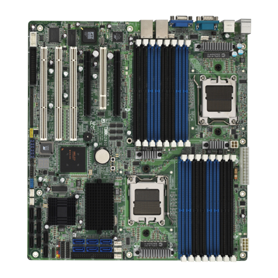
Page 8: Board Image
2.1- Board Image This picture is representative of the latest board revision available at the time of publishing. The board you receive may or may not look exactly like the above picture. -
Page 9: Block Diagram
2.2 - Block Diagram SDRAM DDR2 SDRAM DDR2 SDRAM DDR2 SDRAM DDR2 SDRAM DDR2 SDRAM DDR2 SDRAM DDR2 SDRAM DDR2 slot SDRAM DDR2 SDRAM DDR2 slot PCI-X SDRAM DDR2 DDR2SDRAM SDRAM DDR2 slot PCI-X SDRAM DDR2 SDRAM DDR2 slot PCI-X SDRAM DDR2 Thunder n3600M S2932 Block Diagram... -
Page 10: Board Parts, Jumpers And Connectors
2.3 - Board Parts, Jumpers and Connectors SMSC C OM1 SC H5017 U SB 1 U SB 1 LA N1 LAN2 Ma rve ll 88E 112 1 F AN 5 CP UFAN2 KB/ MS 32 MB E S1000 E S1000 D DR CPU2 J 17... - Page 11 Floppy Connector SMDC Connector IPMB Pin Header PW1/PW2/PW3 Power Connectors (see p.34 for details) LCM Pin Header (for Barebone use only) TYAN Front Panel 2 Connector (for Barebone use J39/J63 only) Front Panel USB2.0 Connectors Primary IDE Connector Front Panel Header...
- Page 13 I2C1DA GND5 I2C4CLK I2C4DA GND6 I2C3CLK The SMDC connector allows you to I2C3DA 5VSB1 I2C2CLK I2C2DA connect with Tyan Server Management 5VSB2 GND7 PWRBTN# PCIPME# Daughter Card (SMDC). The S2932 RSTBTN# COM_TXD OEMBTN# COM_RXD supports Tyan SMDC M3291. See EXTSMI#...
- Page 14 JP1/JP2/JP3/JP4/JP5/JP6 (from top to bottom) JP1/JP2: PCI-S1/PCI-S2 Speed Setting Jumper Max frequency is 133MHz Max frequency is 100MHz...
- Page 15 JP3/JP4: SMDC Select Jumper Support SMDC. Please note that both JP3 and JP4 must be Pin #2-3 closed to support SMDC. JP5: VGA Enable/Disable Jumper Enable the onboard VGA function. (Default) Disable the onboard VGA function. JP6: SAS Enable/Disable Jumper Enable the onboard SAS function.
- Page 16 J41: Front Panel USB2.0 Connector Signal Signal USB PWR USB PWR USB1- USB2- USB1+ USB2+ Use these headers to connect to the USB devices via the enclosed USB cable.
- Page 17 J8: COM Port Pin Header Use these pin definitions to connect a port to COM2. *TYAN does not provide cable for this header. It is designed for OEM use only. Signal Signal J39: TYAN Front Panel 2 Connector (for Barebone use only)
- Page 19 J38: LCM Pin Header (for Barebone use only) Signal Signal VCC5V RXD2 5VSB TXD2 this header to connect the LCM module with system monitoring function. This header is reserved for barebone use. J65: SGPIO Header (for Barebone use only) Signal Signal SDATA_OUT0 SDATA_IN0...
- Page 20 SAS1 SAS0 SAS3 SAS2 SAS6 SAS4 SAS7 SAS5 Top: from left to right SATA0, SATA2, SATA4 Bottom: from left to right SATA1, SATA3, SATA5...
- Page 21 J7/J42/J43/J59/J62: Front Fan Connectors J59/J62 Use these headers to connect the chassis cooling fans to your motherboard to keep Tach omete r +1 2V the system stable and reliable. PW M J59: FAN1, J62: FAN2, J42: FAN3, J43: Tachomet er + 12 V FAN4 J7: FAN5...
-
Page 22: Installing The Processor
2.4 - Installing the Processor Your Thunder n3600M S2932 supports the latest processor technologies from AMD. Check the TYAN website for latest processor support: http://www.tyan.com Exploded View of AMD PIB Platforms Thermal Solution based on AMD Socket F Processor... - Page 23 Back plate Assembly The back plate is mounted on the backside of the motherboard and enhances local stiffness to support shock and vibration loads acting on the heat sink. The back plate assembly prevents excessive motherboard warpage in the area near the processor.
- Page 24 Locate four screw holes on socket and screw the socket to the PCB board. NOTE: Do not assemble CPU before securing socket with screws. Inspect Socket F assembly to PCB. The Socket F must be tightly attached onto the PCB. There must NOT be any gap between stand off the PCB.
- Page 25 Processor Installation The processor should be installed carefully. Make sure you are wearing an antistatic strap and handle the processor as little as possible. Follow these instructions to install your processor: Place the PCB such that the socket cam side faces you. Make sure the lever hook is on your top-left side.
- Page 26 Remove the PnP cap. Use your left hand to hold the load plate. Then use your right thumb to remove the PnP cap from the load plate. With the package in the socket, the PnP cap removal process will not damage the contacts.
-
Page 27: Tips On Installing Motherboard In Chassis
Some chassis’ include plastic studs instead of metal. Although the plastic studs are usable, TYAN recommends using metal studs with screws that will fasten the motherboard more securely in place. Below is a chart detailing what the most common motherboard studs look... -
Page 28: Installing The Memory
Before installing memory, ensure that the memory you have is compatible with the motherboard and processor. Only DDR2 register ECC/non-ECC memory modules are required. Check the TYAN Web site at www.tyan.com for details of the type of memory recommended for your motherboard. - Page 29 Memory Installation Procedure Follow these instructions to install memory modules into the Thunder n3600M. Press the locking levers in the direction shown in the following illustration. Align the memory module with the socket. The memory module is keyed to fit only one way in the socket. Key slot Seat the module firmly into the socket by gently pressing down until it sits flush with the socket.
-
Page 30: Attaching Drive Cables
Connections for these drives are very simple. There is no need to set Master/Slave jumpers on SATA drives. Tyan has supplied two SATA cables and one SATA power adapter. If you are in need of other cables or power adapters please contact your place of... - Page 31 The following pictures illustrate how to connect an SATA drive 1. SATA drive cable connection 2. SATA drive power connection 3. SATA cable motherboard connector 4. SATA drive power adapter Attaching Floppy Drive Cables Attaching floppy diskette drives are done in a similar manner to hard drives. See the picture below for an example of a floppy cable.
-
Page 32: Installing Add-In Cards
2.8 - Installing Add-in Cards Before installing add-in cards, it’s helpful to know if they are fully compatible with your motherboard. For this reason, we’ve provided the diagrams below, showing the most common slots that may appear on your motherboard. Not all of the slots shown will necessarily appear on your motherboard. -
Page 33: Connecting External Devices
2.9 - Connecting External Devices Your motherboard supports a number of different interfaces through connecting peripherals. See the following diagrams for the details. PS/2 Mouse/Keyboard 10/100/1000 10/100/1000 LAN2 Port LAN1 Port USB x 2 Serial Port VGAPort NOTE: Peripheral devices can be plugged straight into any of these ports but software may be required to complete the installation. -
Page 34: Installing The Power Supply
2.10 - Installing the Power Supply There are three power connectors on your Thunder n3600M S2932. The Thunder n3600M S2932 requires that you have an EPS12V power supply that has a 24-pin, an 8-pin and a 4-pin power connectors. NOTE: Please be aware that ATX 2.x, ATX12V and ATXGES power supplies may not be compatible with the board and can damage the motherboard and/or CPU(s). -
Page 35: Finishing Up
2.11 – Finishing up Congratulations on making it this far! You’re finished setting up the hardware aspect of your computer. Before closing up your chassis, make sure that all cables and wires are connected properly, especially IDE cables and most importantly, jumpers. You may have difficulty powering on your system if the motherboard jumpers are not set correctly. - Page 36 NOTE...
-
Page 37: Chapter 3: Bios Setup
Chapter 3: BIOS Setup 3.1 About the BIOS The BIOS is the basic input/output system, the firmware on the motherboard that enables your hardware to interface with your software. The BIOS determines what a computer can do without accessing programs from a disk. The BIOS contains all the code required to control the keyboard, display screen, disk drives, serial communications, and a number of miscellaneous functions. -
Page 38: Setup Basics
Chipset section unless you are absolutely sure of what you are doing. The Chipset defaults have been carefully chosen either by TYAN or your system manufacturer for best performance and reliability. Even a seemingly small change to the Chipset setup options may cause the system to become unstable or unusable. -
Page 39: Bios Main Menu
3.6 BIOS Main Menu The Main BIOS Menu is the first screen that you can navigate. The Main BIOS setup menu screen has two main frames. The left frame displays all the options that can be configured. "Grayed-out" options cannot be configured, options in blue can be changed. -
Page 40: Advanced Menu
3.7 Advanced Menu You can select any of the items in the left frame of the screen, such as Super I/O Configuration, to go to the sub menu for that item. You can display an Advanced BIOS Setup option by highlighting it using the <Arrow> keys. All Advanced BIOS Setup options are described in this section. -
Page 41: Cpu Configuration
Feature Option Description Advanced Settings USB Configuration Menu Item Configure the USB support Configure AMD PowerNow AMD PowerNow Configuration Menu Item support Onboard Devices Menu Item Configure onboard devices Configuration 3.7.1 CPU Configuration You can use this screen to view CPU Configuration Menu. Use the up and down arrow ( / ) keys to select an item. - Page 42 Feature Option Description CPU Configuration Module Version AGESA Version Read only Displays information about CPU Physical Count Logical Count Revision Cache L1 Cache L2 Cache L3 Read only Displays information about CPU Speed Current FSB Multiplier Maximum FSB Multiplier Able to change Freq. uCode Patch Level This option should remain disabled Disabled...
- Page 43 3.7.2 IDE Configuration Sub-Menu You can use this screen to select options for the IDE Configuration Settings. Use the up and down <Arrow> keys to select an item. Use the <Plus> and <Minus> keys to change the value of the selected option. BIOS Setup Utility Main Advanced...
- Page 44 3.7.2.1 nVidia RAID Setup BIOS Setup Utility Main Advanced PCI/PnP Boot Security Chipset Exit While entering setup, RAID Setup BIOS auto detects the presence of IDE devices. This displays nVidia RAID Function [Disabled] the status of auto detection of IDE devices.
- Page 45 3.7.2.2 Primary IDE Master/Slave Sub-Menu BIOS Setup Utility Main Advanced PCI/PnP Boot Security Chipset Exit Primary IDE Master Selects the type of device connected to the Device: Not Detected system. ← → Select Screen Type [Auto] ↑↓ Select Item LBA /Large Mode [Auto] Change Option Block (Multi-Sector Transfer)
- Page 46 3.7.2.3 SATA0/1/2/3/4/5 Sub-Menu BIOS Setup Utility Main Advanced PCI/PnP Boot Security Chipset Exit SATA0 ← → Select Screen Device: Not Detected ↑↓ Select Item Change Option Tab Select Field LBA /Large Mode [Auto] General Help Block (Multi-Sector Transfer) [Auto] F10 Save and Exit PIO Mode [Auto] ESC Exit...
- Page 47 3.7.3 Floppy Configuration Sub-Menu You can use this screen to specify options for the Floppy Configuration Settings. Use the up and down <Arrow> keys to select an item. Use the <Plus> and <Minus> keys to change the value of the selected option. The settings are described on the following pages.
- Page 48 3.7.4 Super IO Configuration Sub-Menu You can use this screen to select options for the Super I/O settings. Use the up and down arrow ( / ) keys to select an item. Use the Plus and Minus (+/-) keys to change the value of the selected option BIOS Setup Utility Main Advanced...
- Page 49 3.7.5 ACPI Configuration Sub-Menu Use this screen to select options for ACPI. Use the up and down arrow ( / ) keys to select an item. Use the Plus and Minus (+/-) keys to change the value of the selected option. A description of the selected item appears on the right side of the screen.
- Page 50 3.7.5.1 Advanced ACPI Configuration Sub-Menu BIOS Setup Utility Main Advanced PCI/PnP Boot Security Chipset Exit Advanced ACPI Configuration ← → Select Screen ACPI Version Features [ACPI v2.0] ↑↓ Select Item ACPI APIC support [Enabled] Change Option AMI OEMB table [Enabled] General Help Headless mode [Disabled]...
- Page 51 3.7.5.2 Chipset ACPI Configuration Sub-Menu BIOS Setup Utility Main Advanced PCI/PnP Boot Security Chipset Exit MCP55 ACPI HPET TABLE [Disabled] ← → Select Screen ↑↓ Select Item Change Option General Help F10 Save and Exit ESC Exit Feature Option Description Chipset ACPI Configuration Disabled ACPI High Precision Event Timer...
-
Page 52: Apm Configuration
3.7.6 APM Configuration BIOS Setup Utility Main Advanced PCI/PnP Boot Security Chipset Exit Resume On PME# [Disabled] Resume On PCIE Wake# [Disabled] ← → Select Screen Resume On LAN (MAC) [Disabled] Resume On RTC Alarm [Disabled] ↑↓ Select Item Change Option General Help Restore on AC Power Loss [Last State]... - Page 53 3.7.7 Event Log Configuration Sub-Menu You can use this screen to view the Event Log Control Menu. This logs system events (such as CMOS clear) and writes the log into NVRAM. Use the up and down arrow ( / ) keys to select an item. Use the Plus and Minus (+/-) keys to change the value of the selected option.
- Page 54 3.7.8 Hardware Health Configuration Sub-Menu You can use this screen to view the Hardware Health Configuration Settings. Use the up and down arrow ( / ) keys to select an item. Use the Plus and Minus (+/-) keys to change the value of the selected option. The settings are described on the following pages.
- Page 55 Feature Option Description Hardware Health Configuration Enabled H/W Health Function Enables Hardware Health Monitoring Device. Disabled Fan Control Mode Disabled CPUFAN1, 2 FAN1, 2 Disabled: Fan full speed PWM Control Enabled: Fan speed automatically adjusts Enabled according to specific temperature. Fan Control Mode Disabled FAN3, FAN4, FAN5...
- Page 56 3.7.8.1 Mainboard Voltages Report Sub-Menu You can use this screen to monitor mainboard’s voltages. Use the up and down arrow ( / ) keys to select an item. Use the Plus and Minus (+/-) keys to change the value of the selected option. BIOS Setup Utility Main Advanced...
- Page 57 3.7.9 Remote Access Configuration Sub-Menu You can use this screen to view the Remote Access Configuration Menu. This feature allows access to the Server remotely via serial port. Use the up and down arrow ( / ) keys to select an item. Use the Plus and Minus (+/-) keys to change the value of the selected option.
- Page 58 Feature Option Description Configure Remote Access type and parameters Disable: Turns off the redirection Disabled after POST Boot Loader: Redirection is active during POST Redirection After BIOS and during Boot Loader. Boot Loader POST Always: Redirection is always active. <Some OSs may not work if set to Always Always>...
- Page 59 3.7.10 USB Configuration Sub-Menu You can use this screen to view the USB Configuration Menu. Use the up and down arrow ( / ) keys to select an item. Use the Plus and Minus (+/-) keys to change the value of the selected option. The settings are described on the following pages.
- Page 60 3.7.11 AMD PowerNow Configuration Sub-Menu You can use this screen to view the AMD PowerNow Configuration Menu. Use the up and down arrow ( / ) keys to select an item. Use the Plus and Minus (+/-) keys to change the value of the selected option. The settings are described on the following pages.
- Page 61 3.7.12 Onboard Devices Configuration Sub-Menu You can use this screen to view the Onboard Devices Configuration Menu. Use the up and down arrow ( / ) keys to select an item. Use the Plus and Minus (+/-) keys to change the value of the selected option. The settings are described on the following pages.
-
Page 62: Pci Pnp Menu
3.8 PCI PnP Menu You can use this screen to view PnP (Plug & Play) BIOS Configuration Menu. This menu allows the user to configure how the BIOS assigns resources & resolves conflicts. Use the up and down arrow ( / ) keys to select an item. Use the Plus and Minus (+/-) keys to change the value of the selected option. - Page 63 Feature Option Description Advanced PCI/PnP Settings Clears NVRAM during system Clear NVRAM Boot. No: lets the BIOS configure all the devices in the system. Yes: lets the operating system Plug & Play OS configure Plug and Play (PnP) devices not required for boot if your system has a Plug and Play operating system.
-
Page 64: Boot Menu
3.9 Boot Menu You can display Boot Setup option by highlighting it using the Arrow ( / ) keys and pressing Enter. The settings are described on the following pages. BIOS Setup Utility Main Advanced PCI/PnP Boot Security Chipset Exit Boot Settings Configures settings during System Boot. - Page 65 Feature Option Description Boot Settings Configuration Enabled This option allows user bypass BIOS Quick Boot self test during POST. Disabled Disabled: displays normal POST Disabled messages. Quiet Boot Enabled: displays OEM log instead of Enabled POST messages. Allows user to force BIOS/Option ROM Force BIOS Add On ROM Display of add-on cards to be displayed during...
-
Page 66: Boot Device Priority
3.9.2 Boot Device Priority Use this screen to select options for the Boot Device Priority. Use the up and down arrow ( / ) keys to select an item. Use the Plus and Minus (+/-) keys to change the value of the selected option. BIOS Setup Utility Main Advanced... -
Page 67: Removable Drives
3.9.3 Removable Drives Use this screen to select options for the Removable Drives. Use the up and down arrow ( / ) keys to select an item. Use the Plus and Minus (+/-) keys to change the value of the selected option. BIOS Setup Utility Main Advanced... -
Page 68: Network Drives
3.9.4 Network Drives Use this screen to select options for the Network Drives. Use the up and down arrow ( / ) keys to select an item. Use the Plus and Minus (+/-) keys to change the value of the selected option. BIOS Setup Utility Main Advanced... -
Page 69: Security Menu
3.10 Security Menu The system can be configured so that all users must enter a password every time the system boots or when BIOS Setup is entered, using either the Supervisor password or User password. The Supervisor and User passwords activate two different levels of password security. -
Page 70: Chipset Menu
3.11 Chipset Menu This menu allows the user to customize functions of the AMD Chipsets. North Bridge configuration contains options for Memory & CPU settings. South Bridge configuration contains options for SM Bus & USB. Additional configuration for the AMD8131 PCI-X Tunnel is available in the PCI-X Configuration Menu. Select a menu by highlighting it using the Arrow ( / ) keys and pressing Enter. - Page 71 3.11.1 Northbridge Configuration Sub-Menu This menu gives options for customizing memory & Hypertransport settings. Select a menu by highlighting it using the Arrow ( / ) keys and pressing Enter. The settings are described on the following pages. BIOS Setup Utility Main Advanced PCI/PnP...
- Page 72 Feature Option Description NorthBridge Chipset Configuration It shows the clock frequency of the Memory CLK Read only installed SDRAM. This controls the timing delay (in clock CAS Latency (Tcl) Read only cycles) before SDRAM starts a read command after receiving it. When DRAM is refreshed, both rows and columns are addressed separately.
- Page 73 3.11.1.1 Memory Configuration Sub-Menu This menu has options for memory speed & latency. Use the up and down arrow ( / ) keys to select an item. Use the Plus and Minus (+/-) keys to change the value of the selected option. BIOS Setup Utility Main Advanced...
- Page 74 Enabled Enable or disable DDR power down Power Down Enable mode Disabled Channel Power Down Mode Set DDR power down mode Chip Select...
- Page 75 3.11.1.2 ECC Configuration Sub-Menu This menu allows the user to configure ECC setup for system & DRAM. Use the up and down arrow ( / ) keys to select an item. Use the Plus and Minus (+/-) keys to change the value of the selected option. BIOS Setup Utility Main Advanced...
- Page 76 Disabled 40ns 80ns 160ns 320ns 640ns 1.28us 2.56us 5.12us DRAM scrubbing corrects memory 10.2us errors so later reads are correct. 20.5us Doing this while memory is not being DRAM BG Scrub used improves performance. 41.0us Note: When AMD’s node interleave 81.9us feature is enabled, BIOS will force 163.8us...
- Page 77 Disabled 40ns 80ns 160ns 320ns 640ns 1.28us Allows the L2/L3 Data Cache RAM to be corrected while idle. 2.56us L2 /L3 Cache BG Scrub 5.12us 10.2us 20.5us 41.0us 81.9us 163.8us 327.7us 655.4us...
- Page 78 3.11.1.3 DRAM Timing Configuration Sub-Menu This menu allows the user to configure DRAM Timing. Use the up and down arrow ( / ) keys to select an item. Use the Plus and Minus (+/-) keys to change the value of the selected option. BIOS Setup Utility Main Advanced...
- Page 79 3.11.1.4 IOMMU Option Sub-Menu This menu has options for IOMMU. Use the up and down arrow ( / ) keys to select an item. Use the Plus and Minus (+/-) keys to change the value of the selected option. BIOS Setup Utility Main Advanced PCI/PnP...
-
Page 80: Exit Menu
3.12 Exit Menu You can display an Exit BIOS Setup option by highlighting it Arrow ( / ) keys and pressing Enter. BIOS Setup Utility Main Advanced PCI/PnP Boot Security Chipset Exit Exit system setup after Exit Options saving the changes. F10 key can be used for Save Changes and Exit this operation. -
Page 81: Chapter 4: Diagnostics
BIOS flash failure, you must contact your dealer for a replacement BIOS. There are no exceptions. TYAN does not have a policy for replacing BIOS chips directly with end users. In no event will TYAN be held responsible for damages... -
Page 82: Amibios Post Code
4.3 AMIBIOS Post Code The POST code checkpoints are the largest set of checkpoints during the BIOS pre-boot process. The following table describes the type of checkpoints that may occur during the POST portion of the BIOS: Checkpoint Description Disable NMI, Parity, video for EGA, and DMA controllers. Initialize BIOS, POST, Runtime data area. - Page 83 Checkpoint Description Initializes different devices through DIM. See DIM Code Checkpoints section of document for more information. Initializes DMAC-1 & DMAC-2. Initialize RTC date/time. Test for total memory installed in the system. Also, Check for DEL or ESC keys to limit memory test. Display total memory in the system. Mid POST initialization of chipset registers.
- Page 84 NOTE...
-
Page 85: Appendix: Smdc Information
Tyan SMDC is not a peripheral card. Unlike regular peripheral card such as AGP card, Network card or SCSI card, SMDC does not require any hardware specific driver. As long as a standby power comes into the system, SMDC will begin looking after the system. - Page 86 Features of Tyan Server Management Monitor various system components remotely - such as fans, processor temperature, and more Remote power on and power off Console redirect -the ability to view system remotely Alert and error actions -such as audible beep, e-mail, power down and reboot...
-
Page 87: Glossary
Glossary ACPI (Advanced Configuration and Power Interface): a power management specification that allows the operating system to control the amount of power distributed to the computer’s devices. Devices not in use can be turned off, reducing unnecessary power expenditure. AGP (Accelerated Graphics Port): a PCI-based interface which was designed specifically for demands of 3D graphics applications. - Page 88 Bus: a data pathway. The term is used especially to refer to the connection between the processor and system memory, and between the processor and PCI or ISA local buses. Bus mastering: allows peripheral devices and IDEs to access the system memory without going through the CPU (similar to DMA channels).
- Page 89 BIOS, it is a ROM chip which can, unlike normal ROM, be updated. This allows you to keep up with changes in the BIOS programs without having to buy a new chip. TYAN’s BIOS updates can be found at http://www.tyan.com ESCD (Extended System Configuration Data): a format for storing information about Plug-n-Play devices in the system BIOS.
- Page 90 up your system. Plug-n-Play operating systems can take care of these details for you. Latency: the amount of time that one part of a system spends waiting for another part to catch up. This occurs most commonly when the system sends data out to a peripheral device and has to wait for the peripheral to spread (peripherals tend to be slower than onboard system components).
- Page 91 level 1 is known as mirroring, which stores the data within at least two hard drives, but does not stripe. RAID level 1 also allows for faster access time and fault-tolerance, since either hard drive can be read at the same time. RAID level 0+1 is both striping and mirroring, providing fault-tolerance, striping, and faster access all at the same time.
- Page 92 USB (Universal Serial Bus): a versatile port. This one port type can function as a serial, parallel, mouse, keyboard or joystick port. It is fast enough to support video transfer, and is capable of supporting up to 127 daisy-chained peripheral devices. VGA (Video Graphics Array): the PC video display standard V-SYNC: controls the vertical scanning properties of the monitor.
-
Page 93: Technical Support
Return Merchandise Authorization (RMA) number. The RMA number should be prominently displayed on the outside of the shipping carton and the package should be mailed prepaid. TYAN will pay to have the board shipped back to you. - Page 94 Notice for the USA Compliance Information Statement (Declaration of Conformity Procedure) DoC FCC Part 15: This device complies with part 15 of the FCC Rules Operation is subject to the following conditions: This device may not cause harmful interference, and This device must accept any interference received including interference that may cause undesired operation.
Need help?
Do you have a question about the Thunder n3600M (S2932 and is the answer not in the manual?
Questions and answers