Table of Contents
Advertisement
Quick Links
///
Thunder n6650W
S2915-E
Version 1.0
Copyright
Copyright © TYAN Computer Corporation, 2006. All rights reserved. No part of
this manual may be reproduced or translated without prior written consent from
TYAN Computer Corp.
Trademark
All registered and unregistered trademarks and company names contained in
this manual are property of their respective owners including, but not limited to
the following.
TYAN, Taro and Thunder n6650W are trademarks of TYAN Computer
Corporation.
AMD, Opteron, and combinations thereof are trademarks of AMD Corporation.
Nvidia and nForce are trademarks of Nvidia Corporation
Microsoft, Windows are trademarks of Microsoft Corporation.
SuSE is a trademark of Novell, Inc.
Linux is a trademark of Linus Torvalds
IBM, PC, AT, and PS/2 are trademarks of IBM Corporation.
Winbond is a trademark of Winbond Electronics Corporation.
Notice
Information contained in this document is furnished by TYAN Computer
Corporation and has been reviewed for accuracy and reliability prior to printing.
TYAN assumes no liability whatsoever, and disclaims any express or implied
warranty, relating to sale and/or use of TYAN products including liability or
warranties relating to fitness for a particular purpose or merchantability. TYAN
retains the right to make changes to product descriptions and/or specifications
at any time, without notice. In no event will TYAN be held liable for any direct or
indirect, incidental or consequential damage, loss of use, loss of data or other
malady resulting from errors or inaccuracies of information contained in this
document.
1
http://www.tyan.com
Advertisement
Table of Contents

Subscribe to Our Youtube Channel
Related Manuals for TYAN Thunder n6650W S2915-E


Summary of Contents for TYAN Thunder n6650W S2915-E
- Page 1 In no event will TYAN be held liable for any direct or indirect, incidental or consequential damage, loss of use, loss of data or other malady resulting from errors or inaccuracies of information contained in this document.
-
Page 2: Table Of Contents
Page 59 Power Menu Page 60 Exit Menu Page 61 Chapter 4: Diagnostics Flash Utility Page 63 Phoenix BIOS Post Code Page 64 Appendix I: How to Make a Driver Diskette Page 67 Glossary Page 69 Technical Support Page 75 http://www.tyan.com... - Page 3 1 x IEEE1394 cable 1 x Thunder n6650W User’s Manual 1 x Thunder n6650W Quick Reference Guide 1 x TYAN driver CD 1 x I/O shield If any of these items are missing, please contact your vendor/dealer for replacement before continuing with the installation process.
- Page 4 NOTE http://www.tyan.com...
-
Page 5: Chapter 1: Introduction Congratulations
HPC/clustering environments or workstation platforms. Remember to visit TYAN’s website at http://www.tyan.com. There you can find information on all of TYAN’s products with FAQs, online manuals and BIOS upgrades. 1.2 - Hardware Specifications... - Page 6 • Multiple boot options connectors • 48-bit LBA support • 2 stacked USB 2.0 (2) + RJ-45 (1) connectors Regulatory • Stacked Line-in, Line-out, Mic-in audio • FCC Class B (DoC) connectors • European Community CE (DoC) • SPDIF-out http://www.tyan.com...
-
Page 7: Chapter 2: Board Installation
Unplug the power from your computer power supply and then touch a safely grounded object to release static charge (i.e. power supply case). For the safest conditions, TYAN recommends wearing a static safety wrist strap. (2) Hold the motherboard by its edges and do not touch the bottom of the board, or flex the board in any way. -
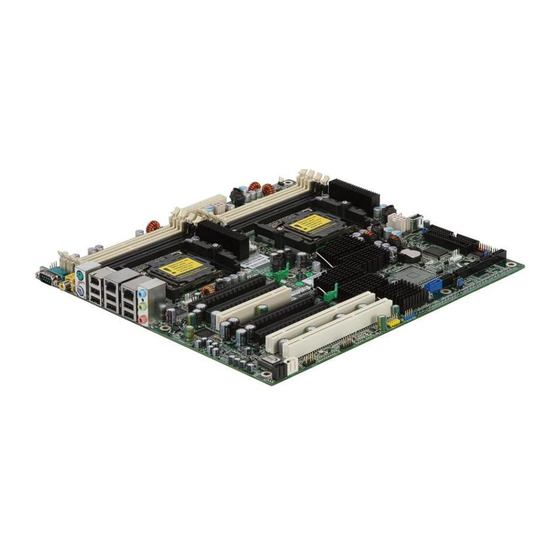
Page 8: Board Image
This picture is representative of the latest board revision available at the time of publishing. The board you receive may or may not look exactly like the above picture. The following page includes details on the vital components of this motherboard. http://www.tyan.com... -
Page 9: Block Diagram
2.2 - Block Diagram Thunder n6650W (S2915A2NRF-E) Block Diagram http://www.tyan.com... - Page 10 Thunder n6650W (S2915WA2NRF-E) Block Diagram http://www.tyan.com...
-
Page 11: Board Parts, Jumpers And Connectors
This diagram is representative of the latest board revision available at the time of publishing. The board you receive may not look exactly like the above diagram. Jumper Legend OPEN - Jumper OFF, without jumper covered CLOSED – Jumper ON, with jumper covered http://www.tyan.com... - Page 12 1394 Pin Header High Definition Audio Header Chassis Intrusion Header USB Pin Header USB Pin Header CD_IN Connector AUX_IN Connector SPDIF_IN Connector 1394 Disable Jumper JP29 SAS Disable Jumper JP13 PCI-X Speed Select Jumper Clear CMOS Jumper Front Panel Header http://www.tyan.com...
- Page 13 CPUFAN1 SYSFAN0 CPUFAN0 SYSFAN2 SYSFAN1 SYSFAN3 SYSFAN4 SYSFAN5 http://www.tyan.com...
- Page 14 Use these headers to connect cooling fans to the Ta ch omete r motherboard to keep the system stable and +12V reliable. CPUFAN1 CPUFAN0 & CPUFAN1 Pin 1 Pin 2 Pin 3 Pin 4 +12V Tachometer +1 2V Tac ho me ter http://www.tyan.com...
- Page 15 http://www.tyan.com...
- Page 16 P24: USB Pin Header Use this header to connect to front panel USB connector. Signal Signal USB DATA- USB DATA- USB DATA+ USB DATA+ P26: USB Pin Header Use this header to connect to a USB connector. Signal USB DATA- USB DATA+ http://www.tyan.com...
- Page 17 http://www.tyan.com...
- Page 18 HDD LED- Power LED- Power S/W+ The motherboard Reset SW+ provides one front panel header for electrical connection to the front panel switches and 5VSB LED’s. INTRU# J12: 1394 Pin Header Signal Signal TPA+ TPA- TPB+ TPB- +12V +12V http://www.tyan.com...
- Page 19 JP29 JP13 http://www.tyan.com...
- Page 20 The CMOS will be cleared when the screen is on. Finally shut down the power, replace E50 to the default setting (1-2), power on the system again. (Default) J61: 1394 Disable Jumper Open: Enable 1394 functionality (Default) Closed: Disable 1394 functionality http://www.tyan.com...
-
Page 21: Tips On Installing Motherboard In Chassis
Some chassis’ include plastic studs instead of metal. Although the plastic studs are usable, TYAN recommends using metal studs with screws that will fasten the motherboard more securely in place. Below is a chart detailing what the most common motherboard studs look like and how they should be installed. -
Page 22: Installing The Processor(S)
2.5 - Installing the Processor(s) Your S2915 supports the latest processor technologies from AMD. Check the TYAN website for latest processor support: http://www.tyan.com Figure 1. Detailed View of the Thermal Solution AMD PIB Platforms based on the AMD Socket F Processor... - Page 23 PCB. The remaining four shorter PEM nuts should automatically fit the 4 holes on the PCB as shown in the following pictures. 4 PEM nuts Let 2 upper & should fit 4 lower-middle holes. PEM nuts pass through the holes. http://www.tyan.com...
- Page 24 Locate four screw holes on socket and screw the socket to the PCB board. NOTE: Do not assemble CPU before securing socket with screws. Inspect Socket F assembly to PCB. The Socket F must be tightly attached onto the PCB. There must NOT be any gap between stand off the PCB. http://www.tyan.com...
-
Page 25: Installing The Memory
Before installing memory, ensure that the memory you have is compatible with the motherboard and processor. Only DDR2- 400/533/667 DIMM modules are required. Check the TYAN Web site at: www.tyan.com for details of the type of memory recommended for your motherboard. - Page 26 Align the memory module with the socket. The memory module is keyed to fit only one way in the socket. Key slot Seat the module firmly into the socket by gently pressing down until it sits flush with the socket. The locking levers pop up into place. http://www.tyan.com...
- Page 27 Refer to the following table for supported DDR2 populations. (Note: X indicates a populated DIMM slot) Single CPU Installed Dual CPU installed (CPU0 only) (CPU0 and CPU1) Population Option CPU0 DIMM0 CPU0 DIMM1 CPU0 DIMM2 CPU0 DIMM3 CPU1 DIMM0 CPU1 DIMM1 CPU1 DIMM2 CPU1 DIMM3 http://www.tyan.com...
-
Page 28: Attaching Drive Cables
Attaching Serial ATA Cables The Thunder n6650W is also equipped with 4 Serial ATA (SATA) channels. Connections for these drives are also very simple. There is no need to set Master/Slave jumpers on SATA drives. http://www.tyan.com... - Page 29 In most cases, there will be a key pin on the cable which will force a proper connection of the cable. http://www.tyan.com...
- Page 30 Attach first floppy drive (drive A:) to the end of the cable with the twist in it. Drive B: is usually connected to the next possible connector on the cable (the second or third connector after you install Drive A:). http://www.tyan.com...
-
Page 31: Installing Add-In Cards
It is better to try another slot or return the faulty card rather than damaging both the motherboard and the add-in card. YOU MUST ALWAYS unplug the power connector from the motherboard before performing system hardware NOTE changes. Otherwise you may damage the board and/or expansion device. http://www.tyan.com... -
Page 32: Connecting External Devices
The chart below illustrates the different LED states. Description Left LED Right LED No Link Link 10Mbps GREEN Rig h t L e ft Activity 10Mbps GREEN(blink) Green Linked at 100Mbps Green Green Activity 100Mbps Green(blink) Green(blink) Linked at 1000Mbps Green Activity 1000Mbps Green(blink) http://www.tyan.com... -
Page 33: Installing The Power Supply
Connect the EPS 12V 24-pin power connector. Connect the EPS 12V 4-pin power connector. Connect power cable to power supply and power outlet. YOU MUST unplug the power supply from the wall outlet before NOTE plugging the power cables to motherboard connectors. http://www.tyan.com... -
Page 34: Finishing Up
In the rare circumstance that you have experienced difficulty, you can find help by asking your vendor for assistance. If they are not available for assistance, please find setup information and documentation online at our website or by calling your vendor’s support line. http://www.tyan.com... - Page 35 NOTE http://www.tyan.com...
-
Page 36: Chapter 3: Bios
The table below shows how to use the setup program with the keyboard. Function Moves from one selection to the next Left/Right Arrow Keys Changes from one menu to the next Up/Down Arrow Keys Moves between selections Enter Opens highlighted section PgUp/PgDn Keys Changes settings. http://www.tyan.com... - Page 37 The best advice is to only alter settings that you thoroughly understand. In particular, do not change settings in the Chipset section unless you are sure of the outcome. TYAN or your system manufacturer has carefully chosen the chipset defaults for best performance and reliability. Even a seemingly small change to the Chipset setup options may cause the system to become unstable or unusable.
-
Page 38: Main Bios Setup
Use this menu to configure security settings for your system. Boot Use this menu to configure boot options for your system. Power Use this menu to specify your settings for power management. Exit This contains the various BIOS exit options. http://www.tyan.com... - Page 39 This allows the system to skip certain tests while booting. This will decrease the time needed to boot the system. Options: Enabled / Disabled QuietBoot Mode This displays the diagnostic screen during boot. Options: Enabled / Disabled Summary Screen This displays system configuration on boot. Options: Enabled / Disabled http://www.tyan.com...
- Page 40 This displays the amount of cache memory present on the system. System Time / Date setup System Time: Adjusts the system clock. HHHours (24hr. format): MMMinutes : SSSeconds System Date: Adjusts the system date. MMMonths : DDDays : YYYYYears http://www.tyan.com...
- Page 41 Select [Yes] if you want to clear the ESCD area. Options: Yes / No LPC Port 80 This item allows you to enable or disable the LPC Port 80. Disable to use the PCI port 80 card. Options: Enabled / Disabled http://www.tyan.com...
- Page 42 Enable the DRAM controller to designate a DIMM bank as a spare for logical swap during runtime. Options: Disabled / Enabled Auto DQS Training [Disabled]: Do DQS training on every cold boot. [Enabled]: Train DQS only when the installed DIMMs are changed. Options: Enabled / Disabled http://www.tyan.com...
- Page 43 Sets the rate of background scrubbing for the L2 cache. Options: Disabled / Enabled ECC Error Log Enable the MCA to log or report ECC errors on the DRAM bus. NOTE: The MCA must still be programmed according to the desired MCE outcome. http://www.tyan.com...
- Page 44 IOMMU is supported on Linux based systems to convert 32bit PCI IO addresses to 64bits. Options: Disabled / Enabled IOMMU Size It allows you to select the IOMMU size. Options: 32 MB / 64 MB / 128 MB / 256 MB / 512 MB / 1 GB / 2 GB http://www.tyan.com...
- Page 45 Options: Enabled / Disabled MAC LAN Bridge Enable MAC LAN Bridge. Options: Enabled / Disabled MAC 1 LAN Enable/disable MAC 1 LAN device. Options: Enabled / Disabled MAC 1 LAN Bridge Enable MAC 1 LAN Bridge. Options: Enabled / Disabled http://www.tyan.com...
- Page 46 Secondary SATA Channel. Both options are listed in Integrated Devices. Options: Disabled / Enabled SATA1, port 2 / SATA1, port 3 / SATA0, port 0 / SATA0, port 1 / Master SATA2 Primary / Master SATA2 Secondary Enable this device as RAID. Options: Disabled / Enabled http://www.tyan.com...
- Page 47 Korean / Chinese (T) FirstWare authentication Level Selects FirstWare authentication level. Options: High / Medium / Low FirstWare Video Mode Selects FirstWare Video Mode. Options: 640 x 480 / 800 x 600 / 1024 x 768 / 1280 x 1024 http://www.tyan.com...
- Page 48 3.4.4 PCI Configuration Press [Enter] to enter each sub-menu for configuration. 3.4.4.1 PCI Device, Slot #1 Sub-Menu Option ROM Scan Initializes device expansion ROM. Options: Disabled / Enabled http://www.tyan.com...
- Page 49 Minimum guaranteed time slice allotted for bus master in units of PCI bus clocks. Options: Default / 0020h / 0040h / 0060h / 0080h / 00A0h / 00C0h / 00E0h 3.4.4.2 Integrated SAS Controller Sub-Menu Integrated SAS Enable the integrated SAS controller. Options: Disabled / Enabled http://www.tyan.com...
- Page 50 Enables/Disables the integrated 1394 controller. Options: Disabled / Enabled 3.4.4.4 PCI/PNP ISA UMB Region Exclusion Sub-Menu C800-CBFF / CC00-CFFF / D000-D3FF/ D400-D7FF / D800-DBFF / DC00-DFFF Reserves the specified block of upper memory for use by legacy ISA devices. Options: Reserved / Available http://www.tyan.com...
- Page 51 3.4.4.5 PCI/PNP ISA IRQ Resource Exclusion Sub-Menu IRQ 3/4/5/7/9/10/11/15 Reserves the specified IRQ for use by legacy ISA devices. Options: Reserved / Available http://www.tyan.com...
- Page 52 Different operating systems require different representations of drive geometries. Options: Other / DOS Local Bus IDE Adapter Enable the integrated local bus IDE adapter. Options: Primary / Secondary http://www.tyan.com...
- Page 53 Int 13h calls. The difference between LBA and ECHS is that when using ECHS the BIOS translates the parameters used by these calls from the translated geometry to http://www.tyan.com...
- Page 54 DMA protocols, it can be added to many existing computers by installing an Ultra DMA/33 Peripheral Component Interconnect adapter card. Ultra DMA uses the same 40-pin Integrated Drive Electronics interface cable as PIO and DMA. Options: Disabled / Mode 0 / Mode 1 / Mode 2 / Mode 5 http://www.tyan.com...
- Page 55 This section allows you to select the Floppy Configuration. Legacy Diskette A Selects floppy type. Options: NONE / 360 KB, 5.25 in / 1.2 MB, 5.25 in / 720 KB, 3.5 in / 1.44/1.25 MB, 3.5 in / 2.88 MB, 3.5 in http://www.tyan.com...
- Page 56 Options: Enabled / Disabled / Auto / OS Controlled Base I/O Address Set the base I/O address for Serial Port A. Options: 3E8 / 2E8 / 2F8 / 3F8 Interrupt Set the Interrupt for Serial Port A. Options: IRQ3 / IRQ4 http://www.tyan.com...
- Page 57 Console Connection It indicates whether the console is connected directly to the system or a modem is used to connect. Options: Direct / via Modem Continue C.R. After POST Enables Console Redirection after OS has loaded. Options: Off / On http://www.tyan.com...
- Page 58 Setting this to [Yes] will clear the DMI event log after rebooting. Options: Yes / No Event Logging Select [Enabled] to allow logging of DMI events. Options: Enabled / Disabled Mark DMI Events as Read Press [Enter] to mark all DMI events in the event log as read. http://www.tyan.com...
- Page 59 It displays reminder message at boot (daily, every Monday or 1 of every month). Options: Disabled / Enabled System Backup Reminder It displays reminder message at boot (daily, every Monday or 1 of every month). Options: Disabled / Enabled http://www.tyan.com...
- Page 60 3.6 Boot Use this screen to configure the boot priority order. Boot Priority Order It shows the boot priority for installed devices. Excluded from boot order It lists devices to be excluded from boot order. http://www.tyan.com...
- Page 61 Sets the mode of operation if an AC/Power Loss occurs. The two modes are: [Enabled]: restores the previous power state before loss occurred. [Disabled]: keeps the power off until the power button is pressed. Options: Power On / Stay Off / Last State http://www.tyan.com...
- Page 62 This exits BIOS setup after discarding the changes made. Load Setup Defaults This loads the factory default values. Discard Changes This discards all changes made without exiting BIOS setup. Save Changes This saves all changes made without exiting BIOS setup. http://www.tyan.com...
- Page 63 NOTE http://www.tyan.com...
-
Page 64: Chapter 4: Diagnostics
BIOS flash failure, you must contact your dealer for a replacement BIOS. There are no exceptions. TYAN does not have a policy for replacing BIOS chips directly with end users. In no event will TYAN be held responsible for damages done by the end user. -
Page 65: Phoenix Bios Post Code
640 KB Autosize DRAM Test extended memory Initialize POST Memory Test extended memory Manager address lines Clear 512 KB base RAM Jump to UserPatch1 1-3-4-1. RAM failure on Configure advanced cache address registers 1-3-4-3. RAM failure on Initialize Multi Processor http://www.tyan.com... - Page 66 Initialize floppy controller Initialize error display function Determine number of ATA Initialize system error drives (optional) handler Initialize hard-disk PnPnd dual CMOS controllers (optional) Initialize local-bus hard-disk Initialize notebook docking controllers (optional) Jump to UserPatch2 Initialize notebook docking http://www.tyan.com...
- Page 67 Initialize PIC and DMA Initialize System Management Mode Initialize Memory type Output one beep before boot Initialize Memory size Boot to Mini DOS Shadow Boot Block Clear Huge Segment System memory test Boot to Full DOS Initialize interrupt vectors http://www.tyan.com...
-
Page 68: Appendix I: How To Make A Driver Diskette
Appendix I: How to Make a Driver Diskette Follow the steps below to make a driver diskette from the TYAN driver CD provided. Start the system and insert the TYAN CD into the CD-ROM drive to boot from CD. You will see the following menu. Then press [1] and [Enter] to boot the system to TYAN diskette maker. - Page 69 Follow the instruction on menu to insert a diskette and press [ENTER]. Please insert a formatted diskette into A:/ and press [ENTER] Writing image to drive A: Track: 36 Hoad: 8 Sector: 1 Using "ESC" key to quit the TYAN diskette maker. The system will automatically restart. http://www.tyan.com...
-
Page 70: Glossary
The CPU can manipulate data in a buffer before copying it to a disk drive. While this improves system performance (reading to or writing from a disk drive a single time is much faster than doing so repeatedly) there is the possibility of http://www.tyan.com... - Page 71 CPU. This frees up CPU resources for other tasks. As with IRQs, it is vital that you do not double up devices on a single line. Plug-n-Play devices will take care of this for you. http://www.tyan.com...
- Page 72 BIOS, it is a ROM chip which can, unlike normal ROM, be updated. This allows you to keep up with changes in the BIOS programs without having to buy a new chip. TYAN’s BIOS updates can be found at http://www.tyan.com ESCD (Extended System Configuration Data): a format for storing information about Plug-n-Play devices in the system BIOS.
- Page 73 PnP (Plug-n-Play): a design standard that has become ascendant in the industry. Plug-n-Play devices require little set-up to use. Devices and operating systems that are not Plug-n-Play require you to reconfigure your system each time you add or change any part of your hardware. http://www.tyan.com...
- Page 74 AcceleRAID 150, 200 or 250, to implement RAID on a system board-embedded SCSI bus or a set of SCSI busses. SISL: SCSI Interrupt Steering Logic ( LSI ) (only on LSI SCSI boards) Sleep/Suspend mode: in this mode, all devices except the CPU shut down. http://www.tyan.com...
- Page 75 CPUs without damaging the sensitive CPU pins. The CPU is lightly placed in an open ZIF socket, and a lever is pulled down. This shifts the processor over and down, guiding it into the board and locking it into place. http://www.tyan.com...
-
Page 76: Technical Support
(which can have expensive consequences). If these options are not available for you then Tyan Computer Corporation can help. Besides designing innovative and quality products for over a decade, Tyan has continuously offered customers service beyond their expectations. - Page 77 Authorization (RMA) number. The RMA number should be prominently displayed on the outside of the shipping carton and the package should be mailed prepaid. TYAN will pay to have the board shipped back to you. Notice for the USA Compliance Information Statement (Declaration of...
Need help?
Do you have a question about the Thunder n6650W S2915-E and is the answer not in the manual?
Questions and answers