Table of Contents
Advertisement
Quick Links
Advertisement
Table of Contents

Related Manuals for Commell LV-683


Summary of Contents for Commell LV-683
- Page 1 LV-683 Mini-ITX Miniboard User’s Manual Edition 1.1 2012/01/09...
- Page 2 LV-683 User’s Manual Copyright Copyright 2011. All rights reserved. This document is copyrighted and all rights are reserved. The information in this document is subject to change without prior notice to make improvements to the products. This document contains proprietary information and protected by copyright. No part of this document may be reproduced, copied, or translated in any form or any means without prior written permission of the manufacturer.
-
Page 3: Oaldc
LV-683 User’s Manual Packing List: Please check the package content before you starting using the board. Hardware: LV-683 Mini-ITX motherboard x 1 Cable Kit: SATA Cable x 2 (OALSATA-L) DC Power Cable x 1 (OALDC-2) (OSCREW-8) * 2 ATX Power Output Cable x 1 (OALATX-P3S2) COM port &... - Page 4 LV-683 User’s Manual Index Chapter 1 <Introduction> ..............6 1.1 <Product Overview>....................6 1.2 <Product Specification> ..................7 1.3 <Mechanical Drawing> ..................9 1.4 <Block Diagram> ....................10 Chapter 2 <Hardware Setup> ............. 11 2.1 <Connector Location> ..................11 2.2 <Jumper Reference>....................12 2.3 <Connector Reference> ..................13 2.3.1 <Internal Connector>...
- Page 5 LV-683 User’s Manual 2.16 <Indicator and Switch>..................35 Chapter 3 <BIOS Setup> ............... 37 Appendix A <I/O Port Pin Assignment> ......39 A.1 <SATA Port>......................39 A.2 <IrDA Port> ......................39 A.3 <SMBUS Port>....................39 A.4<LPT Port> ......................40 A.5 < CRT Port >.......................40 A.6 <Serial Port>.......................41 A.7 <LAN Port>...
- Page 6 LV-683 User’s Manual (This page is left for blank)
-
Page 7: Chapter 1
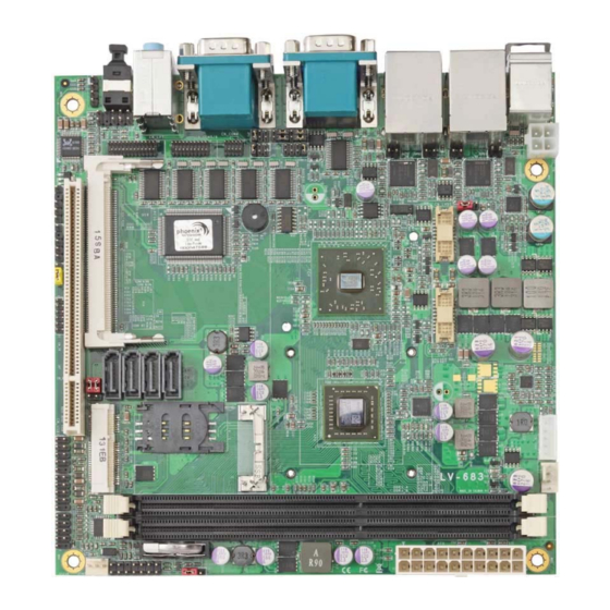
Chapter 1 <Introduction> 1.1 <Product Overview> LV-683 is the Mini-ITX motherboard with AMD G-T56N platform, with onboard VGA, Realtek ALC888 HD Codec audio, Giga LAN interface. Based on the AMD G-T56N Processor, the board provides many advanced features for reduced power consumption. -
Page 8: Product Specification
LV-683 User’s Manual 1.2 <Product Specification> General Specification Form Factor Mini-ITX motherboard AMD G-T56N Processor 1.65GHz Memory 2 x 240-pin DDR3 1066/1333MHz SDRAM up to 8GB Unbufferred, none-ECC memory supported only Chipset AMD A55E FCH Watchdog Timer System reset programmable watchdog timer with 1 ~ 255 sec./min. - Page 9 LV-683 User’s Manual Power and Environment Power Requirement Standard 20-pin ATX power supply or 5~24V full range DC Input Dimension 170 (L) x 170 (H) mm Temperature Operating within 0 ~ 60℃ Storage within -20 ~ 85℃ The specifications may be different as the actual production.
-
Page 10: Mechanical Drawing
LV-683 User’s Manual 1.3 <Mechanical Drawing>... -
Page 11: Block Diagram
LV-683 User’s Manual 1.4 <Block Diagram> 2 x 240-pin DDR3 1066/1333MHz up to 8GB CRT / DVI / LVDS G-T56N Processor HD Audio PCI Express mini card 10 x USB port Mini PCI & PCI 4 x SATA 2 x Giga LAN... -
Page 12: Chapter 2
LV-683 User’s Manual Chapter 2 <Hardware Setup> 2.1 <Connector Location> CN AUDIO CN_COM5/6 CN_COM4 CN_LPT DC_IN Mini PCI CN_SMBUS CN_IR CN_LVDS CN_DIO CN_DVI SATA1/2/3/4 CN_INV MINI_CARD CPUFAN DDR3_A&B CN_USB1/2 CN_LPC SYSFAN JFRNT LV-683 COM1 COM3 RJ45& USB COM2 Audio SPDIF... -
Page 13: Jumper Reference
LV-683 User’s Manual 2.2 <Jumper Reference> Jumper Function JRTC CMOS Operating/Clear Setting AT/ATX Mode Setting JCSEL1/2 COM2 RS232/422/485/IrDA Mode Setting COM3 signal mode switch (For Pin-9) COM4 signal mode switch (For Pin-9) JVUSB USB Voltage Setting JVLCD Panel Voltage Setting... -
Page 14: Connector Reference
LV-683 User’s Manual 2.3 <Connector Reference> 2.3.1 <Internal Connector> Connector Function Remark LGA1155 CPU socket DDRIIIA/B 240 –pin DDR3 SDRAM DIMM socket S_ATAII1/2/3/4/ 7-pin Serial ATA II connector 24-pin power supply connector DC_IN 4-pin +12V additional power supply connector CN_AUDIO... -
Page 15: Cpu And Memory Setup
LV-683 User’s Manual 2.4 <CPU and Memory Setup> LV-683 has two 240-pin DDR3 DIMM support up to 8GB of memory capacity. The memory frequency supports 1066/1333 MHz. Only Non-ECC memory is supported. DDR3A&B... -
Page 16: Cmos & Atx Setup
LV-683 User’s Manual 2.5 <CMOS & ATX Setup> The board’s data of CMOS can be setting in BIOS. If the board refuses to boot due to inappropriate CMOS settings, please remove battery to clear (reset) the CMOS to its default values. -
Page 17: Sata & Cfast Interface
LV-683 User’s Manual 2.6 <SATA & CFast Interface> Based on Intel A55E, the board provides Four Serial ATAII interfaces with up to 300MB/s of transfer rate. SATA1/2/3/4... -
Page 18: Lan Interface
LV-683 User’s Manual 2.8 <LAN Interface> The board integrates with two Intel 82583V Gigabit Ethernet controllers, as the PCI Express bus. The Intel 82583V supports triple speed of 10/100/1000Base-T, with IEEE802.3 compliance and Wake-On-LAN supported. LAN1 LAN2... -
Page 19: Onboard Display Interface
LV-683 User’s Manual 2.9 <Onboard Display Interface> Based on AMD G-T56N chipset with built-in AMD Radeon HD 6300 series Graphics, the board provides one DB15 connector on real external I/O port, and one 20-pin DVI and one LVDS interface with 5-pin LCD backlight inverter connector. The board provides dual display function with clone mode and extended desktop mode for CRT, DVI and LVDS. -
Page 20: Digital Display
LV-683 User’s Manual 2.9.2 <Digital Display> The board provides one 20-pin LVDS for 18 bit single channel panels, supports up to 1600 x 900 of resolution, with one LCD backlight inverter connector and one jumper for panel voltage setting CN_LVDS... - Page 21 LV-683 User’s Manual Connector: CN_INV Jumper: JVLCD Type: 5-pin Inverter power connector Type: 3-pin Power select jumper Connector model: JST B5B-XH-A Description Description +12V LVDS_VARY_BL +3.3V Default: 2-3 INV_ON Connector: CN_LVDS Type: onboard 20-pin connector for LVDS connector Connector model: HIROSE DF13-20DP-1.25V...
- Page 22 LCD Installation Guide: Preparing the LV-683, LCD panel and the backlight inverter You would need a LVDS type cable. Panel side...
- Page 23 LV-683 User’s Manual After setup the devices well, you need to select the LCD panel type in the BIOS. The panel type mapping is list below: LV-683 BIOS panel type selection form On board Single channel LVDS 18bit Output format...
-
Page 24: Dvi Interface
LV-683 User’s Manual 2.9.3 <DVI Interface > The board also comes with a DVI interface. Supports up to 1600 x 1200 (UXGA) of resolution. Connector: CN_DVI Connector type: HIROSE DF13-20DP-1.25V Pin Number Assignment Pin Number Assignment +3.3V Ground TMDSTX0N TMDSTX0P... -
Page 25: Onboard Audio Interface
LV-683 User’s Manual 2.10 <Onboard Audio Interface> The board provides the onboard high definition audio with Realtek ALC888 Connector: CN_AUDIO Type: 10-pin (2 x 5) 1.27mm x 2.54mm-pitch header Description Description MIC2_L AGND MIC2_R AVCC FRO_R MIC2_JD F_IO_SEN FRO_L LINE2_JD... -
Page 26: Usb2.0 Interface
LV-683 User’s Manual 2.11 <USB2.0 Interface> Based on AMD A55E FCH, the board provides Ten USB2.0 ports. The USB2.0 interface provides up to 480Mbps of transferring rate. Interface USB2.0 Controller A55E Transfer Rate Up to 480Mb/s Output Current 500mA CN_USB1/2/3... -
Page 27: Pcie Mini Card And Sim Interface
LV-683 User’s Manual 2.12 <PCIE Mini Card and SIM Interface> The board provides one PCIE mini card sockets and a SIM socket. MINI_CARD support 3G PCIE Mini card with SIM. MINI_CARD Connector: SIMM Type: 6-pin SIM socket Description Description SIMVCC... -
Page 28: Sim Setup
LV-683 User’s Manual 2.12.1 <SIM Setup> Step1. SIM card holder is marked by circle. Slide the cap toward OPEN direction. Step 2. Make sure that the cap is now at the OPEN position. Step 3. Flip the cap up for inserting a SIM card into. - Page 29 LV-683 User’s Manual Step 4. Insert a SIM card as shown in the photo. Be sure that the corner cut is on top and the golden pads are up. Step 5. Now, flip down the cap as shown in the photo.
-
Page 30: Gpio Interface
LV-683 User’s Manual 2.13 <GPIO Interface> The board provides a programmable 8-bit digital I/O interface; you can use this general purpose I/O port for system control like POS or KIOSK. Connector: CN_DIO Type: onboard 2 x 6-pin header, pitch=2.0mm Description... -
Page 31: Serial Port Jumper Setting
LV-683 User’s Manual 2.14 <Serial Port Jumper Setting > The board provides Six RS232 serial ports, with jumper selectable RS422/485/IrDA for COM2. Connector: COM2 Type: 10-pin (5 x 2) 1.27mm x 2.54mm-pitch header for COM2 Description Description DCD/422TX-/485- RXD/422TX+/485+ TXD/422RX+... - Page 32 LV-683 User’s Manual Jumper: JCSEL1/2 Type: 12-pin (6 x 2) & 8-pin (4 x 2) for set COM2 mode jumper RS232 RS485 RS422 IrDA JCSEL1 JCSEL2 Default: RS232 JCSEL1 JCSEL2...
-
Page 33: Power & Fan Connector
LV-683 User’s Manual 2.15 <Power & FAN Connector > 2.15.1 <Power Input> The board requires onboard 4-pin DC-input connector voltage range is from 5V to 24V, or onboard 20-pin ATX2.0, for the input current, please take a reference of the power consumption report on appendix. -
Page 34: Power Output
LV-683 User’s Manual 2.15.2 <Power Output> The board provides one 20-pin ATX connector for +5V/+12V output for powering your HDD, CDROM or other devices. Attention: When DC-IN had power supplied, the ATX become output ! Avoid DC-IN and ATX power supply input at the same time ! Connector: ATX (When DC-IN be used) Type: 20-pin ATX connector for +3.3V/+5V/+12V... -
Page 35: Fan Connector
LV-683 User’s Manual 2.15.3 <Fan Connector> Connector: CPUFAN Type: 4-pin fan wafer connector Description Description Ground +12V Fan Speed Detection Fan Control Connector: SYSFAN Type: 3-pin fan wafer connector Pin Description Description Description Ground +12V Sense CPUFAN SYSFAN... -
Page 36: Indicator And Switch
LV-683 User’s Manual 2.16 <Indicator and Switch> The JFRNT provides front control panel of the board, such as power button, reset and beeper, etc. Please check well before you connecting the cables on the chassis. Connector: JFRNT Type: onboard 14-pin (2 x 7) 2.54-pitch header... - Page 37 LV-683 User’s Manual (This Page is Left For Blank)
-
Page 38: Chapter 3
LV-683 User’s Manual Chapter 3 <BIOS Setup> The motherboard uses the Award BIOS for the system configuration. The Award BIOS in the single board computer is a customized version of the industrial standard BIOS for IBM PC AT-compatible computers. It supports Intel® x86 and compatible CPU architecture based processors and computers. - Page 39 LV-683 User’s Manual (This Page is Left for Blank)
-
Page 40: Appendix A
LV-683 User’s Manual Appendix A <I/O Port Pin Assignment> A.1 <SATA Port> Connector: SATA1/2/3/4 Type: 7-pin wafer connector GND RSATA_TXP1 RSATA_TXN1 GND RSATA_RXN1 RSATA_RXP1 GND A.2 <IrDA Port> Connector: CN_IR Type: 5-pin header for SIR Port Description IRRX Ground IRTX A.3 <SMBUS Port>... -
Page 41: A.4
LV-683 User’s Manual A.4<LPT Port> Connector: CN_LPT Type: 26-pin header for LPT Port Description -PSTB AFD- PRD0 ERR- PRD1 INIT- PRD2 SLIN- PRD3 PRD4 PRD5 PRD6 PRD7 ACK- BUSY SLCT A.5 < CRT Port > Connector: CRT Type: 15-pin D-sub female connector on rear panel... -
Page 42: A.6
LV-683 User’s Manual A.6 <Serial Port> Connector: COM1 Type: 9-pin D-sub male connector on rear panel Description Description Ground A.7 <LAN Port> Connector: RJ45 Type: RJ45 connector with LED on rear panel Description TRD0+ TRD0- TRD1+ TRD2+ TRD2- TRD1- TRD3+ TRD3- A.8 <LAN LED Port>... -
Page 43: Appendix B
LV-683 User’s Manual Appendix B <Flash BIOS> B.1 <Flash Tool> The board is based on Phoenix BIOS and can be updated easily by the BIOS auto flash tool. You can download the tool online at the address below: http://www.phoenix.com/en/home/ http://www.commell.com.tw/Support/Support_SBC.htm File name of the tool is “Pflash.exe”, it’s the utility that can write the data into the... -
Page 44: Appendix C
LV-683 User’s Manual Appendix C <System Resources> C.1 <I/O Port Address Map>... - Page 45 LV-683 User’s Manual...
-
Page 46: C.2
LV-683 User’s Manual C.2 <Memory Address Map >... - Page 47 LV-683 User’s Manual...
-
Page 48: C.3 < System Irq Resources
LV-683 User’s Manual C.3 < System IRQ Resources >... -
Page 49: Appendix D
LV-683 User’s Manual Appendix D <Programming GPIO’s> The GPIO can be programmed with the MS-DOS debug program using simple IN/OUT commands.The following lines show an example how to do this. GPIO0…..GPIO7 bit0……bit7 -o 2E 87 ;enter configuration. -o 2E 87... -
Page 50: Appendix E
LV-683 User’s Manual Appendix E <Watch Dog timer Setting > The watchdog timer makes the system auto-reset while it stops to work for a period. The integrated watchdog timer can be setup as system reset mode by program. Timeout Value Range... -
Page 51: Appendix F
1. Please choose “Device Manager” 2. You can see other devices ”Audio Device on High Definition Audio Bus” 3. Please choose “Audio Device on High Definition Audio Bus” then press Update Driver 4. Please select the file location”D:\LV-683\Audio(XP)\XP” 5. Install finish... -
Page 52: Contact Information
Taiwan Commate Computer Inc. 19F., No.94, Sec. 1, Xintai 5th Rd., Xizhi Dist., New Taipei Address City 22102, Taiwan +886-2-26963909 +886-2-26963911 Website h ttp://www.commell.com.tw E-Mail i nfo@commell.com.tw (General Information) t ech@commell.com.tw (Technical Support) Commell is our trademark of industrial PC division...
Need help?
Do you have a question about the LV-683 and is the answer not in the manual?
Questions and answers