Table of Contents
Advertisement
Quick Links
Advertisement
Table of Contents

Related Manuals for Commell LV-67E


Summary of Contents for Commell LV-67E
- Page 1 LV-67E Mini-ITX motherboard User’s Manual Edition: 1.2 2011/02/23...
- Page 2 LV-67E User’s Manual Copyright Copyright 2009. All rights reserved. This document is copyrighted and all rights are reserved. The information in this document is subject to change without prior notice to make improvements to the products. This document contains proprietary information and protected by copyright. No part of this document may be reproduced, copied, or translated in any form or any means without prior written permission of the manufacturer.
-
Page 3: Oales-Bku
LV-67E User’s Manual Packing List Please check package component before you use our products. Hardware: LV-67E Mini-ITX motherboard x 1 Cable Kit: DC Power Cable x 1 SATA Cable x 1 (OALDC-2) (OALSATA-L) (OSCREW-8) * 2 COM port & Printer Port Cable x 1... - Page 4 LV-67E User’s Manual LV-67EH/A/C Heatsink with Fan x 1 LV-67EG/9 Heatsink x 1 (OHS-67EF) (OHS-67E) Optional Cable: USB Cable x 1 Dual COM Port Cable x 1 (OALES-BKU2) (OALUSBA-3) 44-pin 44-pin 40-pin ATA33 IDE Cable x 1 (OALUDMA33-8) Other Accessories:...
- Page 5 LV-67E User’s Manual Index Chapter1 <Introduction>............8 1.1 <Product Overview> .....................8 1.2 <Product Specification> ..................9 1.3 <Block Diagram> ....................11 1.4 <Mechanical Drawing > ..................12 Chapter 2 <Hardware Setup> .........13 2.1 <Connector Location>..................13 2.2 <Jumper Reference> ..................15 2.3 <Connector Reference>..................16 2.3.1 <Internal Connectors>............16 2.3.2 <External Connectors>............16...
- Page 6 LV-67E User’s Manual Chapter 3 <System Configuration> .........40 3.1 <Audio Configuration> ..................40 3.2 <Video Memory Setup> ..................41 3.3 <Display Properties Setting>................43 Chapter 4 <BIOS Setup> ..........46 Appendix A <I/O Port Pin Assignment> ......48 A.1 < IDE Port >......................48 A.2 < Serial ATA Port >....................48 A.3 <...
- Page 7 LV-67E User’s Manual (This Page is Left for Blank...
-
Page 8: Product Overview
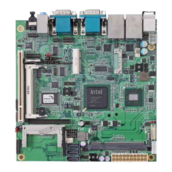
LV-67E User’s Manual Chapter1 <Introduction> 1.1 <Product Overview> LV-67EG/A/H/C/9 is the Mini-ITX motherboard with Intel® Atom™ N450/D410/D510/D525 /N455 Processor, integrated GMA3150 graphics, Intel® ICH8-M, DDR2 SO-DIMM memory, Realtek HD Audio, IDE, CF, SATAII and Intel® 82583V Gigabit LAN. Intel® Atom Processor The Intel®... -
Page 9: Product Specification
LV-67E User’s Manual 1.2 <Product Specification> General Specification Form Factor Mini-ITX motherboard Intel® Atom N450 / N455 Processor 1.66GHz (LV-67EG / LV-67E9) Intel® Atom D410 / D510 Processor 1.66GHz (LV-67EH / LV-67EA) Intel® Atom D525 Processor 1.8GHz (LV-67EC) Package type: FCBGA559... - Page 10 LV-67E User’s Manual Ethernet Interface Controller 2 x Intel® 82583V Gigabit Ethernet controller Type Triple speed 10/100/1000Base-T Auto-switching Fast Ethernet Full duplex, IEEE802.3U compliant Connector Two External RJ45 connectors with LED on rear I/O panel Audio Interface Chipset Intel® ICH8M with Realtek ALC888 HD Audio...
-
Page 11: Block Diagram
LV-67E User’s Manual 1.3 <Block Diagram> DDR2 SO-DIMM 2GB/4GB/ 4GB/4GB/2GB max. Intel® Atom N450/D410/ D510/D525/N455 18bit Single Channel LVDS Compact Flash & IDE 2 x PCIE mini card socket 3 x Serial ATA II BIOS Mini-PCI Slot ICH8M 8 x USB2.0 port... -
Page 12: Mechanical Drawing
LV-67E User’s Manual 1.4 <Mechanical Drawing > Unit: inch... -
Page 13: Connector Location
LV-67E User’s Manual Chapter 2 <Hardware Setup> 2.1 <Connector Location> SYSFAN DDRII S_ATA1/2/3 CN_INV JFRNT CN_LVDS CN_USB1/2 CN DIO CN_IR Mini-PCI Mini-Card1 CN_LPT CPUFAN CN_SMBUS CN_12V CN_AUDIO CDIN CN_COM4 CN_COM5/6 Connector Reference... - Page 14 LV-67E User’s Manual Mini-Card2 Audio USB_RJ45_1/2 COM1 + CRT COM3+COM2 SPDIF...
-
Page 15: Jumper Reference
LV-67E User’s Manual 2.2 <Jumper Reference> Jumper Function JRTC CMOS Operating/Clear Setting JVLCD Panel Voltage Setting JP39 COM3 signal mode switch (For Pin-9) JP49 COM4 signal mode switch (For Pin-9) Power mode select CN_COM2 RS-232 RS422 RS485 Setting JCSEL1 JCSEL2... -
Page 16: Connector Reference
LV-67E User’s Manual 2.3 <Connector Reference> 2.3.1 <Internal Connectors> Connector Function Remark DDRIII1/2 200 -pin DDR2 SO-DIMM SDRAM slot S_ATAII1/2/3 7-pin Serial ATA II connector 44-pin primary IDE connector Compact Flash Type II socket 24-pin power supply connector CN_12V 4-pin +12V additional power supply connector... -
Page 17: Memory Setup
LV-67E User’s Manual 2.4 <Memory Setup> Non-ECC, unbuffered memory is supported only. LE-67EG/9 provides one 200-pin DDR2 SO-DIMM to support DDR2 667 memory modules support up to 2GB of capacity. Suggestion: DDR2 SO-DIMM Modules: –Raw Card A = Double-sided x 16 –Raw Card C = Single-sided x 16... -
Page 18: Cmos & Atx Setup
LV-67E User’s Manual 2.5 <CMOS & ATX Setup> The board’s data of CMOS can be setting in BIOS. If the board refuses to boot due to inappropriate CMOS settings, here is how to proceed to clear (reset) the CMOS to its default values. -
Page 19: Enhanced Ide & Cf Interface
LV-67E User’s Manual 2.6 <Enhanced IDE & CF Interface> The board supports one enhanced IDE interface for 2 ATAPI devices with ATA33. Based on embedded application, the board has one 44-pin IDE connector +5V supported for disk on module. The board also provides a Compact Flash Type II socket. -
Page 20: Serial Ata Interface
LV-67E User’s Manual 2.7<Serial ATA Interface> Based on Intel® ICH8M, the board provides Three Serial ATAII interfaces with up to 300MB/s of transfer rate. S_ATA1/2/3... -
Page 21: Network Interface
LV-67E User’s Manual 2.8 <Network Interface> The board integrates with two Intel® 82583V Gigabit Ethernet controllers, as the PCI Express bus. The Intel® 82583V supports triple speed of 10/100/1000Base-T, with IEEE802.3 compliance and Wake-On-LAN supported. LAN2 LAN1 LAN Installation... -
Page 22: Onboard Display Interface
LV-67E User’s Manual 2.9 <Onboard Display Interface> Based on Intel® Atom N450/D410/D510/D525/N455 Processor with built-in graphics, the board provides one DB15 Connector on real external I/O port, and One 20-pin LVDS interface with 5-pin LCD backlight inverter connector. The board provides dual display function with clone mode and extended desktop mode for CRT and LVDS. -
Page 23: Digital Display Interface
2.9.2 <Digital Display Interface> The board provides one 20-pin LVDS connector for 18-bit single channel panels. LV-67EG/9 supports 1280 x 800 (WUXGA) of resolution, and LV-67E/H/A/C supports 1366 x 768 (WUXGA) of resolution, with one LCD backlight inverter connector and one jumper for panel voltage setting. - Page 24 LV-67E User’s Manual Connector: CN_INV Jumper: JVLCD Type: 5-pin Inverter power connector Type: 3-pin Power select jumper Connector model: molex_53261-5pin Description Description ENABKL +3.3V Default: 2-3 +12V Connector: CN_LVDS Type: onboard 20-pin connector for LVDS connector Connector model: HIROSE DF13-20DP-1.25V...
- Page 25 LCD Installation Guide: Preparing the LV-67E, LCD panel and the backlight inverter. Please check the datasheet of the panel to see the voltage of the panel, and set the jumper JVLCD to +5V or +3.3V.
- Page 26 LV-67E User’s Manual After setup the devices well, you need to select the LCD panel type in the BIOS. The panel type mapping is list below: LV-67E BIOS panel type selection form On board Single channel LVDS 18bit Output format...
-
Page 27: Audio Interface
LV-67E User’s Manual 2.10 <Audio Interface> The board integrates onboard audio interface with REALTEK ALC888 codec, with Intel next generation of audio standard as High Definition Audio, it offers more vivid sound and other advantages than former HD audio compliance. - Page 28 LV-67E User’s Manual Connector: CN_AUDIO Type: 10-pin (2 x 5) header (pitch = 2.54mm) Description Description MIC_L Ground MIC_R LINE_OUT_R MIC Detect SENSE LINE_OUT_L Speaker Detect Connector: CDIN Type: 4-pin header (pitch = 2.54mm) Description CD – Left Ground Ground CD –...
-
Page 29: Gpio And Smbus Interface
LV-67E User’s Manual 2.11 <GPIO and SMBUS Interface> The board provides a programmable 8-bit digital I/O interface, and a SMBUS (System management bus) interface for control panel application. Connector: CN_DIO Type: onboard 2 x 6-pin header, pitch=2.0mm Description Description Ground... -
Page 30: Usb Interface
LV-67E User’s Manual 2.12 <USB Interface> LV-67E integrates eight USB2.0 ports. The specifications of USB2.0 are listed below: Interface USB2.0 Intel® ICH8-M Controller Transfer Rate Up to 480Mb/s Voltage The Intel® ICH8-M contains two Enhanced Host Controller Interface (EHCI) and five Universal Host Controller Interfaces (UHCI), it can determine whether your connected device is for USB1.1 or USB2.0, and change the transfer rate automatically. - Page 31 LV-67E User’s Manual Connector: CN_USB1/2 Type: 10-pin (5 x 2) header for USB5/6 Ports Description Description Data0- Data1- Data0+ Data1+ Ground Ground Ground CN_USB1/2...
-
Page 32: Power Supply And Fan Interface
LV-67E User’s Manual 2.13 <Power Supply and Fan Interface> 2.13.1 <Power Input> The board requires onboard 4-pin DC-input connector voltage range is from 8V to 24V, or onboard 20-pin ATX2.0, for the input current, please take a reference of the power consumption report on appendix. -
Page 33: Power Output
LV-67E User’s Manual 2.13.2 <Power Output> The board provides one 20-pin ATX connector for +5V/+12V output for powering your HDD, CDROM or other devices. Attention: When DC-IN had power supplied, the ATX become output ! Avoid DC-IN and ATX power supply input at the same time ! Connector: ATX (When DC-IN be used) Type: 20-pin ATX connector for +3.3V/+5V/+12V... -
Page 34: Fan Connector
LV-67E User’s Manual 2.13.3 <Fan connector> The board provides one 4-pin fan connectors supporting smart fan for CPU cooler and one 3-pin cooler fan connectors for system. SYSFAN CPUFAN Connector: CPUFAN Type: 4-pin fan wafer connector Description Description Ground +12V... -
Page 35: Serial Port
LV-67E User’s Manual 2.14 <Serial Port> The board supports Three RS232 serial port and one jumper selectable RS232/422/485 serial ports. The jumper JCSEL1 & JCSEL2 can let you configure the communicating modes for COM2. COM1 COM3 COM2 Connector: COM2 Type: 9-pin D-sub male connector on bracket for COM2... - Page 36 LV-67E User’s Manual Setting RS-232 & RS-422 & RS-485 for COM2 JCSEL1 JP39/JP49 JCSEL2 CN_COM5/6 CN_COM4...
- Page 37 LV-67E User’s Manual Function JCSEL2 JCSEL1 IrDA RS-422 RS-485 RS-232 Default setting: JCSEL1: (1-3, 2-4, 7-9, 8-10) JCSEL2: (1-2) Jumper: JP39/JP49 (COM3/4) Type: onboard 6-pin header Power Mode JP39/JP49 Pin 9 with 5V Power Pin 9 with 12V Power Default setting: 5-6...
-
Page 38: Switch And Indicator
LV-67E User’s Manual 2.15 <Switch and Indicator> The JFRNT provides front control panel of the board, such as power button, reset and beeper, etc. Please check well before you connecting the cables on the chassis. Connector: JFRNT Type: onboard 14-pin (2 x 7) 2.54-pitch header... - Page 39 LV-67E User’s Manual (This Page is Left for Blank)
-
Page 40: Audio Configuration
LV-67E User’s Manual Chapter 3 <System Configuration> 3.1 <Audio Configuration> The board integrates Intel® ICH8-M with REALTEK® ALC888 codec. It can support 2-channel sound under system configuration. Please follow the steps below to setup your sound system. Install REALTEK HD Audio driver. -
Page 41: Video Memory Setup
LV-67E User’s Manual 3.2 <Video Memory Setup> Based on Intel® Atom N450/D410/D510/D525/N455 chipset with GMA (Graphic Media Accelerator) 3150, the board supports Intel® DVMT (Dynamic Video Memory Technology) 3.0, which would allow the video memory be triggered up to 384MB. - Page 42 LV-67E User’s Manual Total GFX Memory Size: This item can let you select a static amount of page-locked graphics memory; which will be allocated during driver initialization. Once you select the memory amount, it will be no longer available for system memory.
-
Page 43: Display Properties Setting
LV-67E User’s Manual 3.3 <Display Properties Setting> Based on Intel® Atom N450/D410/D510/D525/N455 with GMA3150 (Graphic Media Accelerator), the board supports two DACs for display device as different resolution and color bit. Please install the Intel Graphic Driver before you starting setup display devices. - Page 44 LV-67E User’s Manual 3. This setup options can let you define each device settings. Set the main display device here Choose Intel® Dual Display Clone setup dual display mode same screen...
- Page 45 LV-67E User’s Manual Choose Extended Desktop to setup the dual display mode as different screen display Choose Monitor setup monitor for Colors, Resolution Refresh Rate...
-
Page 46: Chapter 4
LV-67E User’s Manual Chapter 4 <BIOS Setup> The motherboard uses the Award BIOS for the system configuration. The Award BIOS in the single board computer is a customized version of the industrial standard BIOS for IBM PC AT-compatible computers. It supports Intel® x86 and compatible CPU architecture based processors and computers. - Page 47 LV-67E User’s Manual (This Page is Left for Blank)
-
Page 48: Appendix A
LV-67E User’s Manual Appendix A <I/O Port Pin Assignment> A.1 < IDE Port > Connector: IDE Type: 44-pin (22 x 2) box header Description Description Reset Ground Ground Ground IOW-/STOP Ground IOR-/HDMARDY Ground IORDY/DDMARDY Ground DACK- Ground ASP1 Ground Ground Ground A.2 <... -
Page 49: A.3 < Irda Port
LV-67E User’s Manual A.3 < IrDA Port > Connector: CN_IR Type: 5-pin header for SIR Ports Description IRRX Ground IRTX A.4 < GPIO Port > Connector: CN_DIO Type: onboard 2 x 6-pin header, pitch=2.0mm Description Description Ground Ground GP10 GP14... - Page 50 LV-67E User’s Manual A.6 < Serial Port > Connector: COM1/2/3 Type: 9-pin D-sub male connector on bracket Description Description DCD/422TX-/485- RXD/422TX+/485+ TXD/422RX+ DTR/422RX- Setting RS-232 & RS-422 & RS-485 for COM2 JCSEL1 JP39/JP49 JCSEL2 CN_COM5/6 CN_COM4...
- Page 51 LV-67E User’s Manual Function JCSEL2 JCSEL1 IrDA RS-422 RS-485 RS-232 Default setting: JCSEL1: (1-3, 2-4, 7-9, 8-10) JCSEL2: (1-2) Jumper: JP39/JP49 (COM3/4) Type: onboard 6-pin header Power Mode JP39/JP49 Pin 9 with 5V Power Pin 9 with 12V Power Default setting: 5-6...
- Page 52 LV-67E User’s Manual Connector: CN_COM4 Type: 10-pin (5 x 2) header Description Description Connector: CN_COM5/6 Type: 20-pin (10x2) header Description Description MDCD1 MSIN1 MSO1 MDTR1 MDSR1 MRTS1 MCTS1 MRI1 MDCD2 MSIN2 MSO2 MDTR2 MDSR2 MRTS2 MCTS2 MRI2...
-
Page 53: A.7 < Parallel Port
LV-67E User’s Manual A.7 < Parallel Port > Connector: CN_LPT Type: 26-Pin box header Connector on bracket Assignment Assignment -PSTB AFD- PRO0 ERR- PRO1 INT- PRO2 SLIN- PRO3 Ground PRO4 Ground PRO5 I/O Ground PRO6 Ground PRO7 Ground ACK- Ground... -
Page 54: A.9 < Lan Port
LV-67E User’s Manual A.9 < LAN Port > Connector: RJ45_1/2 Type: RJ45 connector with LED on rear panel Description TRD0+ TRD0- TRD1+ TRD2+ TRD2- TRD1- TRD3+ TRD3- A.10 < SMBus > Connector: CN_SMBUS Type: 4-pin SMBus connector Description Description SMBDATA... -
Page 55: Appedix B
LV-67E User’s Manual Appedix B <System Resources> B.1 < I/O Port Address Map >... - Page 56 LV-67E User’s Manual...
-
Page 57: B.2 < Memory Address Map
LV-67E User’s Manual B.2 < Memory Address Map >... -
Page 58: B.3 < System Irq Resources
LV-67E User’s Manual B.3 < System IRQ Resources > B.4 < System DMA Resources >... -
Page 59: Appedix C
LV-67E User’s Manual Appedix C <Flash BIOS> C.1 <BIOS Auto Flash Tool> The board is based on Award BIOS and can be updated easily by the BIOS auto flash tool. You can download the tool online at the address below: h ttp://www.award.com... -
Page 60: Appendix D
LV-67E User’s Manual Appendix D <Programming GPIO’s> The GPIO’can be programmed with the MSDOS debug program using simple IN/OUT commands.The following lines show an example how to do this. GPIO0…..GPIO7 bit0……bit7 -o 2E 87 ;enter configuration -o 2E 87 -o 2E 07 -o 2F 09 ;enable GPIO function... -
Page 61: Appendix E
LV-67E User’s Manual Appendix E <Watch Dog timer Setting > The watchdog timer makes the system auto-reset while it stops to work for a period. The integrated watchdog timer can be setup as system reset mode by program. Timeout Value Range... -
Page 62: Contact Information
Taiwan Commate Computer Inc. Address 19F, No. 94, Sec. 1, Shin Tai Wu Rd., Shi Chih Taipei Hsien, Taiwan +886-2-26963909 +886-2-26963911 Website h ttp://www.commell.com.tw E-Mail i nfo@commell.com.tw (General Information) t ech@commell.com.tw (Technical Support) Commell is a brand name of Taiwan commate computer Inc.
Need help?
Do you have a question about the LV-67E and is the answer not in the manual?
Questions and answers