
Related Manuals for Intellinet 524780


Summary of Contents for Intellinet 524780
-
Page 1: Modem Router
WIRELESS 300N ADSL2+ MODEM ROUTER USER MANUAL MODELS 524780 (ANNEX A), 524797 (ANNEX B) INT-524780/524797-UM-1109-03... -
Page 2: Federal Communications Commission
Federal Communications Commission Interference Statement FCC Part 68 This equipment complies with Part 68 of the FCC Rules. On the bottom of this device is a label that contains the FCC registration number and ringer equivalence number (REN) for this equipment. You must provide this information to the telephone company upon request. -
Page 3: Fcc Caution
FCC Part 15 This equipment has been tested and found to comply with the limits for a Class B digital device, pursuant to Part 15 of FCC Rules. These limits are designed to provide reasonable protection against harmful interference in a residential installation. - Page 4 during normal operation. The antenna(s) used for this transmitter must not be co- located or operating in conjunction with any other antenna or transmitter. R&TTE Compliance Statement This equipment complies with all the requirements of Directive 1999/5/EC of the European Parliament and the Council of March 9, 1999, on radio equipment and telecommunication terminal Equipment and the mutual recognition of their conformity (R&TTE).
-
Page 5: Table Of Contents
Contents 1 INTRODUCTION ..............1 2 HARDWARE ................3 3 SETUP WIZARD ..............6 3.1 Getting Started ................... 6 3.2 Automatically Set the ISP ................9 3.3 Manually Set the ISP ................12 4 IP ADDRESS SETTING ............17 Windows Vista..................17 Windows XP ..................... - Page 6 5.2.4.2 Advanced Settings ..............49 5.2.4.3 Security ..................53 5.2.4.4 Access Control ................55 5.2.4.5 WPS .................... 56 5.2.5 QoS....................58 5.2.6 NAT (Network Address Translations) ..........60 5.2.6.1 Port Forwarding................61 5.2.6.2 Port Mapping ................62 5.2.6.3 UPNP ..................64 5.2.6.4 IGMP Proxy .................
-
Page 7: Introduction
1 Introduction Thank you for purchasing this INTELLINET NETWORK SOLUTIONS Wireless 300N ADSL2+ Modem Router, Model 524780 (Annex A) or Model 524797 (Annex B). This is an all-in-one modem, router, Wireless N access point, firewall and Fast Ethernet four-port switch that allows you to access the Internet and download... -
Page 8: Minimum Requirements
Minimum Requirements • A PC with pre-installed Ethernet adapter (required) and a Web browser (Internet Explorer 4.0 or higher) • RJ45 Ethernet crossover cable (included in the package) • RJ11 (ADSL-ready) phone line Package Contents • ADSL 2+ Router (Annex A or B) •... -
Page 9: Hardware
2 Hardware Rear Panel Antenna A Antenna B Item Name Description Antenna A/B These antennas are 3dBi dipole antennas. Radio Position the switch to activate or deactivate the wireless ON/OFF functions. Reset / WPS Reset the router to factory default settings (clear all settings) or start the WPS function. -
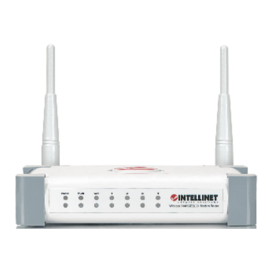
Page 10: Front Panel
Front Panel On the router’s front panel, there are LEDs that inform you of the router’s current status, as explained below. Status Description POWER (Green) Router is switched on and correctly powered. WLAN (Yellow) Wireless LAN WPS is on. Wireless LAN is disabled. Blinking Wireless traffic is transmitting or receiving. - Page 11 Installation 1. Connect the router to your ADSL cable through the supplied RJ11 cable. 2. Connect the router to your PC, hub or switch by attaching the Ethernet cable to the LAN port of the router. 3. Connect the power adapter to the power jack on the rear panel of the router. 4.
-
Page 12: Setup Wizard
3 Setup Wizard This router provides a Setup Wizard tool to configure the ADSL settings. This wizard collects some ISPs’ ADSL settings so that you can easily configure the router’s ADSL settings by only selecting the ISP vendor from the wizard. If you cannot find your ISP from the list in the wizard, manually set the ISP information through the wizard. - Page 13 3. The wizard will run and try to search for the router. If the router is found, the wizard will guide you to Step 5.
- Page 14 4. If the router cannot be found, enter the IP address and the password of the router to search again. Click “Next” to continue. 5. The wizard will automatically select the country you are in by checking the language of the operating system in your computer and then advance to the Select ISP screen.
-
Page 15: Automatically Set The Isp
3.2 Automatically Set the ISP If you can find the ISP from the wizard, follow the procedures below to let the wizard set the ISP settings automatically. 1. Select the ISP of your ADSL service. 2. Enter the username and password that your ISP has provided to you, if needed. - Page 16 3. Click “Save” to save the settings and reboot the router. 4. After saving and rebooting the router, the ISP settings are completed. The wizard will then help to set your computer to obtain an IP address from the router automatically. NOTE 1: To use the router to access the Internet, the IP address of each PC needs to be set in the same network segment as the router.
- Page 17 5. The wizard will try to connect to the ISP you have selected. If the connection fails, run the wizard to select the ISP again. 6. If you successfully connect to the ISP, you will see the screen below. To configure additional settings, click “Advanced Settings”...
-
Page 18: Manually Set The Isp
5.3 Manually Set the ISP If you cannot find the ISP from the wizard, follow the steps below to set the ISP settings manually. Before configuring the ISP manually, check with your ISP (Internet service provider) as to what kind of service is provided, such as PPPoE, PPPoA or RFC1483/2684. - Page 19 2. Check with your ISP as to the connection type of the ADSL line. Select the Connection Type and click “Next.” 3. Input the VPI, VCI and encapsulation data supplied by your ISP. If the Connection Type is “Static IP Address,” you need to input the IP address information supplied by your ISP.
- Page 20 4. Enter the username and password that your ISP has provided to you, if needed. Click “Next.” 5. Click “Save” to save the settings and reboot the router. 6. After saving and rebooting the router, the ISP settings are completed. The wizard will then help to set your computer to obtain an IP address from the...
- Page 21 router automatically. NOTE 1: To use the router to access the Internet, the IP address of each PC needs to be set in the same network segment as the router. The wizard will help to set the proper IP address for your computer. NOTE 2: By default, the router’s DHCP server is enabled.
- Page 22 8. If you successfully connect to the ISP, you will see the screen below. To configure additional settings, click “Advanced Settings” to go to the Web management of the router, or click “Finish” to close the wizard.
-
Page 23: Ip Address Setting
4 IP Address Setting To use the router to access the Internet, the PCs in the network must have am Ethernet adapter installed and be connected to the router either directly or through a hub or switch. The TCP/IP protocol of each PC needs to be installed, and the IP address of each PC has to be set in the same subnet as the router. -
Page 24: Windows Xp
5. Click “OK” to confirm the setting. Your PC will now obtain an IP address automatically from your router’s DHCP server. NOTE: Make sure that the router’s DHCP server is the only DHCP server available on your LAN. Windows XP 1. -
Page 25: Windows 2000
5. Click “OK” to confirm the setting. Your PC will now obtain an IP address automatically from your router’s DHCP server. NOTE: Make sure that the router’s DHCP server is the only DHCP server available on your LAN. Windows 2000 1. - Page 26 5. In the Internet Protocol (TCP/IP) Properties window, select “Obtain an IP address automatically” and “Obtain DNS server address automatically,” as shown on the following screen. 6. Click “OK” to confirm the setting. Your PC will now obtain an IP address automatically from your router’s DHCP server.
-
Page 27: Web Management Configuration
5 Web Management Configuration Once you have configured your PCs to obtain an IP address automatically, the router’s DHCP server will automatically give your LAN clients an IP address. By default, the router’s DHCP server is enabled so you can obtain an IP address automatically. - Page 28 Quick Setup (Section 5.1) The Quick Setup Wizard provides only the necessary configurations to connect your router to your Internet service provider (ISP). General Setup (Section 5.2) The router supports advanced functions like virtual server, access control, hacker attack detection and DMZ. It’s highly recommended that you keep the default settings.
-
Page 29: Quick Setup
5.1 Quick Setup The Quick Setup section is designed to get you using the router as quickly as possible. Before configuring the router, check with your ISP (Internet service provider) as to what kind of the service is provided, such as PPPoE, PPPoA or RFC1483/2684. - Page 30 2. Select the country you’re in and your ISP (Internet service provider). 3. Enter the username and password your ISP has provided to you, if needed. Click “Finish” to save the settings. 4. Click “Commit and Reboot” to reboot the router.
-
Page 31: General Setup
5.2 General Setup Start your Web browser and log on to the Web management interface of the router, then either click “General Setup” on the left menu or click the “General Setup” link at the upper-right corner of the Web management interface. 5.2.1 System This screen includes the basic configuration tools for the router’s remote management access function. -
Page 32: Password Settings
When you finish, click “Apply Changes.” You’ll see the following message displayed on Web browser. Click “Continue” to save the settings made and go back to the Web management interface; click “Apply” to save the settings and restart the router so the settings will take effect after it reboots. -
Page 33: Remote Management
If you see the following message: It means the content in the “Current Password” field is wrong. Click “OK” to go back to the previous menu and input the current password again. If the current and new passwords are correctly entered, after you click “Apply” you’ll be prompted to input your new password: Use the new password to enter the Web management interface again, and you should be able to log in with the new password. - Page 34 Parameter Description Check/un-check the services on the LAN column to allow/ disallow the services access from the LAN side. Check/un-check the services on the WAN column to allow/ disallow the services access from the WAN side. WAN Port This field allows the user to specify the port corresponding to the service.
-
Page 35: Snmp
Click “Continue” to save the settings made and go back to the Web management interface; click “Apply” to save the settings made and restart the router so the settings will take effect after it reboots. 5.2.1.4 SNMP Simple Network Management Protocol (SNMP) is a troubleshooting and management protocol that uses the UDP protocol on Port 161 to communicate between clients and servers. -
Page 36: Wan
Community name Name of the write-only community. This write-only (write-only) community allows write operation to the objects defines as read-writable in the MIB. When you finish, click “Apply Changes.” You’ll see the following message displayed on Web browser. Click “Continue” to save the settings made and go back to the Web management interface;... - Page 37 PPPoE VPI/VCI, VC-based/LLC-based multiplexing, Username, Password (and Service Name). PPPoA VPI/VCI, VC-based/LLC-based multiplexing, Username, Password. RFC1483 Bridged VPI/VCI, VC-based/LLC-based multiplexing to use Bridged Mode. RFC1483 Routed VPI/VCI, VC-based/LLC-based multiplexing, IP Address, Subnet Mask, Gateway Address, and Domain Name System (DNS) IP Address (It is a fixed IP Address). RFC1483 MER VPI/VCI, VC-based/LLC-based multiplexing, IP Address, Subnet Mask, Gateway Address, and Domain Name...
- Page 38 Parameter Description VPI is a virtual path that determines the way an ATM cell should be routed. The VPI is an 8-bit (in UNI) or 12-bit (in NNI) number that is included in the header of an ATM cell. The valid range for the VPI is 0 to 255. Enter the VPI assigned by the ISP.
- Page 39 Idle Time (ms) “Idle Time” is set to stop the connection when the network traffic is not sending or receiving after an idle time. Type Fixed IP – Set the static IP Address to the router. Enter the IP address your ISP has assigned. DHCP –...
-
Page 40: Atm Setting
When you finish, click “Apply Changes.” You’ll see the following message displayed on Web browser. Click “Continue” to save the settings made and go back to the Web management interface; click “Apply” to save the settings made and restart the router so the settings will take effect after it reboots. - Page 41 is included in the header of an ATM cell. The valid VCI range is 32 to 65535. Enter the VCI assigned by the ISP. UBR (Unspecified Bit Rate) – Select UBR for applications that are non-time sensitive, such as e-mail. CBR (Constant Bit Rate) –...
-
Page 42: Adsl Setting
Click “Continue” to save the settings made and go back to the Web management interface; click “Apply” to save the settings made and restart the router so the settings will take effect after it reboots. 5.2.2.3 ADSL Setting The screen allows you to select any combination of DSL modes. Parameter Description ADSL modulation... -
Page 43: Dns
carry any data. Click “Tone Mask” to mask the tone number you have selected or all the tone numbers. When you finish, click “Apply Changes.” You’ll see the following message displayed on Web browser. Click “Continue” to save the settings made and go back to the Web management interface;... -
Page 44: Ddns
Parameter Description Attain DNS Select this item if you want to use the DNS servers Automatically obtained from ISP. Set DNS Manually Select this item to specify up to three DNS IP addresses. When you finish, click “Apply Changes.” You’ll see the following message displayed on Web browser. -
Page 45: Rip
Parameter Description Enable Check the box to enable DDNS function. DDNS Provider Select your DDNS service provider here. This router supports DynDNS and TZO service providers. Host Name Enter the domain name you’ve obtained from the DDNS service provider. Username Enter the username assigned by the DDNS service provider. - Page 46 to share routes because all Internet data from the network is sent to the same ISP gateway. You may want to configure RIP if any of the following circumstances apply to your network: • Your home network setup includes an additional router or RIP-enabled PC (other than this one).
-
Page 47: Lan
RIP Config Table The RIP you have configured will be listed in the table. If you want to delete some settings, select the settings and click “Delete Selected.” When you finish, click “Apply Changes.” You’ll see the following message displayed on Web browser. Click “Continue”... - Page 48 Parameter Description Interface Name The interface name is “br0.” IP Address Enter the IP address of the ADSL router for the local user to access the router’s Web screen. By default, the IP address is 192.168.2.1. Subnet Mask Enter the subnet mask of the ADSL router. By default, the subnet mask is 255.255.255.0.
-
Page 49: Dhcp Mode
5.2.3.1 DHCP Mode You can configure your network and the router to use the Dynamic Host Configuration Protocol (DHCP). This screen allows you to select the DHCP mode that this router will support. There are two different DHCP modes: DHCP Server and DHCP Relay. When the router is acting as a DHCP server, configure it on the DHCP Server screen;... -
Page 50: Dhcp Server
Parameter Description DHCP Server Address Specify the IP address of your ISP’s DHCP server. Requests for IP information from your LAN interface will be passed to the default gateway, which should route the request appropriately. When you finish, click “Apply Changes.” You’ll see the following message displayed on Web browser. - Page 51 Parameter Description LAN IP Address The current IP address of the router. Subnet Mask The current subnet mask of the router. IP Pool Range You can select a particular IP address range for your DHCP server to issue IP addresses to your LAN clients. By default, the IP range is from 192.168.2.100 to 192.168.2.200.
-
Page 52: Arp Table
5.2.3.4 ARP Table ARP is the Address Resolution Protocol. Its job is to match MAC addresses to IP addresses and vice versa (matching IP addresses to MAC addresses). This screen lists the IP addresses and the matched MAC addresses in the network. 5.2.3.5 Bridging You can enable/disable the Spanning Tree Protocol and set the MAC address aging time on this screen. -
Page 53: Wireless
When you finish, click “Apply Changes.” You’ll see the following message displayed on Web browser. Click “Continue” to save the settings made and go back to the Web management interface; click “Apply” to save the settings made and restart the router so the settings will take effect after it reboots. - Page 54 Parameter Description Disable Wireless LAN Check to deactivate the wireless function of the router. Interface When this is activated, the router will not be an access point for other wireless clients to connect wirelessly. Band Select the radio band from one of the following options: •...
-
Page 55: Advanced Settings
Control Sideband Select the upper band or lower band for your radio frequency. While “Upper” is selected, the channel options are from 5 to 11. While “Lower” is selected, the channel options are from 1 to 7. Channel Number This is the radio channel used by the wireless LAN. All devices in the same wireless LAN should use the same channel. - Page 56 Parameter Description Authentication Type There are three authentication types: Open System, Shared Key and Auto. • Open System authentication is not required to be successful, as a client may decline to authenticate with any other particular client. • Shared Key is only available if the WEP option is implemented.
- Page 57 • Auto is the default authentication algorithm. It will change its authentication type automatically to fulfill a client’s requirement. Fragmentation Fragment Threshold specifies the maximum size of a Threshold packet during the fragmentation of data to be transmitted. If you set this value too low, it will result in bad performance.
- Page 58 transmit the network name (SSID) into open air at regular intervals. This feature is intended to allow clients to dynamically discover the router. If this option is disabled, the router will hide its SSID. When this is done, the clients cannot directly discover the router and MUST be configured with the SSID for access to the router.
-
Page 59: Security
5.2.4.3 Security This router provides complete wireless LAN security functions, including WEP, IEEE 802.1x, IEEE 802.1x with WEP, WPA with pre-shared key and WPA with RADIUS. With these security functions, you can protect your wireless LAN from illegal access. Make sure your wireless stations use the same security function. Parameter Description Encryption... - Page 60 WPA2 (AES) for data encryption. The actual selection of the encryption methods will depend on the clients. Use 802.1x IEEE 802.1x is an authentication protocol. Every user Authentication must use a valid account to log in to this wireless router before accessing the wireless LAN.
-
Page 61: Access Control
RADIUS Server password of the external RADIUS server. When you finish, click “Apply Changes.” You’ll see the following message displayed on Web browser. Click “Continue” to save the settings made and go back to the Web management interface; click “Apply” to save the settings made and restart the router so the settings will take effect after it reboots. -
Page 62: Wps
clients. If you enable this function, set the MAC address of the wireless clients that you want to filter. Disable disables this function. Allow Listed only allows the wireless clients with the MAC address you have specified access to the router. Deny Listed means the wireless clients with the MAC address you have specified will be denied access to the router. - Page 63 Parameter Description Disable WPS Check to disable Wi-Fi Protected Setup. WPS Status When the settings are factory defaults (out of the box), it is set to an open security and unconfigured state. “WPS Status” will display it as “UnConfigured.” If it already shows “Configured,”...
-
Page 64: Qos
or eight numeric digits. If users enter an eight-digit PIN with checksum error, a warning message pops up. If users insist on this PIN, the router will take it. When you finish, click “Apply Changes.” You’ll see the following message displayed on Web browser. - Page 65 Parameter Description IP QoS Click the radio button to enable or disable the function. Default QoS Select the default mode of QoS from the menu. • IP Precedence: In QoS, a three-bit field in the ToS byte of the IP header (see RFC 791). Using IP Precedence, a network administrator can assign values from 0 (the default) to 7 to classify and prioritize types of traffic.
-
Page 66: Nat (Network Address Translations)
Precedence Select this field to mark the IP precedence bits in the packet that match this classification rule. The IP (Internet Protocol) uses the ToS (Type of Service) field to provide an indication of the quality of service desired. These parameters are to be used to guide the selection of the actual service parameters when transmitting an IP datagram through a particular network. -
Page 67: Port Forwarding
5.2.6.1 Port Forwarding Port Forwarding allows you to re-direct a particular range of service port numbers (from the Internet) to a particular LAN IP address. It helps you to host some servers behind the router’s NAT firewall. Parameter Description Port Forwarding Check to enable or disable the port-forwarding feature. -
Page 68: Port Mapping
Forwarding Table select the items and click “Delete Selected.” To remove all settings, just click “Delete All.” When you finish, click “Apply Changes.” You’ll see the following message displayed on Web browser. Click “Continue” to save the settings made and go back to the Web management interface;... - Page 69 Parameter Description Disabled/Enabled Click the radio button to enable or disable the feature. If disabled, all interfaces belong to the default group. Interface groups To manipulate a mapping group: 1. Select a group from the table. 2. Select interfaces from the available/grouped interface list and add to the grouped/available interface list using the arrow buttons to manipulate the required mapping of the ports.
-
Page 70: Upnp
Click “Continue” to save the settings made and go back to the Web management interface; click “Apply” to save the settings made and restart the router so the settings will take effect after it reboots. 5.2.6.3 UPNP When the UPnP function is enabled, the router can be detected by UPnP- compliant systems such as Windows XP. -
Page 71: Igmp Proxy
5.2.6.4 IGMP Proxy When IGMP Proxy (Internet Group Management Protocol Proxy) is enabled, the router can make intelligent multicast forwarding decisions by examining the contents of each frame’s IP header. Without the function, the router will broadcast the multicast packets to each port and may create excessive traffic on the network and degrade the performance of the network. -
Page 72: Firewall
Click “Continue” to save the settings made and go back to the Web management interface; click “Apply” to save the settings made and restart the router so the settings will take effect after it reboots. 5.2.7 Firewall The Firewall section contains several features that are used to deny or allow traffic from passing through the router 5.2.7.1 IP/Port Filtering The IP/Port Filtering feature allows you to deny/allow specific services or... - Page 73 listed in the table from connecting to the Internet. Direction Select the traffic forwarding direction: outgoing or incoming. Protocol There are three options available: TCP, UDP and ICMP. Rule Action Deny or allow traffic when matching this rule. Source IP Address Enter the start IP address that will be monitored.
-
Page 74: Mac Filtering
5.2.7.2 MAC Filtering The MAC Filtering feature allows you to define rules to allow or deny frames through the router based on source MAC address, destination MAC address and traffic direction. Parameter Description Outgoing Default Specify the default action on the LAN-to-WAN (Traffic-to- Action Internet) forwarding path. - Page 75 Source MAC Address This must be in 12-digit hexadecimal format; for example, “00-d0-59-c6-12-43.” Destination MAC This must be in 12-digit hexadecimal format; for example, Address “00-d0-59-c6-12-50.” Current Filter Table To remove some filter rules from the Current Filter Table, select the MAC address you want to remove and click “Delete Selected.”...
-
Page 76: Url Blocking
5.2.7.3 URL Blocking This screen is used to block some URL addresses or keywords. Parameter Description URL Blocking Enable or disable the URL Blocking function. FQDN Enter the FQDN which you want to block. A FQDN is a complete DNS name. For example, “www.yahoo.com.” URL Blocking Table The FQDN settings will be listed in the table. -
Page 77: Domain Blocking
When you finish, click “Apply Changes.” You’ll see the following message displayed on Web browser. Click “Continue” to save the settings made and go back to the Web management interface; click “Apply” to save the settings made and restart the router so the settings will take effect after it reboots. -
Page 78: Routing Configuration
Parameter Description Check this item to enable the Domain Blocking feature. Domain Blocking The blocked domain. If the URL of the Mars Yahoo Web Domain site is ma.yahoo.com, the domain can be yahoo.com. Delete Selected/All To delete a specific Domain Block entry, check the “Select”... - Page 79 Destination The destination can be specified as the IP address of a subnet or a specific host in the subnet. It can also be specified as all zeros to indicate the route should be used for all destinations for which no other route is defined (this is the route that creates the default gateway).
-
Page 80: Acl Configuration
5.2.7.6 ACL Configuration The Access Control List (ACL) is a list of permissions attached to the router that specifies who is allowed to access this router. If ACL is enabled, all hosts cannot access this router except for the hosts with an IP address in the ACL table. Parameter Description ACL Capability... -
Page 81: Dmz
Click “Continue” to save the settings made and go back to the Web management interface; click “Apply” to save the settings made and restart the router so the settings will take effect after it reboots. 5.2.7.7 DMZ The DMZ Host is a local computer exposed to the Internet. When setting a particular internal IP address as the DMZ Host, all incoming packets will be checked by the firewall and NAT algorithms, then passed to the DMZ Host. -
Page 82: Status
Click “Continue” to save the settings made and go back to the Web management interface; click “Apply” to save the settings made and restart the router so the settings will take effect after it reboots. 5.3 Status This screen displays the ADSL modem/router’s current status and settings. This information is read-only except for the PPPoE/PPPoA channel, for which you can connect/disconnect the channel on demand. -
Page 83: Interface
5.3.1 Interface You can view statistics on the processing of IP packets on the networking interfaces. You will not typically need to view this data, but you may find it helpful when working with your ISP to diagnose network and Internet data transmission problems. -
Page 84: Adsl
5.3.2 ADSL This screen shows the ADSL line statistic information. -
Page 85: Tools
5.4 Tools The Tools section includes the basic configuration tools, such as Back Up, Restore Configuration Settings, Upgrade System Firmware and Diagnostic Test. 5.4.1 Configuration Tools This screen allows you to back up the current settings to a file or restore the settings from the file that was saved previously. -
Page 86: Firmware Upgrade
Load Settings from File Click “Browse” to search for a file you saved before, and click “Upload” to restore the saved configuration. Restore Settings to Click “Reset” to force the router to perform a power reset Default and restore the original factory settings. 5.4.2 Firmware Upgrade This screen allows you to upgrade the firmware for the router. -
Page 87: Atm Loopback
5.4.4 ATM Loopback In order to isolate ATM interface problems, you can use ATM OAM loopback cells to verify connectivity between VP/VC endpoints, as well as segment endpoints within the VP/VC. This screen allows you to use ATM ping to test the reachability of a segment endpoint or a connection endpoint. -
Page 88: Diagnostic Test
5.4.5 Diagnostic Test The Diagnostic Test screen shows the test results for the connectivity of the physical layer and protocol layer for both LAN and WAN sides. 5.4.6 Reboot Whenever you use the Web configuration to change system settings, the changes are initially placed in temporary storage. -
Page 89: Troubleshooting
6 Troubleshooting The LAN LED on the front panel does not light up. STEPS CORRECTIVE ACTION Check the Ethernet cable connections between your router and the computer or hub. Check for faulty Ethernet cables. Make sure your computer’s Ethernet card is working properly. If these steps fail to correct the problem, contact your local distributor for assistance. - Page 90 The following procedures will help you to check the current IP address setting of your computer. You can compare if your computer and the router’s IP addresses are in the same subnet. Step 1: Click “Start” and select “Run.” Step 2: Enter “cmd” in the “Open” text field and click “OK.” Step 3: Input “ipconfig/al”l and press <Enter>...
- Page 91 I forget my login username and/or password. STEPS CORRECTIVE ACTION If you have changed the password and have now forgotten it, you will need to upload the default configuration file. This will erase all custom configurations and restore all of the factory defaults, including the password.
- Page 92 Initialization of the ADSL connection failed. STEPS CORRECTIVE ACTION Check the cable connections between the ADSL port and the wall jack. The ADSL LED on the rear panel of the router should be on. Check that the VPI, VCI, Type of Encapsulation and Type of Multiplexing settings are the same as what you collected from your ISP.
-
Page 93: Glossary
7 Glossary 10Base-T It is an Ethernet standard for a local area network (LAN). 10Base-T uses a twisted pair cable with a maximum length of 100 meters. ATM is an adaptation layer that defines the rules governing segmentation and reassembly of data into cells. Different AAL types are suited to different traffic classes. - Page 94 DNS Server IP Address DNS stands for domain name system, which allows Internet servers to have a domain name (such as www.ADSLrouter.com) and one or more IP addresses (such as 192.34.45.8). A DNS server keeps a database of Internet servers and their respective domain names and IP addresses, so that when a domain name is requested (as in typing “...
- Page 95 MAC Address MAC stands for media access control. A MAC address is the hardware address of a device connected to a network. The MAC address is a unique identifier for a device with an Ethernet interface. It is composed of two parts: 3 bytes of data that corresponds to the manufacturer ID (unique for each manufacturer), plus 3 bytes that are often used as the product’s serial number.
- Page 96 PPP is the Point-to-Point-Protocol. The successor to SLIP, PPP provides router- to-router and host-to-network connections over both synchronous and asynchronous circuits. PPPoA (RFC 2364) The Point-to-Point Protocol (PPP) provides a standard method for transporting multi-protocol datagrams over point-to-point links. This document describes the use of ATM Adaptation Layer 5 (AAL5) for framing PPP encapsulated packets.
- Page 97 Router A system responsible for making decisions about which of several paths network (or Internet) traffic will follow. To do this, it uses a routing protocol to gain information about the network and algorithms in order to choose the best route based on several criteria known as “routing metrics.”...
-
Page 98: Specifications
8 Specifications Standards • IEEE 802.3 (10Base-T Ethernet) • IEEE 802.3u (100Base-TX Fast Ethernet) • IEEE 802.11b (11 Mbps Wireless LAN) • IEEE 802.11g (54 Mbps Wireless LAN) • IEEE 802.11n Draft 2.0 (300 Mbps Wireless LAN) • ADSL2+ (ITU G.992.5) up to 24 Mbps •... - Page 99 - URL filter • Supports UPnP (Universal Plug and Play) • Supports DHCP (client/server) • Supports VPN PPTP, L2TP and IPsec passthrough Wireless • Chipset: Realtek RTL8192SU • Wireless frequency range: 2.4 – 2.4835 GHz • Modulation technologies: - 802.11b: Direct Sequence Spread Spectrum (DSSS): DBPSK, DQPSK, CCK - 802.11g: Orthogonal Frequency Division Multiplexing (OFDM): BPSK, QPSK, 16QAM, 64QAM - 802.11n: Orthogonal Frequency Division Multiplexing (OFDM): BPSK, QPSK,...
-
Page 100: Package Contents
- 2T2R MIMO mode (2 transmitter, 2 receiver) LEDs • Power • WLAN • WPS • ADSL Link/Act • LAN 1-4 Link/Act Environmental • Dimensions: 187 (W) x 100 (D) x 30 (H) mm (7.3 x 3.9 x 1.2 in.) •... - Page 101 WASTE ELECTRICAL & ELECTRONIC EQUIPMENT Disposal of Electric and Electronic Equipment (applicable in the European Union and other European countries with separate collection systems) ENGLISH This symbol on the product or its packaging indicates that this product shall not be treated as household waste.
- Page 102 ITALIANO Questo simbolo sui prodotto o sulla relativa confezione indica che il prodotto non va trattato come un rifiuto domestico. In ottemperanza alla Direttiva UE 2002/96/EC sui rifiuti di apparecchiature elettriche ed elettroniche (RAEEI), questa prodotto elettrico non deve essere smaltito come rifiuto municipale misto. Si prega di smaltire il prodotto riportandolo al punto vendita o al punto di raccolta municipale locale per un opportuno riciclaggio.
-
Page 103: Warranty Information
WARRANTY INFORMATION ENGLISH: For warranty information, go to www.intellinet-network.com/warranty. DEUTSCH: Garantieinformationen finden Sie unter www.intellinet-network.com/warranty. ESPAÑOL: Si desea obtener información sobre la garantía, visite www.intellinet-network.com/warranty. FRANÇAIS: Pour consulter les informations sur la garantie, visitez www.intellinet-network.com/warranty. POLSKI: Informacje dotyczące gwarancji znajdują się na stronie www.intellinet-network.com/warranty. - Page 104 All products mentioned are trademarks or registered trademarks of their respective owners. Copyright © INTELLINET NETWORK SOLUTIONS...
Need help?
Do you have a question about the 524780 and is the answer not in the manual?
Questions and answers