Table of Contents
Advertisement
Quick Links
Advertisement
Table of Contents

Subscribe to Our Youtube Channel
Related Manuals for Intellinet 524957


Summary of Contents for Intellinet 524957
- Page 1 4-PORT BROADBAND ROUTER USER MANUAL MODEL 524957 INT-524957-UM-1210-02...
- Page 2 INTRODUCTION Thank you for purchasing the INTELLINET NETWORK SOLUTIONS ™ 4-Port Broadband Router, Model 524957. Combining a router, firewall and four-port Fast Ethernet switch, this handy device lets you experience fast speeds as you surf the Web, download music or photos, and play online games. A DHCP server that automatically assigns IP addresses to users on the LAN —...
-
Page 3: Table Of Contents
TABLE OF CONTENTS 1 Hardware Installation... 4 1.1 Rear Panel Ports & Jacks... 4 1.2 Front Panel LEDs ... 5 2 Network Settings ... 5 2.1 IP Address Setup ... 5 2.2 Confirming the Connection ... 14 2.3 Logging In to the Web Browser ... 16 3 Router Setup ... -
Page 4: Hardware Installation
1 HARDWARE INSTALLATION Using the included RJ45 Ethernet cable (and more, as needed), make your 4-Port Broadband Router network connections by following the steps below and referring to the Port and LED descriptions (presented from left to right). 1. Turn off all devices to be incorporated into the network, including any PCs, switches/hubs, the modem and the router. -
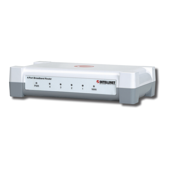
Page 5: Front Panel Leds
1.2 Front Panel LEDs PWR — This lights when the router is turned on. 4-1 — These correspond to the four LAN ports on the router’s rear panel. Lighted indicates a successful connection; blinking means data is being transmitted or received through that port. WAN —... - Page 6 the item that has an arrow (→) pointing to the network card installed on your computer. Do not choose the TCP/IP listing that has the words “Dial Up Adapter” beside it. 5. Click “Properties” to display the TCP/IP Properties dialog box. 6.
- Page 7 3. Right-click on the “Local Area Connections” icon to display the pop-up menu, then click “Properties.” 4. Highlight “Internet Protocol (TCP/P)” and click “Properties.” NETWORK SETTINGS...
- Page 8 5. Select “Obtain an IP address automatically” and “Obtain DNS server address automatically”; click “OK” to return to the previous screen. 6. When the Local Area Connection Properties screen displays again, click “OK.” NETWORK SETTINGS ...
- Page 9 2.1.3 Windows XP 1. On your PC’s desktop, click “Start” and go to the Control Panel. 2. Select “Network and Internet Connections.” 3. Click “Network Connections.” NETWORK SETTINGS...
- Page 10 4. Right-click on the “Local Area Connections” icon to display the pop-up menu, then click “Properties.” 5. On the subsequent Local Area Connection Properties screen, select “Internet Protocol (TCP/IP)” and click “Properties.” NETWORK SETTINGS ...
- Page 11 6. Select both “Obtain an IP address automatically” and “Obtain DNS server address automatically”; then click “OK.” 7. When Local Area Connection Properties displays again, click “Close.” NETWORK SETTINGS...
- Page 12 2.1.4 Windows Vista/7 1. On your PC’s desktop, click “Start” and go to the Control Panel. 2. Click “Network and Sharing Center.” 3. With the Network and Sharing Center screen displayed, select “Manage network connections.” NETWORK SETTINGS ...
- Page 13 4. Right-click on the “Local Area Connection” icon to display the pop- up menu, then click “Properties.” 5. Highlight “Internet Protocol Version 4 (TCP/IPv4)” and click “Properties.” NETWORK SETTINGS...
-
Page 14: Confirming The Connection
6. Select both “Obtain an IP address automatically” and “Obtain DNS server address automatically”; then click “OK.” 7. When Local Area Connection Properties displays again, click “OK” to close the screen. 2.2 Confirming the Connection Once the configuration for obtaining an IP address is complete, you can use the ping command to verify that the computer is able to communicate with the router. - Page 15 C:\Documents and Settings\admin>ping 192.168.2.1 Pinging 192.168.2.1 with 32 bytes of data: Reply from 192.168.2.1: bytes=32 time=1ms TTL=64 Reply from 192.168.2.1: bytes=32 time=1ms TTL=64 Reply from 192.168.2.1: bytes=32 time=1ms TTL=64 Reply from 192.168.2.1: bytes=32 time=1ms TTL=64 Ping statistics for 192.168.2.1: Packets: Sent = 4, Received = 4, Lost = 0 (0% loss), Approximate round trip times in milli-seconds: Minimum = 1ms, Maximum = 1ms, Average = 1ms If the computer fails to connect to the router, the Command window...
-
Page 16: Logging In To The Web Browser
2.3 Logging In to the Web Browser 1. Open a Web browser (Microsoft Internet Explorer, Firefox, Safari, etc.) on the computer you’ve just connected to the router and enter the IP address (192.168.2.1) in the address bar. Press <Enter> on your keyboard to display a login window (below). 2. - Page 17 Once you’ve logged in, the router’s user interface will display. ROUTER SETUP...
-
Page 18: Router Setup
3 ROUTER SETUP With the user interface displayed, you have the option of proceeding with the Quick Setup procedure (Section 3.1 below) or selecting any of the 10 additional menu options (Admin, WAN, etc. — Sections 3.2–3.11), which allow you to modify the default settings to customize your router and network configuration. - Page 19 or you can select “Manual Select,” which presents you with four options. Select one and click “Next” or click “Back” to return to the previous screen. NOTE: Additional configuration options for each of these four connection types are explained in detail in Section 3.3: WAN.
- Page 20 Dynamic IP Address — This connection type means you obtain an IP address from your Internet service provider (ISP) automatically. (ISPs that supply a cable modem always use this.) Click “Next” to advance to the next screen. Clone MAC: The WAN port of the router has a unique Media Access Control (MAC) address assigned to it referred to as “Default MAC.”...
- Page 21 advance to the next screen. IP Address: Enter the address provided by your ISP. Subnet Mask: Enter the address provided by your ISP. Gateway IP: This is provided by your ISP. PPPoE — This connection type (Point-to-Point Protocol over Ethernet) is typically used with DSL and ADSL service. Click “Next” to advance to the next screen.
- Page 22 3. When the appropriate fields have been filled in for the selected connection type, click “Next” to advance to the DNS Server screen. • Static DNS Server: Select to enable/disable the server. • Primary DNS: Your ISP will provide at least one Domain Name System (DNS) IP address.
-
Page 23: Admin
3.2 Admin This submenu presents numerous basic, yet popular, configuration options and features, including modifying your network password. NOTE: As you finish making changes to the settings on any of the menu screens, click “OK” to implement the changes or click “Cancel” to clear the fields and revert to previous selections. -
Page 24: System Settings
3.2.2 System Settings NTS Server: For reference. Time Zone: Select from the drop-down menu. Daylight Saving: Select to enable/disable, then set the date range using the drop-down menus. Host Name: For reference. NAPT: Select to enable/disable Network Address Port Translation. 3.2.3 Firmware Upgrade This important function allows you to upgrade the router’s firmware. - Page 25 firmware upload procedure, as such an occurence can cause damage both to the file and the router itself. 3.2.4 Configuration Restore Factory Default: Select to put everything into factory configuration. Make sure you have made a copy of what you’ve configured.
-
Page 26: Log Settings
3.2.5 Tools Reboot: Click to restart the router. 3.2.6 Language Language: Make a selection from the drop-down menu. 3.2.7 Log Settings Settings: This section displays the logs of various activites and events, and also allows you to send these records to another location via e-mail. -
Page 27: Wan
SMTP Server: Enter the address of the Simple Mail Transfer Protocol server that will be used to send the log information. Sender/Receiver Email Address: Enter the addresses that logs will be sent from/to, then select “Email Log” and click “Send.” 3.2.8 Logout Click “OK”... - Page 28 Primary DNS: Your ISP will provide at least one Domain Name System (DNS) IP address. (DNS translates readable/recognizable domain names into numerical IP addresses.) Enter the IP address of your DNS server here. Secondary DNS: As an option, you can enter the IP address of a backup DNS server here.
- Page 29 users should use the value 1492.You can set MTU manually, and you should leave this value in the 576 to 1500 range. NOTE: If the value entered isn’t in accord with the value the ISP provides, it can cause problems, such as failure to send e-mail or to browse. (If such a problem occurs, contact your ISP for information about correcting the MTU value.) Primary DNS: Your ISP will provide at least one Domain Name System...
- Page 30 3.3.3 PPPoE This connection type (Point-to-Point Protocol over Ethernet) is typically used with DSL and ADSL service. Address Mode: Select whichever service you’re provided. IP Address: If you select Static PPPoE, you must enter an IP address here. PPPoE Account: Enter the PPPoE username provided by your ISP. PPPoE Password: Enter the PPPoE password provided by your ISP.
- Page 31 a problem occurs, contact your ISP for information about correcting the MTU value.) Primary DNS: Your ISP will provide at least one Domain Name System (DNS) IP address. (DNS translates readable/recognizable domain names into numerical IP addresses.) Enter the IP address of your DNS server here.
- Page 32 MTU: Maximum Transmission Unit specifies the largest packet size permitted for network transmission. Most DSL users should use the value 1492. You can set MTU manually, but it should be left in the 576 to 1500 range. NOTE: If the value entered isn’t in accord with the value the ISP provides, it can cause problems, such as failure to send e-mail or to browse.
-
Page 33: Lan
3.4 LAN This menu — with its two submenu screens: LAN Settings and DHCP Client List — presents options for configuring your local area network. 3.4.1 LAN Settings IP Address: This is the router’s LAN port IP address (your LAN clients’ default gateway IP address), shown with the default value. -
Page 34: Dhcp Client List
which the connected client computers are instructed to request a new IP address from the router. DNS Proxy: When activated, the router acts as a DNS server in your network, which means that the computer sends the DNS request to the router, which in turn queries the ISP’s DNS server. -
Page 35: Nat
3.5 NAT The network address translation (NAT) menu presents options that make it possible to open ports, create a DMZ and perform other functions. 3.5.1 Virtual Server Some games, servers and applications don’t work in conjunction with NAT unless a virtual server is established to provide WAN-to-LAN port mapping. -
Page 36: Port Triggering
3.5.2 Port Triggering The port trigger module dynamically registers virtual server rules when any IP host generates the packet from the specified trigger protocol and port. The port trigger module uses a forward protocol type and port number, and uses the IP address of the host that generates the trigger packet when it registers a rule. - Page 37 network, such as Web servers, FTP servers, e-mail servers and other specialized Internet applications (for example, videoconferencing or online gaming). When users send this type of request to your network via the Internet, the router will forward the request to the appropriate PC. Enabled: Select to enable/disable the function.
- Page 38 from being established. You should leave this in the 0-65535 range. NetMeeting / H323/Netmeeting Passthrough: To accept the connection request from any outside NetMeeting client, the virtual server for H323/Netmeeting (Port 1720) must be enabled. 3.5.5 DMZ Enabled: Select to enable/disable the function. Public IP Address: Make a selection from the drop-down menu.
- Page 39 time to one PC. The Port Forwarding feature is more secure because it only opens the ports you want to be opened, while DMZ hosting opens all the ports of a computer, exposing the computer so the Internet can see it. •...
-
Page 40: Firewall
3.6 Firewall This series of submenu options lets you establish a variety of network usage and access limits for better control and security. 3.6.1 Firewall Options Enabled: Select to enable/disable the items selected or the limits established in the Options table. 3.6.2 Client Filtering This screen allows you to block Internet access for local clients based on IP addresses, application types and time of day. - Page 41 Enable: Select to establish rules based on the configuration options that follow. IP Address: Enter the address (or the range of addresses) you want to control. Port/Type: You can manually enter your preferences and click “Add,” which will then display your new filter configuration in the Rules Listing.
-
Page 42: Url Filtering
3.6.3 URL Filtering This screen allows you to prevent users from accessing specific Web sites using broad or narrowly defined filters. URL Filter Control: Select one of three options: “Disable URL Filter function”; “Deny Internet Access for the following URL addresses”; and “Allow Internet Access for the following URL addresses.”... -
Page 43: Routing
want to control. The format is 00:00:00:00:00:00, using the characters 0-9 and a-f. Comment: Enter a description to differentiate among the various filters you configure. 3.7 Routing This menu presents options for optimizing pathways for information packets, thus maximizing the efficiency and speed of the router. 3.7.1 Routing Table The Routing Table List displays the current routing information as it pertains to the network. -
Page 44: Static Routing
3.7.2 Static Routing A static route is a pre-determined pathway that network information must travel in order to reach a specific host or network. Destination Network IP: Specify an address you want information packets forwarded to. Subnet Mask: Specify a subnet mask to distinguish the network and host portions of the IP address. -
Page 45: Qos
Working Mode: Select “Router” or “Default Gateway.” Listen Mode: Select “Disabled,” “RIP1,” “RIP2” or “Both” (RIP1 & 2). Supply Mode: Select “Disabled,” “RIP1,” “RIP2 (Broadcast)” or “RIP2 (Multicast).” 3.8 QoS This menu presents Quality of Service options so you can provide different priorities to different applications, users or data flows —... - Page 46 Enable Port Rate Control: Select to enable/disable the function. LAN 1--4 / WAN: For each network connection, enter a maximum uplink/downlink bandwidth. 3.8.2 DSCP Port based DSCP Enable DSCP: Select to enable/disable the function. High / Medium / Low Queue Weight: Enter your preferred values. Enable Rule: Select to enable/disable the function.
-
Page 47: Miscellaneous
Queue Map: Select a priority level from the drop-down menu. Description: Enter a description to differentiate among any number of rules that are established. 3.9 Miscellaneous This menu presents a couple of popular functions that can be configured and put to use: Universal Plug and Play (UPnP) and Dynamic Domain Name Service (DDNS). - Page 48 3.9.2 DDNS The DDNS (Dynamic Domain Name Service) feature allows you to use a domain name instead of an IP address) to access Internet sites. Before you can use this feature, however, you need to register an account for DDNS service at a DDNS service provider such as DynDNS.
-
Page 49: High Level
3.10 High Level This menu offers activation of an extra security measure to protect the network. Enabled: Select to enable/disable ARP (Address Resolution Protocol) spoofing correspondence. When enabled, this function will perform IP/MAC binding on the WAN side at the first ARP reply in order to prevent ARP spoofing, which is a type of Ethernet attack on a network. - Page 50 3.11.2 Log The router keeps a running log of events and activities, which are displayed on the screens accessed here. NOTE: When the router is rebooted, the logs are automatically cleared. ROUTER SETUP...
-
Page 51: Troubleshooting
4 TROUBLESHOOTING If you forget your password... Press the Reset button for 5 seconds or more (with the router on) to restore factory settings. The default username is “admin” and the password is “1234.” If problems arise with the cable modem connection... Confirm that the cable modem is working properly and the signal is stable. -
Page 52: Specifications
5 SPECIFICATIONS Standards • IEEE 802.3 (10Base-T Ethernet) • IEEE 802.3u (100Base-TX Fast Ethernet) General • LAN ports: 4 RJ45 10/100 Mbps data ports • LAN ports with Auto MDI/MDI-X • WAN port: 10/100 Mbps RJ45 connector • Certifications: FCC Class B, CE Router •... - Page 53 • Supports UPnP (Universal Plug and Play) • Supports DHCP (client/server) • Supports PPPoE (DSL), DHCP (cable/DSL) and static IP • Supports VPN PPTP L2TP pass-through LEDs • Power • WAN Link/Act • LAN 1-4 Link/Act Environmental • Dimensions: 155 (W) x 85 (L) x 35 (H) mm (6.1 x 3.3 x 1.4 in.) •...
-
Page 54: Federal Communications Commission
WASTE ELECTRICAL & ELECTRONIC EQUIPMENT Disposal of Electric and Electronic Equipment (applicable in the European Union and other European countries with separate collection systems) This symbol on the product or its packaging indicates that this product shall not be treated as household waste. Instead, it should be taken to an applicable collection point for the recycling of electrical and electronic equipment. - Page 56 INTELLINET NETWORK SOLUTIONS ™ offers a complete line of active and passive networking products. Ask your local computer dealer for more information or visit www.intellinet-network.com Copyright © INTELLINET NETWORK SOLUTIONS All products mentioned are trademarks or registered trademarks of their respective owners.
Need help?
Do you have a question about the 524957 and is the answer not in the manual?
Questions and answers