Table of Contents
Advertisement
tekmarNet
Installation & Operation Manual
Introduction
The tekmarNet
provides operation for:
•
One Stage Radiant Floor Heat,
Two Stage Heat Pump for Heat &
Cool, One Stage Backup Heat
Or
•
Two Stage Heat, Two Stage Cool
And includes
•
One Stage Fan Control
•
Humidity Control
A Watts Water Technologies Company
®
Thermostat 557
®
Thermostat 557
Energy Saving Features
•
Programmable Schedule
•
Zone Synchronization
•
Zone Post Purge
•
Warm Weather Shut Down
•
Cooling Interlock
•
Auto Heating Cycle
•
Temporary Hold
•
Away Scene Key
Additional Features
•
3 Auxiliary Sensor Inputs
•
tekmarNet
Compatible
•
Touchscreen Technology
•
Outdoor & Floor Temperature
Display
•
Backlight
•
Radiant Floor Heating & Cooling
•
Freeze Protection
•
Exercising
•
Heat / Cool Priority
•
Air Group Master
•
Network Schedule Master or
Member
•
Optimum Start
•
Scenes
•
Daylight Savings Time
•
Room Temperature Limiting
•
Relative Humidity Control
1 of 48
557 _ D
Zoning
Replaces: New
®
Communication
© 2012
557_D - 08/12
08/12
Advertisement
Table of Contents
Troubleshooting

Related Manuals for Tekmar tekmarNet 557


Summary of Contents for Tekmar tekmarNet 557
-
Page 1: Energy Saving Features
557 _ D 08/12 tekmarNet ® Thermostat 557 Zoning Replaces: New Installation & Operation Manual Introduction Energy Saving Features The tekmarNet ® Thermostat 557 • Programmable Schedule provides operation for: • Zone Synchronization • One Stage Radiant Floor Heat, • Zone Post Purge Two Stage Heat Pump for Heat &... -
Page 2: Table Of Contents
Monitor Menu ......17-21 Toolbox Menu ......21-23 Setup Menu......24-30 Getting Started Congratulations on the purchase of your new tekmar ® thermostat. This manual will step through the complete installation, programming and sequence of operation for this control. At the back, there are tips for control and system troubleshooting. -
Page 3: Installation
- -- ---- - - ---- - - - - - --- - - - - - - - - - - - - - - - - - - - - - - - - - - - - - - - - - Tools Required • tekmar or jeweller screwdriver • Wire Stripper •... -
Page 4: Mounting The Thermostat
Mounting The Thermostat If a single gang box is used: If a gang box is not used: • Feed the wiring through the large • Feed the wiring through the large holes of the thermostat. holes in the thermostat. • Fasten the base of the thermostat to •... -
Page 5: Compatible Sensors
If the thermostat display continues to be off, or is cycling on and off, there may be a fault on the thermostat. If a fault is suspected, contact your tekmar sales representative for assistance. - - - - -- -- - - - - - - - -- -- - - -- - -- - - - - - - - - - - - - - - - - - - - - - - - - - - ®... -
Page 6: Switch Settings
User Test Sequence Heat Test Cool Test Step Relay(s) Closed Step Relay(s) Closed O Relay OFF Rc-O/B is opened O Relay ON Rc-O/B B Relay ON Rc-O/B B Relay OFF Rc-O/B is opened Rc-G Rc-G Y1 Heat Rc-Y1 and Rc-G Y1 Cool Rc-Y1 and Rc-G Y2 Heat... -
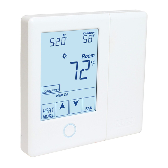
Page 7: User Interface
User Interface Home Screen The touchscreen of the 557 provides one touch access to these settings. Display Humidity, Heat & Cool settings, Floor or Adjust Outdoor temperature the Time Room Temperature Adjust the Schedule Turn the Fan on Away Key Switch between Home Button. -
Page 8: Programmable Settings
Programmable Settings Programming Menus Press and hold the Home button for 3 seconds to enter the programming menus. The thermostat returns to the last programming menu previously used. Press and hold for 3 seconds to access the programming menus. - ---- - - - - - - - - - - - - - - - - - - - - - - - - - -- - -- - -- - -- - ---- -- - - - - - - - - - - - - - - - - - - - - - - - - - - - - - - - - - - Select a Programming Menu •... -
Page 9: Set Temp Menu
Set Temp Menu (1 of 4) Setting Display Room SET HEAT ROOM Set the room heating temperature for the event. Access Level: Installer, User Range: 40 to 95°F (4.5 to 35.0°C) Conditions: Always available Default: 70°F (21.0°C) Room SET HEAT ROOM Set the room heating temperature for the event. - Page 10 Set Temp Menu (2 of 4) Setting Display WARM WEATHER SHUT DOWN Set the outdoor air temperature at which heating is suspended during the event. Range: CTRL (control), 40 to Access Level: Installer 100°F (4.5 to 38.0°C), OFF Conditions: An outdoor sensor must be available and Schedules are in use or Scenes is set to All or Default: CTRL Guest.
- Page 11 Set Temp Menu (3 of 4) Setting Display COOL MAXIMUM ROOM LIMIT Set the maximum room cooling limit. Range: 50 to 100°F (10.0 to Access Level: Installer 38.0°C) Conditions: Always available Default: 100°F (38.0°C) FLOOR MINIMUM Set the floor heating temperature while in the event.
-
Page 12: Time Menu
Set Temp Menu (4 of 4) Setting Display Set the minimum percentage the fan should operate while in the event. This provides ventilation for the building. Each 10% is 6 minutes per hour. Access Level: Installer, User Range: Auto, 10 to 90%, ON Conditions: Always available. - Page 13 Time Menu (2 of 2) Setting Display HOURS Select the current time hours. Access Level: Installer, User Range: 12 AM to 11 PM or 00 to 23 Conditions: Always available. Default: 12 AM DAY OF WEEK Select the current day of the week. Access Level: Installer, User Range: Sunday to Saturday Conditions: Always available.
-
Page 14: Schedule Menu
Schedule Menu (1 of 2) The schedule menu can operate on a 24 hour or 7 day repeating schedule. When a 24 hour schedule is selected, “SuMoTuWeThFrSa” is shown on the top of the screen to show that the event time applies to all days of the week. When a 7 day schedule is selected, each individual day of the week is shown with the event time. -
Page 15: Display Menu
Schedule Menu (2 of 2) Setting Display SCHEDULE Select if the thermostat should change the temperature automatically using a programmable schedule. OFF = Programmable schedule is not used. Zone = Applies to this thermostat only. Master 1, 2, 3, 4 = In charge of one of four available network schedules. -
Page 16: Display Menu
Display Menu (2 of 2) Setting Display BACKLIGHT Select how the display backlight operates. ON = Always full brightness. DIM = Dim when inactive, on when touched. = Dim in , off in . On when touched. = On in , off in . -
Page 17: Monitor Menu
Monitor Menu (1 of 5) Setting Display ROOM AVERAGE Current room temperature. Displays the average if there are multiple room sensors. Range: -58 to 212°F Access Level: Installer (-50.0 to 100.0°C) Conditions: Sensor 1, 2 or 3 is set to ROOM. Default: Not applicable. - Page 18 Monitor Menu (2 of 5) Setting Display SENSOR 2 The temperature measurement from the sensor 2 input wiring terminals. Range: -22 to 266°F Access Level: Installer (-30.0 to 130.0°C) Conditions: Setup menu setting Sensor 2 is set to Default: Not applicable. ROOM, FLOR, or OUT.
- Page 19 Monitor Menu (3 of 5) Setting Display ROOM HIGH The highest recorded room temperature measurement. Touch the number and the ENTER key to reset. Range: -76 to 149°F Access Level: Installer, User (-60.0 to 65.0°C) Conditions: Setup setting Room Sensor is set to ON Default: Not applicable.
- Page 20 Monitor Menu (4 of 5) Setting Display HEAT Y2 HOURS The total number of hours the second stage of heat pump has been in heating operation. Touch the number and the ENTER key to reset. Access Level: Installer, User Range: 0000 to 9999 hours Conditions: Setup menu setting Y2 TYPE is set to Default: 0000 hours HP2.
-
Page 21: Toolbox Menu
Monitor Menu (5 of 5) Setting Display COOL W2 HOURS The total number of hours the W2 relay has been operated for cooling. Touch the number and the ENTER key to reset. Access Level: Installer, User Range: 0000 to 9999 hours Conditions: Setup menu setting BACKUP W2 SOURC is set to TANK and BACKUP W2 TERM is set to Default: 0000 hours... - Page 22 2:01 to 2:24, 3:01 to 3:24 ® Conditions: tekmarNet 2 or 4 detected. Default: AUTO SOFTWARE AND TYPE VERSION Displays the software version and the tekmar type number. Access Level: Installer, User, Limited, Secure Range: 557 Conditions: Always available. Default: 557...
-
Page 23: Toolbox Menu
Toolbox Menu (3 of 3) Setting Display DEVICE COUNT ® Provides a count of all the tekmarNet thermostats ® and setpoint controls on the tekmarNet system. Range: 1 to 24 Access Level: Installer ® Conditions: Must be connected to a tekmarNet Default: 1 system. - Page 24 Setup Menu (1 of 7) Setting Display SENSOR 1 Select to the type of sensor connected to auxiliary sensor input 1. Range: OFF, ROOM, FLOR (floor), Access Level: Installer DUCT Conditions: Always available. Default: OFF SENSOR 2 Select to the type of sensor connected to auxiliary sensor input 2.
- Page 25 Setup Menu (2 of 7) Setting Display W1 PUMP Select whether the primary or mix system pump on ® a tekmarNet system control should operate while the first stage of heat W1 is operating. Access Level: Installer Range: OFF or ON ®...
-
Page 26: Setup Menu
Setup Menu (3 of 7) Setting Display BACKUP W2 THERMAL MOTOR Select whether the backup stage of heat W2 operates a thermally actuated zone valve (wax actuator). When set to ON, there is a 3 minute delay before operating the pump and any heat sources. Access Level: Installer Range: OFF or ON Conditions: BACKUP W2 TERMINAL is set to CONV... - Page 27 Setup Menu (4 of 7) Setting Display Y2 RELAY Select the equipment the Y2 relay operates. HP2 = Second stage heat pump AC2 = Second stage air conditioner HRV = Heat recovery ventilator DHUM = Dehumidifier VALV = Hydronic valve for building loop Range: OFF, HP2, AC2, HRV, Access Level: Installer DHUM, VALV...
- Page 28 Setup Menu (5 of 7) Setting Display Y2 DELAY Select the amount of time that must elapse after the Y1 relay is turned on before the Y2 relay is allowed. Access Level: Installer Range: AUTO, 5 to 180 minutes Conditions: Y2 RELAY is set to HP2 or AC2. Defaults: AUTO minutes COOLING CWSD Select the outdoor temperature below which the...
- Page 29 Setup Menu (6 of 7) Setting Display W1 HEAT WWSD Select the outdoor temperature above which the radiant floor heating is shut off. Range: OFF, 32 to 80°F (0 to Access Level: Installer 26.5°C) Conditions: W1 TERMINAL is set HRF1, HRF2, or Default: 60°F (15.5°C) OTHR and outdoor temperature is available.
- Page 30 Setup Menu (7 of 7) Setting Display AIR GROUP MASTER Select if the thermostat is a master of an air group. Access Level: Installer Range: NONE, 1 to 16 Conditions: The thermostat must be connected to Default: NONE ® other thermostats using tekmarNet PRIORITY Select either heating or cooling priority.
-
Page 31: Sequence Of Operation
Sequence of Operation Section A Heating Operation -- - ---- - - - - - - - - - - - - - - - - - - -- - - -- - - - - -- -- - -- -- - - - ---- - - - - - ---- - - - - - - - - - - - - - - - - - - - - - - - - - - - - - - - - - - Set Heat Temperature The 557 can operate radiant floor heating, heat pump stage 1 and stage 2, and a backup... -
Page 32: Cooling Operation
-- --- --- - - - - - - - - - - - - - - - - - - - - - - - - - - - - - - -- - -- - -- ---- --- -- - - - - - - - - - - - - - - - - - - - - - - - - - - - - - - - - - Warm Weather Shut Down When the outdoor air temperature exceeds the Warm Weather Shut Down (WWSD) ®... -
Page 33: Room Min And Max Limits
Cooling Mode - No Floor Sensor Air & radiant Air cooling No cooling No heat Room floor cooling allowed pump Warmer Y2 on Y1 on Y2 on W1 cool on Y1 on Set Heat Room Y2 off Y2 off Colder Y1 off Y1 off Outdoor... -
Page 34: Hydronic Pump / Valve Operation
Section D Hydronic Pump and Valve Operation - -- - - --- -- - ---- --- -- --- -- - - - - - - - - - - - - - - -- - - -- - - -- - - -- - - - -- - -- --- ---- --- ---- ---- --- - - - - - - - - - - - - - - - - - - - - - - - - - - - - - - - - - - Exercising ®... -
Page 35: Relative Humidity Operation
- - -- - - - --- - - - - - - - - - - - - - - - - - - - - - - - - - - - --- - - - -- - -- -- -- - - - - ----- - - - - - ---- - - - - - - - - - - - - - - - - - - - - - - - - - - - - - - - - - - - - - - Fan Post Purge The fan relay includes a post purge feature that operates the fan after the heating or... - Page 36 The thermostat has up to five dehumidification modes. Operation Mode Required Sensor Relay(s) Required Stand Alone Dehumidifier DHM1 ACC RELAY None = DHUM Dehumidifier operates independently or the HVAC system. Available in all modes except off. Y2 RELAY = DHUM Coil Dehumidification DHM2 ACC RELAY...
-
Page 37: Air Group Operation
Section G Air Group Operation In order to prevent heating and cooling at the same time, this thermostat can operate together with other thermostats on a tekmarNet ® system to form an air group. On older model thermostats the air group functionality was previously described as a cool group. -
Page 38: Temperature Adjustment
Section I Temperature Adjustment - - - - - - - - - - - -- -- - - - - - - - - - - - - - - -- - - - - - - - - - - - - - - - - - - - - - - - - - - - - - - - - - Permanent Adjustment - No Schedule When no programmable schedule is used, touch the up or down arrows to permanently set the “Set Heat Room”... -
Page 39: Programmable Schedules
Section J Programmable Schedules Energy savings can be achieved by lowering the heating temperature and increasing the cooling temperature when the building is unoccupied or during the night. When operating on a programmable schedule, a or a symbol is shown in the home menu. -
Page 40: Scenes (System Override)
Section K Scenes (System Override) Scenes provide an easy way to save energy while away on vacation, or override a programmable schedule when plans change. - -- - - -- --- ---- - -- -- --- -- - - - - - - - - - - - - -- - -- -- - -- - -- -- - -- -- - -- - -- -- --- --- ---- ---- --- --- - - - - - - - - - - - - - - - - - - - - - - - - - - - - - - - - - - Away Key This thermostat includes an Away Key to quickly turn down the heating temperatures... -
Page 41: Secondary Temperature Display
- - - - - - - - - - - - - - - -- - -- - - - - - - - - - - - - - - - - - - - - - - - - - - - - - - - - - - - - - - Recommendation on How to Use Scenes Choosing how to use scenes depends on the needs and lifestyle of the customer using the building. -
Page 42: Access Levels
Section M Access Levels The thermostat Toolbox menu supports four access levels: Installer (INST), User (USER), Limited (LTD), and Secure (SEC). The access level can be adjusted when the thermostat is unlocked. There are two locations to lock the thermostat: 1. -
Page 43: Troubleshooting
Troubleshooting Error Messages (1 of 5) Error Message Description SETUP MENU SAVE ERROR The thermostat failed to read the Setup menu settings from memory and has reloaded the factory default settings. The thermostat stops normal operation until all settings in the Setup menu are checked except to provide freeze protection. - Page 44 Error Messages (2 of 5) Error Message Description DISPLAY MENU SAVE ERROR The thermostat failed to read the Display menu settings from memory and has reloaded the factory default settings. The thermostat continues to operate normally while displaying this error. To clear the error, set the access level to Installer and check all settings in the Display menu.
- Page 45 ® The error cannot be field repaired. Contact your tekmar sales representative for repair procedures. ROOM SENSOR OPEN CIRCUIT ERROR Due to an open circuit, the thermostat is unable to read the built-in room temperature sensor.
- Page 46 Error Messages (4 of 5) Error Message Description SYSTEM CONTROL LOST ERROR ® The thermostat can no longer communicate to the tekmarNet system ® control. Check for open or short circuits in the tekmarNet communication ® wiring. The error automatically clears once the tekmarNet system control has been detected.
-
Page 47: Error Messages
Temperature sensor NTC thermistor, 10 kΩ @ 77°F (25°C ±0.2°C) ß=3892 – Included None – Optional tekmar type # 070, 072, 073, 076, 077, 079, 082, 084, 086 A Watts Water Technologies Company 47 of 48 © 2012 557_D - 08/12... -
Page 48: Limited Warranty And Product Return Procedure
(24) months from the production date. The liability of tekmar under the Limited Warranty shall be limited to, at tekmar’s sole discretion: the cost of parts and labor provided by tekmar to repair defects in materials and / or workmanship of the defective product; or to the exchange of the defective product for a warranty replacement product;...
Need help?
Do you have a question about the tekmarNet 557 and is the answer not in the manual?
Questions and answers