Table of Contents
Advertisement
Quick Links
Download this manual
See also:
User Manual
tekmarNet
Installation & Operation Manual
Introduction
The tekmarNet
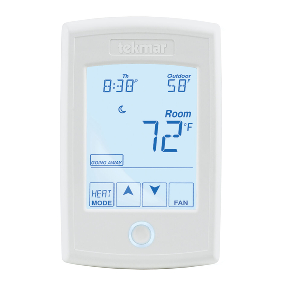
designed to operate one heating stage, one cooling stage, and a fan.
A Watts Water Technologies Company
®
Thermostat 554
®
Thermostat 554 is a communicating touchscreen thermostat
Features
•
tekmarNet
compatible
•
Touchscreen technology
•
Radiant floor heating
•
Programmable schedule
•
Network schedule master or
member
•
Optimum start
•
Air group master
•
Room temperature limiting
•
Temporary hold
•
2 auxiliary sensor inputs
•
Away scene key
1 of 44
554 _ D
Zoning
Replaces: New
®
communication
© 2015
554_D - 02/15
02/15
Advertisement
Table of Contents

Related Manuals for Tekmar tekmarNet 554


Summary of Contents for Tekmar tekmarNet 554
- Page 1 554 _ D 02/15 tekmarNet ® Thermostat 554 Zoning Replaces: New Installation & Operation Manual Introduction ® The tekmarNet Thermostat 554 is a communicating touchscreen thermostat designed to operate one heating stage, one cooling stage, and a fan. Features ® •...
-
Page 2: Table Of Contents
Table of Contents Important Safety Information ................3 Getting Started .....................4 Installation .........................4 Preparation ......................4 Removing the Thermostat Base ................5 Mounting the Thermostat Base ................5 Thermostat Wiring ....................6 Compatible Sensors .....................6 Testing the Thermostat Wiring ................7 Mounting the Thermostat ..................9 Switch Settings ......................9 User Interface ...................... -
Page 3: Important Safety Information
Important Safety Information It is your responsibility to ensure that this thermostat is safely installed according to all applicable codes and standards. tekmar is not responsible for damages resulting from improper installation and/or maintenance. This is a safety-alert symbol. The safety alert symbol is shown alone or used with a signal word (DANGER, WARNING, or CAUTION), a pictorial and/or a safety message to identify hazards. -
Page 4: Getting Started
Getting Started ® Congratulations on the purchase of your new tekmar thermostat. This manual will step through the complete installation, programming and sequence of operation for this control. At the back, there are tips for control and system troubleshooting. Installation... -
Page 5: Removing The Thermostat Base
To prevent the risk of personal injury and/or death, make sure power is not applied to the thermostat until it is fully installed and ready for final testing. All work must be done with power to the circuit being worked on turned off. -
Page 6: Thermostat Wiring
If a gang box is not used: • Feed the wiring through the large hole in the thermostat base. Thermostat Thermostat Base Stud • Mount the thermostat base Front directly to the wall. • Use screws in the screw holes to fasten the thermostat to the wall. -
Page 7: Testing The Thermostat Wiring
If the thermostat display continues to be off, or is cycling on and off, there may be a fault on the thermostat. If a fault is suspected, contact your tekmar sales representative for assistance. A Watts Water Technologies Company 7 of 44 ©... - Page 8 - - - - - - - - - - - - - - - - - - - - - - - - - - ® Testing tekmarNet 4 and Stand Alone Wiring Testing the Power 1. Remove the front cover from the thermostat. 2.
-
Page 9: Mounting The Thermostat
Mounting the Thermostat Push the thermostat front onto the thermostat base. Installation is now complete. Thermostat Base Thermostat Front Push Switch Settings tekmarNet Switch Thermostat 554 Settings One Stage Heat, One Stage Cool, One Fan Back of www.tekmarcontrols.com Thermostat Power: tN2 or 24 V (ac) ±10% 1.8 VA Relay: 24 V (ac) 2 A Designed and assembled in Canada Mmm YYYY... -
Page 10: User Interface
User Interface Home Screen Display Heat & Cool Adjust settings, Floor or the Time Outdoor temperature Adjust the Schedule Room Temperature Away Key Turn the Fan on Switch between Auto, Heat, Cool & Off Mode Return to the ‘Home’ Screen Home Adjust the from any menu... -
Page 11: Programmable Settings
Programmable Settings Programming Menus Press and hold the Home button for 3 seconds to enter the programming menus. The thermostat returns to the last programming menu previously used. Press and hold for 3 seconds to access the programming menus. - - - ---- - - - - - - - - - - - - - - - - - - - - - - - - - - - - - - - - - - Select a Programming Menu •... -
Page 12: Set Temp Menu
Set Temp Menu (1 of 4) Setting Display Room SET HEAT ROOM Set the room heating temperature for the event. Access Level: Installer, User Range: 40 to 95°F (4.5 to 35.0°C) Conditions: Always available. Default: 70°F (21.0°C) Room SET HEAT ROOM Set the room heating temperature for the event. - Page 13 Set Temp Menu (2 of 4) Setting Display WARM WEATHER SHUT DOWN Set the outdoor air temperature at which heating is suspended during the event. Range: CTRL (control), Access Level: Installer 40 to 100°F (4.5 to 38.0°C), OFF Conditions: An outdoor sensor must be available and Default: CTRL (with tN System Schedules are in use or Scenes is set to All or Guest.
- Page 14 Set Temp Menu (3 of 4) Setting Display COOL MAXIMUM ROOM LIMIT Set the maximum room cooling limit. Access Level: Installer Range: 50 to 100°F (10.0 to 38.0°C) Conditions: Always available. Default: 100°F (38.0°C) FLOOR MINIMUM Set the floor heating temperature while in the event.
-
Page 15: Set Temp Menu
Set Temp Menu (4 of 4) Setting Display Set the minimum percentage of time the fan should operate while in the event. This provides ventilation for the building. Each 10% is 6 minutes per hour. Access Level: Installer, User Range: Auto, 10 to 90%, ON Conditions: 10 to 90% available if Ventilation Mode is Default: Auto Set the minimum percentage of time the fan should... -
Page 16: Time Menu
Time Menu (1 of 1) Setting Display MINUTES Select the current time minutes. Access Level: Installer, User Range: 00 to 59 Conditions: Always available. Default: 00 HOURS Select the current time hours. Access Level: Installer, User Range: 12 AM to 11 PM or 00 to 23 Conditions: Always available. -
Page 17: Schedule Menu
Schedule Menu (1 of 2) The schedule menu can operate on a 24-hour or 7-day repeating schedule. When a 24-hour schedule is selected, “SuMoTuWeThFrSa” is shown on the top of the screen to show that the event time applies to all days of the week. When a 7-day schedule is selected, each individual day of the week is shown with the event time. -
Page 18: Schedule Menu
Schedule Menu (2 of 2) Setting Display SCHEDULE Select if the thermostat should change the temperature automatically using a programmable schedule. OFF = Programmable schedule is not used. Zone = Applies to this thermostat only. Master 1, 2, 3, 4 = In charge of one of four available network schedules. -
Page 19: Display Menu
Display Menu (1 of 1) Setting Display UNITS Select Fahrenheit or Celsius as the temperature units. Access Level: Installer, User Range: °F or °C Conditions: Always available. Default: °F BACKLIGHT Select how the display backlight operates. DIM = Dim when inactive, on when touched. ON = Always full brightness. -
Page 20: Scenes Menu
Scenes Menu (1 of 1) Setting Display SCENES Enable or disable the use of scenes (building overrides) on this thermostat. Access Level: Installer, User Range: NONE, AWAY, ALL, GUEST Conditions: Settings ALL and GUEST only available Default: NONE in Installer access level. SCENE 4 Select how the thermostat should respond to scene 4. -
Page 21: Monitor Menu
Monitor Menu (1 of 3) Setting Display ROOM AVERAGE Current room temperature. Displays the average if there are multiple room sensors. Range: -58 to 212°F Access Level: Installer (-50.0 to 100.0°C) Conditions: Sensor 1 or 2 is set to ROOM. Default: Not applicable. - Page 22 Monitor Menu (2 of 3) Setting Display SENSOR 2 The temperature measurement from the sensor 2 input wiring terminals. Range: -58 to 212°F Access Level: Installer (-50.0 to 100.0°C) Conditions: Sensor 2 is set to ROOM, FLOR, or OUT. Default: Not applicable. OUTDOOR HIGH The highest recorded outdoor air temperature measurement.
- Page 23 Monitor Menu (3 of 3) Setting Display FLOOR LOW The lowest recorded floor temperature measurement. Touch the number and the ENTER key to reset. Range: -76 to 149°F Access Level: Installer, User (-60.0 to 65.0°C) Conditions: Sensor 1 or 2 is set to FLOR. Default: Not applicable.
-
Page 24: Toolbox Menu
Toolbox Menu (1 of 2) Setting Display ACCESS LEVEL Selects the access level of the thermostat, which determines which menus and items are available. Access Level: Installer (INST), User, Limited (LTD), Secure Range: INST, USER, LTD, (SEC) Conditions: Adjustable only when thermostat switch setting Default: INST ®... -
Page 25: Toolbox Menu
2:01 to 2:24, 3:01 to 3:24 Conditions: tekmarNet ® 2 or 4 detected. Default: AUTO SOFTWARE AND TYPE VERSION Displays the software version and the tekmar type number. Access Level: Installer, User, Limited, Secure Range: 554 Conditions: Always available. Default: 554 DEVICE COUNT ®... - Page 26 Setup Menu (1 of 4) Setting Display SENSOR 1 Select the auxiliary sensor input 1 type. Range: OFF, ROOM, FLOR (floor), Access Level: Installer COIL, DUCT Conditions: Coil sensor option available when W TERMINAL is set to COIL. Duct sensor option available when W TERMINAL is Default: OFF set to FURN or COIL.
-
Page 27: Setup Menu
Setup Menu (2 of 4) Setting Display W THERMAL MOTOR Select whether the first stage of heat W operates a thermally actuated zone valve (wax actuator). When set to ON, there is a 3-minute delay before operating the pump and any heat sources. Access Level: Installer Range: OFF or ON ®... - Page 28 Setup Menu (3 of 4) Setting Display BASELOAD Select the level of radiant floor baseload heating. This warms the floor so that solar gain and/or air heating systems do not cause cold floors. Access Level: Installer Range: OFF, LOW, MED, HIGH ®...
- Page 29 Setup Menu (4 of 4) Setting Display FAN DELAY Select the time delay to allow the fan coil or furnace to warm up prior to activating the fan. This avoids blowing cold air. Range: NONE, 0:10 to 6:00 Access Level: Installer minutes Conditions: Sensor 1 is not set to COIL and W Default: 0:30 minutes...
-
Page 30: Sequence Of Operation
Sequence of Operation Heating Operation - ---- --- ---- -- - - - - - - - - - - - - - - - - - - - - - - - - - - - - - - - - - - Set Heat Temperature When using only a room temperature sensor, the thermostat operates the heating system to maintain the Set Heat Room temperature. -
Page 31: Cooling Operation
Cooling Operation ---- - - - - - ---- - - - - - - - - - - - - - - - - - - - - - - - - - - - - - - - - - - Set Cool Temperature The thermostat operates an air conditioner to provide cooling. -
Page 32: Fan Operation
--- -- - - - - - - - - - - - - - - - - - - - - - - - - - - - - - - - - - - Hydronic System Supply Pump ®... -
Page 33: Air Group Operation
Air Group Operation To prevent heating and cooling at the same time, this thermostat can operate with other thermostats on a tekmarNet system to form an air group. The 554 can be set up as the air group master. Other heat-only thermostats can be set up as an air group member. -
Page 34: Temperature Adjustment
Temperature Adjustment Permanent Adjustment ― No Schedule -- - -- - -- --- - -- - -- -- - -- - -- -- - -- - -- -- - When no programmable schedule is used, touch the up or down arrows to permanently set the “Set Heat Room”... -
Page 35: Programmable Schedules
Programmable Schedules Energy savings can be achieved by lowering the heating temperature and increasing the cooling temperature, for example, at night, or at other times when the building is unoccupied. When operating on a programmable schedule, a or a symbol is shown in the Home menu. -
Page 36: Scenes (System Override)
Scenes (System Override) Scenes provide an easy way to save energy, when building residents are on vacation, for example, or override a programmable schedule when plans change. Away Key - ---- -- -- -- - -- - - - - - - - - - - - - - - -- -- - -- - -- -- - -- - -- - -- -- - -- - -- -- - -- - -- -- This thermostat includes an Away Key to set the thermostat to quickly turn down the heating temperatures and increase the cooling temperatures on all thermostats and suspend heating the domestic hot water tank to maximize energy savings. -
Page 37: Secondary Temperature Display
- - - - - - - - - - - - - - - - - - - - - - - - - - - - - Recommendation on How to Use Scenes Deciding how to use scenes depends on the needs and lifestyle of the customer using the building. -
Page 38: Access Levels
Access Levels The thermostat Toolbox menu supports four access levels: Installer (INST), User (USER), Limited (LTD), and Secure (SEC). The access level can be adjusted when the thermostat is unlocked. There are two locations to lock the thermostat: 1. Locally on the thermostat using the Lock switch located in the wiring area. 2. -
Page 39: Troubleshooting
Troubleshooting Error Messages (1 of 4) Error Message Description SETUP MENU SAVE ERROR The thermostat failed to read the Setup menu settings from memory and has reloaded the factory default settings. The thermostat stops normal operation until all settings in the Setup menu are checked except to provide freeze protection. - Page 40 ® is connected to a tekmarNet system control, the thermostat continues to operate; otherwise operation stops. ® The error cannot be field repaired. Contact your tekmar sales representative for repair procedures. 40 of 44 A Watts Water Technologies Company © 2015...
- Page 41 ® The error cannot be field repaired. Contact your tekmar sales representative for repair procedures. SENSOR 1 OR 2 SHORT CIRCUIT ERROR Due to a short circuit, the thermostat is unable to read auxiliary Sensor 1 or 2.
- Page 42 Error Messages (4 of 4) Error Message Description SCHEDULE MASTER ERROR ® Two thermostats on the tekmarNet system have been set to the same Schedule Master number. The thermostat operates at the temperature settings while this error is present. To clear the error, select a different Schedule Master number, set a different Schedule Member number, set the Schedule to Zone, or set the Schedule to None.
-
Page 43: Technical Data
Temperature sensor NTC thermistor, 10 kΩ @ 77°F (25°C ±0.2°C) ß=3892 – Included None – Optional tekmar type # 070, 071, 072, 073, 076, 077, 079, 082, 083, 084 A Watts Water Technologies Company 43 of 44 © 2015 554_D - 02/15... -
Page 44: Limited Warranty And Product Return Procedure
Prod- uct was not installed in compliance with tekmar’s instructions and / or the local codes and ordinances; or if due to defective installation of the Product; or if the Product was not used in compliance with tekmar’s instructions.
Need help?
Do you have a question about the tekmarNet 554 and is the answer not in the manual?
Questions and answers