Tekmar tekmarNet Thermostat 532 Installation & Operation Manual
Hide thumbs
Also See for tekmarNet Thermostat 532:
- User manual (4 pages) ,
- Quick setup manual (12 pages)
Table of Contents
Advertisement
tekmarNet
Installation & Operation Manual
Introduction
The tekmarNet
®
stage hydronic heating systems. Simple up and down buttons and a display with
large type make this thermostat easy to read and use. It has two auxiliary sensor
inputs that can be assigned to measure room, floor, or outdoor temperature. An
optional floor sensor protects the floor from overheating and enhances comfort.
The 532 can be wired using 2 or 4 wires to connect to tekmarNet zoning controls,
or can be installed as a stand-alone thermostat using 3 wires.
A Watts Water Technologies Company
®
Thermostat 532
Thermostat 532 is a communicating thermostat designed for one
Features
•
tekmarNet communication
compatible
•
Radiant floor heating
•
Floor & air temperature control
•
Zone synchronization
•
Network schedule member
•
Optimum start
•
Away scene
•
Air group member
•
2 auxiliary sensor inputs
•
Backlight
•
Room temperature limiting
1 of 20
532 _ D
Zoning
Replaces: New
© 2015
532_D - 02/15
02/15
Advertisement
Table of Contents

Related Manuals for Tekmar tekmarNet Thermostat 532


Summary of Contents for Tekmar tekmarNet Thermostat 532
- Page 1 532 _ D 02/15 tekmarNet ® Thermostat 532 Zoning Replaces: New Installation & Operation Manual Introduction The tekmarNet ® Thermostat 532 is a communicating thermostat designed for one stage hydronic heating systems. Simple up and down buttons and a display with large type make this thermostat easy to read and use.
-
Page 2: Table Of Contents
Limited Warranty and Product Return Procedure ...........20 Getting Started ® Congratulations on the purchase of your new tekmar thermostat. This manual will step through the complete installation, programming and sequence of operation for this control. At the back, there are tips for control and system troubleshooting. -
Page 3: Important Safety Information
Important Safety Information It is your responsibility to ensure that this thermostat is safely installed according to all applicable codes and standards. tekmar is not responsible for damages resulting from improper installation and/or maintenance. This is a safety-alert symbol. The safety alert symbol is shown alone or used with a signal word (DANGER, WARNING, or CAUTION), a pictorial and/or a safety message to identify hazards. -
Page 4: Installation
-- ---- - ---- ---- --- -- - - - - - - - - - - - - - - - - - - - - - - - - - - - - - - - - - - Tools Required • tekmar or jeweller screwdriver • Drill (for wall anchor) •... -
Page 5: Mounting The Thermostat
Mounting The Thermostat To prevent the risk of personal injury and/or death, make sure power is not applied to the thermostat until it is fully installed and ready for final testing. All work must be done with power to the circuit being worked on turned off. -
Page 6: Thermostat Wiring
Thermostat Wiring - - - - - - - - - - - - - - -- - -- - - - - -- - - -- - -- - - - - - - - - - - - - - - - - - - - - - - - - - - - - - - - - tekmarNet ®... -
Page 7: Outdoor Sensor
Thermostat Wiring - -- - - -- - - - ----- - - - - - - - - - - - - - - - - - - - - - - -- -- - -- -- - --- - - - - ----- - ----- - - - - --- - - - - - - - - - - - - - - - - - - - - - - - - - - - - - - - - - - Switching Relay Optional... -
Page 8: Testing The Thermostat Wiring
If the thermostat display does not turn on after 20 seconds, try moving the thermostat tN2 wire connections to another zone on the tN2 Wiring Center or tN2 Zone Manager. If the thermostat display does not power on, contact your tekmar sales representative for assistance. -
Page 9: Switch Settings
Switch Settings The switch settings are located on the rear of thermostat face. Switch Position Action SETBACK The thermostat follows a programmable setback schedule as a schedule member if available. Requires the installation of a Thermostat 552, 553, 554, 557 or a Timer 033 to use this feature. -
Page 10: User Interface
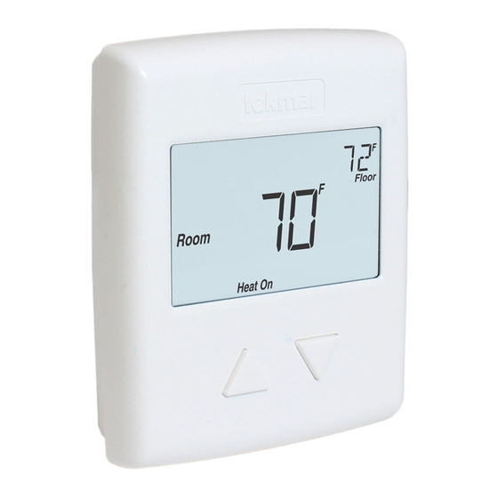
User Interface Home Screen Outdoor Away WWSD Room MINMAX Mode Floor Heat On Symbols Description HEAT ON WWSD Heat is turned on. Warm Weather Shut Down. MODE OFF WARNING SYMBOL The heating system is off. Indicates an error is present. SCENE AWAY Operating at the occupied Operating at Away... -
Page 11: Sequence Of Operation
Sequence of Operation Heating Operation To change the heat temperature setting, push the button to select a preferred temperature setting. The Heat On symbol is shown on the display when the thermostat is heating. The heat can cycle on and off within +/- 1.5°F (1°C) of the temperature setting. The floor and air heating can be shut off by holding the button until Set Room is Off. - Page 12 - - - - - - - - - - - - - - - - - -- - - - - -- - - -- - -- - - - - --- - - - - -- - - - - - - - - - - - - - - - - - - - - - - - - - - - - - - - - - - - Room Minimum and Maximum Room Minimum and Maximum temperature settings are available in the Setup menu.
-
Page 13: Air Group Operation
Air Group Operation Air Group In order to prevent heating and cooling at the same time, this thermostat can operate together with other thermostats on a tekmarNet system to form an air group. In an air group, a heat-cool thermostat is assigned as the air group master. -
Page 14: Scenes (System Override)
Scenes (System Override) Scenes provide an easy way to save energy while away on vacation, or override a ® pre-set schedule when plans change. tekmarNet devices such as a User Switch 479 provide scene adjustment. This thermostat responds to the following scenes: Scene Display Room Temperature Setting... -
Page 15: Programmable Settings
Programmable Settings Setting Range Default The following settings are available when the thermostat is locked or unlocked. Press the buttons together for 3 seconds to enter and advance to the next setting. MODE Heat, Off Heat Select heat or off. SET ROOM 40 to 95°F 70°F... - Page 16 Setting Range Default SCHEDULE The thermostat can follow a shared network schedule. 1 to 4 Select to follow either schedule master 1, 2, 3 or 4. Requires tekmarNet. The following additional settings are available when the thermostat is unlocked. SET LIMIT ROOM MAX 40 to 95°F 95°F Set the max room temperature limit while in the oc-...
-
Page 17: Troubleshooting
Troubleshooting Error Messages Error Message Description SETUP MENU SAVE ERROR The thermostat failed to read the programmable settings from memory and has reloaded the factory default settings. The thermostat operates on the factory defaults settings to ensure the building does not freeze. To clear the error, set the switch settings to unlock and go through all the settings in the Programmable Setting menu. - Page 18 The built-in air temperature sensor has an open circuit fault. Do not confuse this error with the auxiliary room sensor short circuit error. Room This error cannot be field repaired. Contact your wholesaler or tekmar sales representative for details on repair procedures. ROOM SENSOR SHORT CIRCUIT ERROR The built-in air temperature sensor has a short circuit fault.
-
Page 19: Technical Data
24 V (ac/dc), 2 A, Class 2 circuits Sensor NTC thermistor, 10 kΩ @ 77°F (25°C ±0.2°C) ß=3892 – Included None – Optional tekmar type # 070, 072, 073, 076, 077, 079, 084 A Watts Water Technologies Company 19 of 20 © 2015 532_D - 02/15... -
Page 20: Limited Warranty And Product Return Procedure
Prod- uct was not installed in compliance with tekmar’s instructions and / or the local codes and ordinances; or if due to defective installation of the Product; or if the Product was not used in compliance with tekmar’s instructions.
Need help?
Do you have a question about the tekmarNet Thermostat 532 and is the answer not in the manual?
Questions and answers