Tekmar tekmarNet 552 Installation & Operation Manual
Hide thumbs
Also See for tekmarNet 552:
- User manual (13 pages) ,
- Quick setup manual (13 pages) ,
- Installation & operation manual (44 pages)
Table of Contents
Advertisement
tekmarNet
Installation & Operation Manual
Introduction
The tekmarNet
®
provides operation for:
•
One Stage Heat
®
Thermostat 552
Thermostat 552
Features
•
Touchscreen
•
Bright Backlight
•
tekmarNet
•
Outdoor Temperature Display
•
Floor Temperature Display
•
7-Day, 4 Event Programmable
Schedule
•
Optimum Start
•
Scenes
•
Away Key
•
Air Group Member
•
Freeze Protection
•
Exercise Pump or Valves
•
Zone Synchronization
•
Floor Cooling Support
•
Two Auxiliary Sensor Inputs
Benefi ts
•
Simple to Use
•
Increased Comfort Through
Precise Temperature Control
•
Conserves Energy
•
Convenience Through Internet
Connectivity
•
Warm Radiant Floors
•
Protects Radiant Floors From
Over Heating
1 of 40
D552
Zoning
Replaces: New
®
Communication
© 2011
D 552 - 08/11
08/11
Advertisement
Table of Contents
Troubleshooting

Related Manuals for Tekmar tekmarNet 552


Summary of Contents for Tekmar tekmarNet 552
- Page 1 Benefi ts • Simple to Use • Increased Comfort Through Precise Temperature Control • Conserves Energy • Convenience Through Internet Connectivity • Warm Radiant Floors • Protects Radiant Floors From Over Heating 1 of 40 © 2011 D 552 - 08/11...
-
Page 2: Table Of Contents
Scenes Menu ......17 Getting Started Congratulations on the purchase of your new tekmar thermostat. This manual will step through the complete installation, programming and sequence of operation for this control. At the back, there are tips for control and system troubleshooting. -
Page 3: Preparation
Locate the tab on the bottom of the thermostat. • Push the tab with either your thumb or with a screwdriver. • Lift the thermostat front away from the thermostat’s base. 3 of 40 © 2011 D 552 - 08/11... -
Page 4: Mounting The Thermostat Base
Stand Alone - Simple 3 wire connection to a 24 V (ac) transformer and zone valve. Stand Alone - Simple 3 wire connection to a switching relay or zone valve control. © 2011 D 552 - 08/11 4 of 40... - Page 5 Wiring - Stand Alone to Transformer and Zone Valve Install field jumper Zone Valve Optional Sensor 1 wire R to Rh Optional Sensor 2 No Power Rh W1 24 V (ac) transformer 5 of 40 © 2011 D 552 - 08/11...
-
Page 6: Testing The Thermostat Wiring
If the thermostat display continues to be off, or is cycling on and off, there may be a fault on the thermostat. If a fault is suspected, contact your tekmar sales representative for assistance. © 2011 D 552 - 08/11... - Page 7 Use an electrical meter to measure for continuity. • If there is no continuity, there is an open circuit fault along the wires. It is recommended to replace the tN4 bus wires. 7 of 40 © 2011 D 552 - 08/11...
-
Page 8: Mounting The Thermostat
Note: tekmarNet ® system controls include a Global Lock that locks all connected thermostats. Set the tekmarNet ® system control to unlock to allow access level adjustment on all connected thermostats. © 2011 D 552 - 08/11 8 of 40... -
Page 9: User Interface
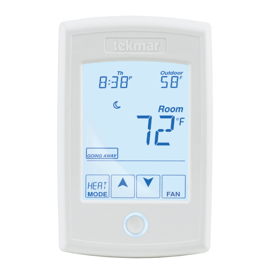
User Interface Home Screen The touchscreen of the 552 provides one touch access to these settings. Display the Adjust Floor or Outdoor the Time. temperature. Adjust the Schedule. Room Temperature. Away Key. Adjust the Temperature. Turn the Home Button. Heat on Return to the ‘Home’... -
Page 10: Programmable Settings
To return to the parent menu after changing a setting, press and release the home button. • To return to the home screen, press and release the home button twice or wait 30 seconds to automatically return to the home screen. © 2011 D 552 - 08/11 10 of 40... -
Page 11: Set Temp Menu
Floor event. Access Level: Installer, User Range: 40 to 122°F (4.5 to 50.0°C) Conditions: Room Sensor set to OFF and Sensor Default: 72°F (22.0°C) 1 or Sensor 2 set to Floor. 11 of 40 © 2011 D 552 - 08/11... - Page 12 Room Sensor set to ON, or Room Sensor set to OFF while Sensor 1 or 2 is set to Room, Default: OFF Schedules are in use or Scenes are set to All or Guest. © 2011 D 552 - 08/11 12 of 40...
-
Page 13: Time Menu
Select the current day of the week. Range: Sunday, Monday, Tuesday, Access Level: Installer, User Wednesday, Thursday, Friday, Saturday Conditions: Schedule is used or Clock is set to ON. Default: Sunday 13 of 40 © 2011 D 552 - 08/11... -
Page 14: Time Menu
Access Level: Installer, User Range: OFF or ON Conditions: The time is always shown when a schedule is used and the clock setting option is no Default: OFF longer available. © 2011 D 552 - 08/11 14 of 40... -
Page 15: Schedule Menu
Access Level: Installer, User or 00:00 to 23:50, SKIP Conditions: Schedule setting is set to Zone or Default: 10:00 PM Master 1, 2, 3, 4 and Event/Day is set to 4. 15 of 40 © 2011 D 552 - 08/11... -
Page 16: Display Menu
Default: ON Display Menu (1 of 2) Setting Display UNITS Select Fahrenheit or Celsius as the temperature units. Access Level: Installer, User Range: °F or °C Conditions: Always available. Default: °F © 2011 D 552 - 08/11 16 of 40... -
Page 17: Scenes Menu
Select if scenes and time clock are shared when ® connected to a tekmarNet system. OFF = Send and receive messages. ON = Receive messages only. Access Level: Installer Range: OFF or ON Conditions: Always available. Default: OFF 17 of 40 © 2011 D 552 - 08/11... -
Page 18: Monitor Menu
The temperature measurement from the sensor 2 input wiring terminals. Range: -22 to 266°F (-30.0 to Access Level: Installer 130.0°C) Conditions: Setup menu setting SENSOR 2 is set Default: Not applicable. to ROOM, FLOR, or OUT. © 2011 D 552 - 08/11 18 of 40... - Page 19 Touch the number and touch the ENTER key to reset. Range: -76 to 149°F (-60.0 to Access Level: Installer, User 65.0°C) Conditions: Setup menu setting SENSOR 1 or 2 is Range: Not applicable. set to FLOR. 19 of 40 © 2011 D 552 - 08/11...
-
Page 20: Toolbox Menu
Toggles between “Status Info” and the current status. ® Override W1 = The tekmarNet system control is either forcing the W1 relay on or off. Cooling Floor = Floor cooling is in effect. © 2011 D 552 - 08/11 20 of 40... - Page 21 Conditions: tekmarNet ® 2 or tekmarNet ® Default: AUTO communication detected. SOFTWARE AND TYPE VERSION Displays the software version and the tekmar type number. Access Level: Installer, User, Limited, Secure Range: 552 Conditions: Always available. Default: 552 21 of 40 ©...
-
Page 22: Troubleshooting
30 days. Touch Enter to manually clear the error code. Range: See Troubleshooting Access Level: Installer section Conditions: An error must have occurred in order to Default: Not applicable view in the error history. © 2011 D 552 - 08/11 22 of 40... -
Page 23: Setup Menu
Range: OFF or ON ® Conditions: Only available when a tekmarNet system control is connected and the Setup menu Default: ON setting W1 TERM is set to CTRL, HRF1, HRF2, CONV, or COIL. 23 of 40 © 2011 D 552 - 08/11... - Page 24 Select if the thermostat is a member of an air group or cooling group. Access Level: Installer Range: NONE, 1 to 16 Conditions: The thermostat must be connected to Default: NONE ® other thermostats using tekmarNet © 2011 D 552 - 08/11 24 of 40...
-
Page 25: Sequence Of Operation
This is also useful in areas that experience large solar gains through windows. The radiant baseload is automatically shut off in the summer by the warm weather shut down feature. 25 of 40 © 2011 D 552 - 08/11... -
Page 26: Radiant Floor Cooling Operation
Set Heat temperature plus 3°F (Set Heat+1.5°C) or reaches a minimum temperature of 74°F. If only a floor sensor is installed, the floor cooling setpoint is 67°F (19.5°C). © 2011 D 552 - 08/11 26 of 40... -
Page 27: Air Group Operation
When connected to a tekmarNet system, adjustment of the time on one thermostat updates all connected thermostats. This option can be disabled by selecting the Local Network Group setting to be On. 27 of 40 © 2011 D 552 - 08/11... -
Page 28: Temperature Adjustment
Cancel the down arrow displays temporary ‘TEMPORARY HOLD’. hold. Use the Up or Down ‘HOLD’ is displayed while the arrow to select a thermostat is operating at the temperature. temporary hold temperature. © 2011 D 552 - 08/11 28 of 40... -
Page 29: Programmable Schedules
Optimum Start to predict the heat up rate of the room. When Optimum Start is set to On, the heating is started in advance to allow the room to reach the Set Room temperature at the time set in the programmable schedule. 29 of 40 © 2011 D 552 - 08/11... -
Page 30: Scenes (System Override)
Scene 1 Scene 1 or Schedule or Schedule Temporary Scene 1 Scene 1 Permanent 3 Hours Temporary Scene 1 Scene 1 Permanent 4 Hours Temporary Scene 1 Scene 1 Permanent 8 Hours © 2011 D 552 - 08/11 30 of 40... -
Page 31: Secondary Temperature Display
® system that includes an outdoor sensor. The reading of the outdoor sensor connected directly to the thermostat takes precedence over any outdoor sensor reading available on the tekmarNet ® system. 31 of 40 © 2011 D 552 - 08/11... -
Page 32: Access Levels
Section K Screen Clean Menu Entering the Screen Clean menu gives you 30 seconds to clean the thermostat and display with a moist cloth. Do not use solvents to clean the thermostat. © 2011 D 552 - 08/11 32 of 40... -
Page 33: Troubleshooting
The thermostat continues to operate normally while displaying this error. To clear the error, set the access level to Installer and check all settings in the Time menu. 33 of 40 © 2011 D 552 - 08/11... - Page 34 More than 24 devices (thermostats or setpoint controls) have ® been connected to the tekmarNet communication bus. To clear the error, remove and relocate devices to other available buses until the device count is 24 or less. © 2011 D 552 - 08/11 34 of 40...
- Page 35 ® The error cannot be field repaired. Contact your tekmar sales representative for repair procedures. ROOM SENSOR OPEN CIRCUIT ERROR Due to an open circuit, the thermostat is unable to read the built- in room temperature sensor.
- Page 36 To clear the error, select a different Schedule Member number, set the Schedule to Zone, or set the Schedule to None. © 2011 D 552 - 08/11 36 of 40...
-
Page 37: Error Messages
3 bus with this tekmarNet address. ERROR AT SYSTEM CONTROL ® There is an error on the tekmarNet system control connected ® to the tekmarNet system and not on this thermostat. 37 of 40 © 2011 D 552 - 08/11... -
Page 38: Frequently Asked Questions
If required, the floor minimum can be adjusted in the Set Temp menu. temperature Flashing Floor cooling is in effect. Locate the heat-cool thermostat to set the cooling temperature. © 2011 D 552 - 08/11 38 of 40... -
Page 39: Job Record
24 V (ac) 2 A Sensors: NTC thermistor, 10 kΩ @ 77°F (25°C ±0.2°C) ß=3892 – Included None – Optional tekmar type # 070, 071, 072, 073, 076, 077, 078, 079, 082, 084 39 of 40 © 2011 D 552 - 08/11... -
Page 40: Limited Warranty And Product Return Procedure
(24) months from the production date. The liability of tekmar under the Limited Warranty shall be limited to, at tekmar’s sole discretion: the cost of parts and labor provided by tekmar to repair defects in materials and / or workmanship of the defective product; or to the exchange of the defective product for a warranty replacement product;...
Need help?
Do you have a question about the tekmarNet 552 and is the answer not in the manual?
Questions and answers