Emerson Liebert GXT3 Series User Manual
Ups 120v/208v 500va-3000va
Hide thumbs
Also See for Liebert GXT3 Series:
- User manual (46 pages) ,
- User manual (33 pages) ,
- User manual (44 pages)

Related Manuals for Emerson Liebert GXT3 Series


Summary of Contents for Emerson Liebert GXT3 Series
- Page 1 AC Power For Business-Critical Continuity™ Liebert GXT3 UPS 120V/208V 500VA-3000VA ® ™ User Manual...
-
Page 3: Table Of Contents
TABLE OF CONTENTS ..........1 MPORTANT AFETY RECAUTIONS... - Page 4 ............22 PERATION Startup Checklist for the Liebert GXT3 .
- Page 5 FIGURES Figure 1 Liebert GXT3 rack/tower models—front view ......... . 5 Figure 2 Liebert GXT3 minitower—front view .
-
Page 7: Important Safety Precautions
UPS if the front panel indications are not in accordance with these operating instructions or if the UPS performance alters in use. Refer all faults to your local dealer, Emerson Network Power rep- resentative or Emerson Network Power Channel Support. - Page 8 The Liebert GXT3 series complies with the requirements of EMC Directive 2004/108/EC and the pub- lished technical standards. Continued compliance requires installation in accordance with these instructions and use of accessories approved by Emerson.
-
Page 9: Glossary Of Symbols
LOSSARY OF YMBOLS Risk of electrical shock Indicates caution followed by important instructions AC input AC output Requests the user to consult the manual Indicates the unit contains a valve-regulated lead acid battery PbH2SO4 Recycle DC voltage Equipment grounding conductor Bonded to ground AC voltage ON/Alarm Silence/Battery Test... -
Page 10: Product Description
Product Description RODUCT ESCRIPTION The Liebert GXT3 is a compact, online uninterruptible power system (UPS) that continuously condi- tions and regulates its output voltage. The Liebert GXT3 is designed to supply microcomputers and other sensitive equipment with clean sine wave input power. Upon generation, AC power is clean and stable. -
Page 11: Rear Panel Features
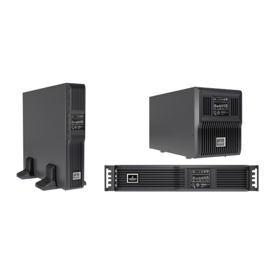
Product Description Figure 1 Liebert GXT3 rack/tower models—front view Ventilation Slots Operation and Display Panel The Liebert GXT3-1000MT120 has the same controls and features in a minitower arrangement (see Figure 2). Figure 2 Liebert GXT3 minitower—front view Operation and Display Panel Ventilation Slots 1.3.2 Rear Panel Features... -
Page 12: Figure 3 Liebert Gxt3 120V Rack/Tower Models-Rear Panel Components
Product Description Figure 3 Liebert GXT3 120V rack/tower models—rear panel components 500VA, 700VA, 1000VA, 1500VA Models Input Power Plug and Cable 5-15P Input Circuit USB Port Breaker Liebert IntelliSlot Port Output Receptacles, 5-15R External Terminal Block Battery Communication Cooling Connector 2000VA Model Input Power Plug and Cable, 5-20P... -
Page 13: Figure 4 Liebert Gxt3 208V Rack/Tower Models-Rear Panel Components
Product Description Figure 4 Liebert GXT3 208V rack/tower models—rear panel components 3000VA Model Input Power Plug and Cable, L6-20P Output Output Circuit Receptacle, Input Circuit Breakers USB Port L6-20R Breaker Liebert IntelliSlot Port External Terminal Block Battery Cooling Communication Connector Output Receptacles, L6-15R... -
Page 14: Major Components
Product Description Major Components The operating principle of the UPS is illustrated in Figure 6. Figure 6 Operating principle diagram Input Output Dynamic Bypass TVSS & EMI/ Rectifier / Inverter RFI Filters DC-to-DC Converter Battery Battery Charger L2/N L2/N The UPS is composed of utility input, TVSS and EMI/RFI filters, rectifier/PFC, inverter, battery char- ger, DC-to-DC converter, battery, dynamic bypass and UPS output. -
Page 15: Operating Mode
Product Description Battery Charger The battery charger utilizes energy from the utility power and precisely regulates it to continuously float charge the batteries. The batteries are being charged whenever the Liebert GXT3 is plugged in, even when the UPS is not turned On. DC-to-DC Converter The DC-to-DC converter raises the DC voltage from the battery to the optimum operating voltage for the inverter. -
Page 16: Battery Mode
Product Description 1.5.3 Battery Mode The Liebert GXT3 enters Battery Mode when utility power fails or is outside acceptable values. The battery system supplies power through the DC-to-DC converter to the inverter to generate clean AC power for the connected loads. When the Liebert GXT3 enters Battery Mode, the UPS sounds a half-second beep at 10-second inter- vals. -
Page 17: Installation
• Inspect the UPS for shipping damage. If any shipping damage is found, report it to the carrier and your local dealer or your Emerson representative immediately. • Check the accessories included in packaging list. If there is any discrepancy, contact your local dealer or your Emerson representative immediately. -
Page 18: Tower Installation
Installation 2.4.1 Tower Installation To install the Liebert GXT3 as a tower: 1. Take out support bases from the accessories (see Figure 7). Figure 7 Support bases Spacers Connectors Support Bases 2. If optional Liebert external battery cabinets will be connected to the Liebert GXT3, take out the spacers shipped with the battery cabinet. -
Page 19: Figure 10 Tower Installation
Installation Figure 10 Tower installation Liebert GXT3 UPS and Liebert GXT3 UPS External Battery Cabinet Operation and Display Panel Rotated for Tower Operation Support Bases Support Bases... -
Page 20: Rack Installation
UPS. They are used to move the UPS into and out of the rack and attach the UPS to the rack. • Mounting hardware and slide rails are sold separately. Contact your local Emerson representative for these options and any assistance. -
Page 21: Figure 13 Installing Front Member Of Each Bracket Assembly
Installation 5. Extend the bracket assembly by sliding the front member forward until it touches the rack’s front vertical rails (adjustable length: 18 to 32 inches [457-813mm]). Use two M5 screws to fix each front member onto the front vertical rails through the installation holes. Make sure that bracket assemblies are at the same mounting height on all four rack rails, as shown in Figure 13. -
Page 22: Figure 16 Installing Ears
Installation Figure 16 Installing ears Liebert GXT3 UPS Ear, 2 pieces M4 Screw , 8 pieces 9. Insert the UPS, with inner members attached, into bracket assemblies by inserting top and bottom edges of inner members into the top and bottom, curved tracks of front members and sliding the UPS into rack, as shown in Figure 17. -
Page 23: Cable Connection
Prepare an input power supply that is properly protected by a circuit breaker in accordance with national and local electrical codes. The wall receptacle must be grounded. Emerson recommends installing an upstream circuit breaker of the same series as the Liebert GXT3’s input circuit breaker. -
Page 24: Connecting Communication Cables
Installation Connecting Communication Cables Communication cable connection includes: USB and option card cables. 2.6.1 Connecting USB Communication Cables 1. Take the USB communication cables out of the accessories box. 2. Insert one end of the USB communication cable to the USB port on the rear panel of the Liebert GXT3 (see Figures 3 and 5). -
Page 25: Controls And
Controls and Indicators ONTROLS AND NDICATORS The operation and display panel, shown in Figure 18, is on the front panel of the Liebert GXT3 (see Figures 1 and 2). Figure 18 Operation and display panel Battery Level Indicators Load Level Indicators Fault Indicator Bypass Indicator AC Input Indicator... -
Page 26: Indicators
Controls and Indicators Indicators The operation and display panel has seven indicators (see Figure 18). The indicators can be divided into two groups according to the applications: level indicators and UPS status indicators. 3.2.1 Level Indicators Battery Level Indicators The battery level indicator is composed of five sets of LED bars that illuminate and flash to indicate the battery capacity level. -
Page 27: Ups Status Indicators
Controls and Indicators 3.2.2 UPS Status Indicators UPS status is indicated by five symbols: fault indicator, AC input indicator, battery indicator, inverter indicator and bypass indicator. Table 5 shows the symbols and their meaning. Table 5 UPS status indicators UPS Status Indicator Icon Color... -
Page 28: Operation
• If none of the five Battery LEDs illuminate during the manual battery test a second time, replace the batteries, and contact your local Emerson representative or Emerson Channel Support. Manual Bypass Press the Standby/Manual Bypass button once while the UPS is in utility (AC) mode, the UPS will transfer the connected loads to the internal bypass. -
Page 29: Disconnecting Input Power From The Liebert Gxt3
Operation Disconnecting Input Power from the Liebert GXT3 1. Once the UPS has been shut down as detailed in 4.5 - Shut Down the Liebert GXT3, disconnect the input cable plug. 2. Wait 30 seconds and verify that all indicators have turned Off and the fan has stopped; this indicates that the power-off is complete. -
Page 30: Communication
Communication OMMUNICATION This chapter describes UPS communication over the three types of communication connections on the rear of the Liebert GXT3: • Liebert IntelliSlot port • USB port (standard B-type) • Terminal Block Communication CAUTION To maintain safety (SELV) barriers and for electromagnetic compatibility, signal cables should be segregated and run separate from all other power cables. -
Page 31: Usb Port Communication
Communication USB Port Communication The standard B-type USB port is used to connect the UPS and network server or other computer sys- tem using Liebert MultiLink. Configuration program can be completed through the communication port. 5.2.1 Configuration Program Accessing the Configuration Program via USB is a new feature of the Liebert GXT3. For most users, the factory default settings will be adequate. -
Page 32: Terminal Block Communication
Communication Terminal Block Communication The Terminal Block includes eight pins, as shown in Figure 21. Figure 21 Terminal block layout Any Mode Shut Down Battery Mode Shut Down Battery Mode Low Battery 5.3.1 Any-Mode Shutdown The purpose of Any Mode Shutdown is to shut down the UPS output by turning Off the rectifier, inverter and bypass so that there is no power to the loads. -
Page 33: Battery Mode Shutdown
Communication 5.3.2 Battery Mode Shutdown Battery Mode Shutdown permits shutting down the UPS by turning Off the rectifier, inverter and bypass so that there is no power to the load when the UPS is On Battery. Battery Mode Shutdown can be performed locally or remotely: •... -
Page 34: Maintenance
The Liebert GXT3 is designed to allow the user to replace the internal battery pack safely. Read the safety cautions before proceeding. Contact your local dealer or Emerson representative to obtain the part number and pricing of the appropriate replacement battery pack. -
Page 35: Battery Charging
The Liebert GXT3 charges the batteries continuously when it is connected to the utility input power. If the Liebert GXT3 will be stored for a long time, Emerson recommends connecting the UPS to input power for at least 24 hours every four to six months to ensure full recharge of the batteries. -
Page 36: Precautions
Channel Support. • Check if the battery is discharging: When the utility input is normal, the battery should not dis- charge. If the UPS is operating in Battery Mode, stop and contact your local Emerson representa- tive or Emerson Channel Support. -
Page 37: Troubleshooting
Troubleshooting ROUBLESHOOTING This section indicates various UPS symptoms a user may encounter and troubleshooting steps in the event the UPS develops a problem. Use the following information to determine whether external fac- tors caused the problem and how to remedy the situation. UPS Symptoms The following symptoms indicate the Liebert GXT3 has malfunctions. -
Page 38: Audible Alarm
Bypass reminder 1-second beep every 2 minutes Troubleshooting In the event of an issue with the UPS, refer to Table 9 to determine the cause and solution. If the issue persists, contact Emerson Channel Support. Table 9 Troubleshooting Problem Cause Solution Ensure UPS is Off. - Page 39 When reporting a UPS issue to Emerson, include the UPS model and serial number. These are on the top panel of the Liebert GXT3.
-
Page 40: Battery Cabinet
Battery Cabinet ATTERY ABINET Optional battery cabinets are available for the Liebert GXT3. The battery port and input breaker are on the battery cabinet’s rear panel, as shown in Figure 26. For battery cabinet specifications, refer to Table 12. For battery run times, refer to Table 14. Figure 26 Battery cabinet Input Breaker Battery Ports... -
Page 41: Specifications
Specifications PECIFICATIONS Table 10 Specifications of GXT3-500RT120 - GXT3-1000RT120 and GXT3-1000MT120 UPS Product Model GXT3-500RT120 GXT3-700RT120 GXT3-1000RT120 GXT3-1000MT120 Parameters (500VA/450W) (700VA/630W) (1000VA/900W) (1000VA/900W) Dimensions, D × W × H, in. (mm) 19.7 x 16.9 x 3.4 15.4 x 6.9 x 8.9 Unit (497 ×... -
Page 42: Table 11 Specifications Of Gxt3-1500Rt120 - Gxt3-3000Rt120 And Gxt3-3000Rt208 Ups
Specifications Table 11 Specifications of GXT3-1500RT120 - GXT3-3000RT120 and GXT3-3000RT208 UPS Product Model GXT3-1500RT120 GXT3-2000RT120 GXT3-3000RT120 GXT3-3000RT208 Parameters (1500VA/1350W) (2000VA/1800W) (3000VA/2700W) (3000VA/2700W) Dimensions, D × W × H, in. (mm) 19.7 x 16.9 x 3.4 23.7 x 16.9 x 3.4 Unit (497 ×... -
Page 43: Table 12 Operating Temperature Parameters
Specifications Table 12 Battery cabinet specifications Model Number Parameter GXT3-48VBATT GXT3-72VBATT GXT3-500RT120, GXT3-700RT120 GXT3-1000RT120, GXT3-1000MT120 GXT3-3000RT120 Used w/UPS Model GXT3-1500RT120, GXT3-2000RT120 GXT3-3000RT208 Dimensions, D × W × H, in (mm) 19.7 x 16.9 x 3.3 23.7 x 16.9 x 3.3 Unit (497 ×... -
Page 44: Table 14 Battery Run Times
Specifications Table 14 Battery run times Run Time, Minutes, for Load, W 100% Load Number of Model Batteries 1000 1200 1400 1600 1800 2000 2500 Min. 500VA — — — — — — — — — 700VA — — — —... -
Page 45: Product Warranty Registration
To register for warranty protection, visit the Quick Links section of the Liebert Web site at: http://www.liebert.com Click on Product Warranty Registration and fill in the form. If you have any questions, contact Emerson Channel Support at: North America: 800-222-5877 Outside North America: 00-800-1155-4499... - Page 46 Specifications...
- Page 48 Racks & Integrated Cabinets Connectivity Embedded Power Power Switching & Controls Services DC Power Monitoring Precision Cooling Surge Protection Business-Critical Continuity, Emerson Network Power and the Emerson Network Power logo are trademarks and service marks of Emerson Electric Co. ©2009 Emerson Electric Co.
Need help?
Do you have a question about the Liebert GXT3 Series and is the answer not in the manual?
Questions and answers
I need technical service to help troubleshoot and issue
Contact your local dealer or your Emerson representative for technical service and troubleshooting of the Liebert GXT3 Series.
This answer is automatically generated