Emerson Liebert GXT3 User Manual
230v 700va-3000va
Hide thumbs
Also See for Liebert GXT3:
- User manual (48 pages) ,
- User manual (44 pages) ,
- User manual (33 pages)

Related Manuals for Emerson Liebert GXT3


Summary of Contents for Emerson Liebert GXT3
- Page 1 AC Power For Business-Critical Continuity™ ® ™ Liebert GXT3 UPS 230V 700VA-3000VA User Manual...
-
Page 3: Table Of Contents
Startup Checklist for the Liebert GXT3 ........ - Page 4 ..........21 Disconnecting Input Power from the Liebert GXT3....... . 21 .
- Page 5 FIGURES Figure 1 Liebert GXT3-700RT230 - GXT3-3000RT230 UPS 5 Figure 2 Rear panel components, Liebert GXT3 230V 700VA, 1000VA and 1500VA models 5 Figure 3 Rear panel components, Liebert GXT3 230V 2000VA models 5 ® ™ Figure 4 Rear panel components, Liebert...
-
Page 7: Important Safety Precautions
This UPS is not intended for use with life support and other designated critical devices. Maximum load must not exceed that shown on the UPS rating label. This UPS is designed for data processing equipment. If uncertain, consult your local dealer or Emerson representative. - Page 8 Class A digital device. Operating this device in a residential area is likely to cause harmful interference that users must correct at their own expense. The Liebert GXT3 series complies with the requirements of EMC Directive 2004/108/EC and the published technical standards. Continued compliance requires installation in accordance with these instructions and use of accessories approved by Emerson.
-
Page 9: Glossary Of Symbols
LOSSARY OF YMBOLS Risk of electrical shock Indicates caution followed by important instructions AC input AC output Requests the user to consult the manual Indicates the unit contains a valve-regulated lead acid battery PbH2SO4 Recycle DC voltage Equipment grounding conductor Bonded to ground AC voltage ON/Alarm Silence/Battery Test... -
Page 10: Product Description
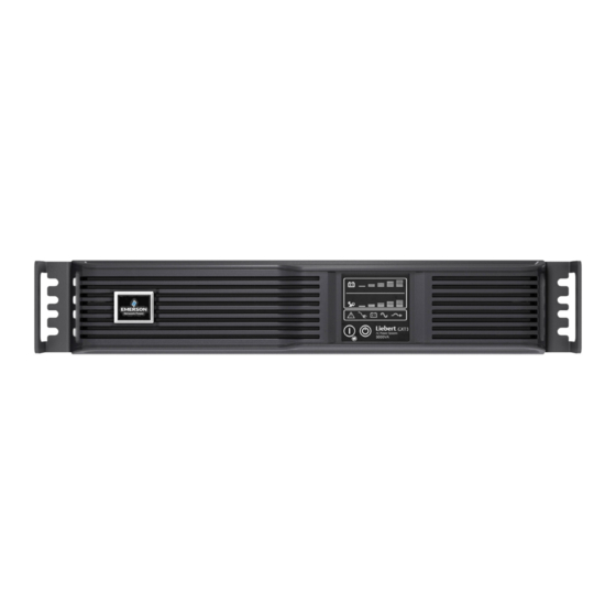
GXT3 is a compact, online uninterruptible power system (UPS) that continuously conditions and regulates its output voltage. The Liebert GXT3 is designed to supply microcomputers and other sensitive electronic equipment with clean sine wave input power, 700VA to 3000VA at 230V. -
Page 11: Appearance And Components
• Input circuit breaker ® • Liebert IntelliSlot • Communication terminal block • Input receptacle Figure 2 Rear panel components, Liebert GXT3 230V 700VA, 1000VA and 1500VA models Liebert IntelliSlot Port C14 Input Receptacle Input Circuit USB Port Breaker External Battery... -
Page 12: Major Components
DC-to-DC converter, battery, dynamic bypass and UPS output. Transient Voltage Surge Suppression (TVSS) and EMI/RFI Filters The Liebert GXT3 has surge protection and filters that protect the connected load from power surges and sags, electromagnetic interference (EMI) and radio frequency interference (RFI). These features can minimize any surges or interference present in the mains power. -
Page 13: Operating Mode
UPS. Inverter In normal operation, the Liebert GXT3’s inverter utilizes the DC output of the PFC circuit to produce precise, regulated sine wave AC power. When mains power fails, the inverter receives DC power from the battery through the DC-to DC converter. In either operation mode, the UPS inverter is online, continuously generating clean, precise, regulated AC output power. -
Page 14: Manual Bypass Mode
• Frequency Converter - 50Hz – Bypass Disabled • Frequency Converter - 60Hz – Bypass Disabled NOTE The default for all models of the Liebert GXT3 is “Auto Sensing - 50Hz or 60 Hz – Bypass Enabled.” CAUTION Do not touch the AC input receptacle when the UPS is operating. AC input voltages may still... -
Page 15: Installation
Installation Clearances Maintain a clearance of at least 100mm (4 inches) in the front and rear of the Liebert GXT3. Do not obstruct the air inlets on the front panel and rear panel of the UPS; blocking the air inlets reduces... -
Page 16: Mechanical Installation
The Liebert GXT3 may be installed as a tower or in a rack, depending on space and use considerations. The Liebert GXT3 may be used alone, as a single UPS, or with up to four battery cabinets. NOTE When installing the UPS or making input and output connections, comply with all relevant safety codes and standards. -
Page 17: Figure 8 Rotate The Operation And Display Panel
90 degrees clockwise, which provides upright viewing for users. 5. Place the Liebert GXT3 and any battery cabinets on the support bases. Each Liebert GXT3 needs four support bases, as shown in Figure 9. -
Page 18: Rack Installation
Bracket assembly Retaining latch Inner member 3. Determine the desired height and mounting position of the Liebert GXT3 inside the rack’s vertical rails. CAUTION Reduce risk of tipping the rack by installing the Liebert GXT3 in the lowest possible rack position. -
Page 19: Figure 11 Installing Rear Member Of Each Bracket Assembly
Installation Figure 11 Installing rear member of each bracket assembly Vertical pole M5 screw (4 pcs) Rear member Front member 5. Extend bracket assembly by sliding the front member forward until it touches the rack’s front vertical rails (adjustable length: 18 inches to 32 inches). 6. -
Page 20: Figure 14 Installing Inner Members
M4 screws provided in this kit. Make sure that the retaining latch is near the rear of the UPS, as shown in Figure 14. Figure 14 Installing inner members Liebert GXT3 UPS Inner Member Retaining Latch M4 screw , 8 pieces 9. -
Page 21: Cable Connection
GXT3-1000RT230 GXT3-1500RT230 GXT3-2000RT230 GXT3-3000RT230 1. Plug all loads into the output receptacles on the rear panel of the Liebert GXT3. NOTE 1. Do not overload any one output receptacle. 2. Output cable length should not exceed 10m (32.8 ft). 3. Plug the input receptacle of the Liebert GXT3 into the input power connection. -
Page 22: Connecting Communication Cables
IntelliSlot Card and Communication Cables 1. Remove the protective cover of the Liebert IntelliSlot port on the Liebert GXT3 and set it aside. 2. Insert the Liebert IntelliSlot card into the Liebert IntelliSlot port and secure it with screws. 3. To connect any cable associated with a Liebert IntelliSlot card, refer to the user manual provided with the card. -
Page 23: Operation And Display Panel
UPS is in Manual Bypass or Battery Mode. to the connected loads 1. If the bypass is not available due to voltage or frequency, pressing this button once will be ignored. 2. Perform all necessary shutdown procedures on connected loads before turning Off the Liebert GXT3. -
Page 24: Indicators
Operation and Display Panel Indicators The operation and display panel has seven indicators (see Figure 16). The indicators can be divided into two groups according to their applications: level indicators and UPS status indicators. 3.2.1 Level Indicators Battery Level Indicators The battery level indicator is composed of five sets of LED bars that illuminate and flash to indicate ®... -
Page 25: Ups Status Indicators
Operation and Display Panel 3.2.2 UPS Status Indicators UPS status is indicated by five symbols: fault indicator, AC input indicator, battery indicator, inverter indicator and bypass indicator. Table 5 shows the symbols and their meanings. Table 5 UPS status indicators UPS Status Indicator Icon... -
Page 26: Operation
3. Once the inverter LED has been illuminated, turn On the connected loads. 4. Check the status indicators to determine whether the Liebert GXT3 is operating normally. 5. Check the load level indicators to verify that the connected load does not exceed the UPS’s rated capacity. -
Page 27: Shut Down The Liebert ® Gxt3
UPS will shut down about 30 seconds after the button is pressed. Power to the connected loads is now Off. Disconnecting Input Power from the Liebert GXT3 1. After the UPS has been shut down as detailed in 4.5 - Shut Down the Liebert® GXT3™, disconnect the input cable plug. -
Page 28: Communication
The Liebert IntelliSlot 485 Card is used to connect the UPS and a BMS. Follow instructions provided with the Liebert IntelliSlot card to configure Liebert MultiLink, the UPS or any additional ancillary product for the Liebert GXT3. These instructions are available at: multilink.liebert.com 5.1.1... -
Page 29: Usb Port Communication
The output voltage settings cannot be changed while the UPS is On and powering connected loads. NOTE Programming the output voltage of a 230V model of the Liebert GXT3 to 220V automatically derates the UPS to 96% of both the VA and Watt ratings (refer to 9.0 - Specifications for VA and Watt ratings). -
Page 30: Terminal Block Communication
Communication Terminal Block Communication The Terminal Block includes eight pins, as shown in Figure 20. Figure 20 Terminal Block Communication pin layout Any Mode Shut Down Battery Mode Shut Down Battery Mode Low Battery 5.3.1 Any Mode Shutdown The purpose of Any Mode Shutdown is to shut down the UPS output by turning Off the rectifier, inverter and static switch so that there is no power to the loads. -
Page 31: Battery Mode Shutdown
This timer cannot be stopped once triggered. If the mains power returns during this countdown, the Liebert GXT3 will still shut down and must remain shut down for 10 seconds. Whether the UPS turns back On when the power is restored depends on the auto-restart setting. -
Page 32: Maintenance
Maintenance AINTENANCE This section describes replacing the internal battery pack, precautions, checking the Liebert GXT3’s status and checking UPS functions. WARNING The battery can present a risk of electrical shock and high short circuit current. The following precautions should be observed before replacing the battery pack: •... -
Page 33: Battery Charging
If the Liebert GXT3 will be stored for a long time, Emerson recommends connecting the UPS to input power for at least 24 hours every four to six months to ensure full recharge of the batteries. -
Page 34: Precautions
Emerson Channel Support. • Check whether the battery is discharging. When the mains input is normal, the battery should not discharge. If the UPS is operating in Battery Mode, stop and contact your local Emerson rep- resentative or Emerson Channel Support. -
Page 35: Troubleshooting
Troubleshooting ROUBLESHOOTING This section indicates various UPS symptoms a user may encounter and provides a troubleshooting guide in the event the UPS develops a problem. Use the following information to determine whether external factors caused the problem and how to remedy the situation. UPS Symptoms ®... -
Page 36: Audible Alarm
Check load level indicator and reduce the load on the UPS has reduced battery UPS is overloaded UPS. backup time Replace batteries. Contact your local dealer, Emerson Batteries may not be able to representative or Emerson Channel Support for hold a full charge due to age replacement battery kit. - Page 37 When reporting a UPS issue to Emerson, include the UPS model and serial number. These are on the ® ™ top panel of the Liebert...
-
Page 38: Battery Cabinet
Battery Cabinet ATTERY ABINET ® ™ Optional battery cabinets are available for the Liebert GXT3 . The external battery connector and input breaker are on the battery cabinet’s rear panel, as shown in Figure 25. For battery cabinet specifications, refer to Table 13. Figure 25 Battery cabinet Input Breaker External Battery... -
Page 39: Specifications
Specifications PECIFICATIONS ® ™ The specifications of the Liebert GXT3 are listed in Table 11 and Table 12. Table 11 Specifications of GXT3-700RT230 and GXT3-1000RT230 UPS Product model Parameters GXT3-700RT230 GXT3-1000RT230 Model Rating 700VA/630W 1000VA/900W Dimensions, D x W x H, mm (in) 497 x 430 x 85 Unit (19.6 x 16.9 x 3.3) -
Page 40: Table 12 Specifications Of The Liebert ® Gxt3 ™ -1500Rt230, Gxt3-2000Rt230 And Gxt3-3000Rt230
Specifications ® ™ Table 12 Specifications of the Liebert GXT3 -1500RT230, GXT3-2000RT230 and GXT3-3000RT230 Product model Parameters GXT3-1500RT230 GXT3-2000RT230 GXT3-3000RT230 Model Rating 1500VA/1350W 2000VA/1800W 3000VA/2700W Dimensions, D x W x H, mm (in) 497 × 430 × 85 602 × 430 × 85 Unit (19.6 x 16.9 x 3.3) (23.7 x 16.9 x 3.3) -
Page 41: Table 13 Operating Temperature Parameters
Specifications Table 13 Battery cabinet specifications Model Number Parameter GXT3-48VBATT GXT3-72VBATT GXT3-700RT230, GXT3-1000RT230, Used w/UPS Model GXT3-1500RT230, GXT3-2000RT230 GXT3-3000RT230 Dimensions, D x W x H, mm (in) 497 × 430 × 85 602 × 430 × 85 Unit (19.7 x 16.9 x 3.3) (23.6 x 16.9 x 3.3) 617 x 570 x 262 717 x 570 x 262... -
Page 42: Table 15 Battery Run Times
Specifications Table 15 Battery run times Run Time, Minutes Number of Load Percent Batteries/Cabinets of Capacity 700VA 1000VA 1500VA 2000VA 3000VA Internal Battery 100% Internal Battery + 1 External Battery Cabinet 100% Internal Battery + 2 External Battery Cabinets 100% Internal Battery + 3 External Battery Cabinets... -
Page 43: Product Warranty Registration
To register for warranty protection, visit the Quick Links section of the Liebert Web site at: http://www.liebert.com Click on Product Warranty Registration and fill in the form. If you have any questions, contact Emerson Channel Applications Engineering at: North America: 800-222-5877 Outside North America: 00-800-1155-4499... - Page 44 Specifications...
- Page 46 Power Switching & Controls Services DC Power Infrastructure Management & Monitoring Precision Cooling Surge Protection Emerson, Business-Critical Continuity, Emerson Network Power and the Emerson Network Power logo are trademarks of Emerson Electric Co. or one of its affiliated companies. ©2010 Emerson Electric Co.
Need help?
Do you have a question about the Liebert GXT3 and is the answer not in the manual?
Questions and answers