Table of Contents
Advertisement
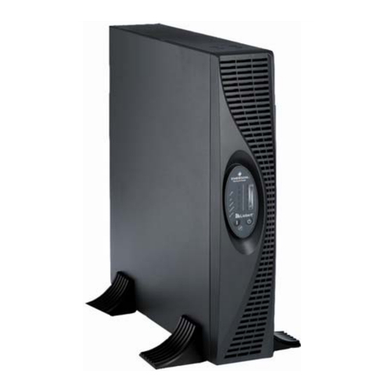
GXT RT Series 1-3 kVA UPS
User Manual
Version:
Revision date:
Emerson Network Power provides customers with technical support. Users may contact the nearest
Emerson local sales office or service center.
While every precaution has been taken to ensure accuracy and completeness in this manual,
Emerson Network Power assumes no responsibility and disclaims all liability for damages resulting
from use of this information or for any errors or omissions.
Emerson Network Power pursues a policy of continuous product development and reserves the
right to change the equipment design without notice.
Copyright © 2005 by Emerson Network Power
All rights reserved. The contents in this document are subject to change without notice
V1.11
Sept 21, 2005
Advertisement
Table of Contents

Subscribe to Our Youtube Channel
Related Manuals for Emerson GXT-RT series


Summary of Contents for Emerson GXT-RT series
- Page 1 V1.11 Revision date: Sept 21, 2005 Emerson Network Power provides customers with technical support. Users may contact the nearest Emerson local sales office or service center. While every precaution has been taken to ensure accuracy and completeness in this manual, Emerson Network Power assumes no responsibility and disclaims all liability for damages resulting from use of this information or for any errors or omissions.
-
Page 2: Table Of Contents
4 Maintenance .................22 4.1 Battery Maintenance..............22 4.2 Replacing Output Fuse ............22 4.3 Checking UPS Functions............22 4.4 Troubleshooting ..............23 5 Specifications................25 5.1 Mechanical................25 5.2 Electrical ................25 5.3 EMS ..................26 5.4 EMI ..................27 5.5 Environmental ................27 5.6 Safety..................27 Page 2 9/2005 Emerson Network Power... -
Page 3: Safety Instructions
BUS-capacitors • As dangerous voltages are present within the UPS, only an Emerson technician or an Emerson-authorized technician is permitted to open it. Failure to observe this could result in electric shock risk and invalidation of any implied warranty. -
Page 4: Safety Instructions
& maintained periodically and if required should be replaced. This is to ensure normal UPS operation and adequate autonomy time. Only an Emerson-authorized technician is permitted to replace the battery. In replacement of battery or battery module, please use the same model and number of battery or battery module. -
Page 5: Description Of Commonly Used Notations
Description of commonly used notations Some or all of the following Notations may be used in this manual and may appear in your application process. Therefore, all users should be familiar with them and understand their explanations. Page 5 9/2005 Emerson Network Power... -
Page 6: Product Description
1-3 kVA UPS Product Introduction Product Introduction The GXT-RT series 1~3kVA UPS is an online UPS with a sine wave output, and is developed by Emerson Network Power. The GXT-RT provides highly efficient and reliable AC Power for your sensitive equipment. - Page 7 (3kVA power modules only), external battery socket (except for 1kVA standard power module), DB9 communication port and SNMP card slot. Figure 1-2 Rear panel of 1kVA standard power module Figure 1-3 Rear panel of 1kVA extended back-up time power module Page 7 9/2005 Emerson Network Power...
-
Page 8: Battery Module
Front panel and rear panel appearances The GXT2000-BAT and GXT3000-BAT battery modules have the same front panel and rear panel, as respectively shown in Figure 1-7 and Figure 1-8. Figure 1-7 Front panel of battery module Page 8 9/2005 Emerson Network Power... -
Page 9: System Type And Configuration
GXT1000L-RT 1 back-up time UPS module needed and should be Extended 2kVA extended Power provided by users. backup GXT2000L-RT 1 Emerson battery and back-up time UPS module time battery cabinet are 3kVA extended Power GXT3000L-RT 1 recommended back-up time UPS... -
Page 10: Operating Principle
GXT3000L-RT extended back-up time power modules provides 8A charging current. Battery: Sealed maintenance-free lead-acid battery is used as the DC source of the UPS. UPS output: this module contains output EMI suppression filter and provides multiple AC outputs for load. Page 10 9/2005 Emerson Network Power... -
Page 11: Communication
The SNMP card slot is designed for installing the SNMP card option, which enables users to monitor the UPS over network. It is also used for auto-shut down of computers in a network. Please consult Emerson representative for detailed monitoring options that are available for this UPS product. -
Page 12: Installation
3. When adopting rack installation, the UPS must be installed in a standard 19-inch equipment rack at least 400mm deep. The user should provide the installation fittings and screws in the rack. Page 12 9/2005 Emerson Network Power... -
Page 13: Tower Installation
Figure 2-3; likewise, make another base and put it down flat on the installation surface. Figure 2-3 Making base Page 13 9/2005 Emerson Network Power... -
Page 14: Rack Installation
Fix the module onto the rack using four screws (provided by the user), as shown in the figure below. Figure 2-7 Installing power module Page 14 9/2005 Emerson Network Power... -
Page 15: Installing Power Module Plus Battery Module
PE terminal of the battery cabinet (refer to the Battery Cabinet User Manual) respectively. 4. Plug the battery cable into the external battery socket on the rear panel of the power module. Page 15 9/2005 Emerson Network Power... -
Page 16: Connecting Input And Output Cables
(5~12Vdc, for more than 20s), the UPS is turned off; when open or at low level input, the UPS 8, 9 On Battery (output dry contact) maintains the original state. Page 16 9/2005 Emerson Network Power... - Page 17 Figure 2-10 Dry contact port schematic diagram SNMP card slot For those that use the SNMP card to monitor the UPS, please refer to the SNMP Card User Manual for the SNMP card installation and communication connection instructions. Page 17 9/2005 Emerson Network Power...
-
Page 18: Operation
UPS to Standby state. LED indicators The indications of the BATTERY indicator, INVERTER indicator, BYPASS indicator, LINE indicator and ALARM indicator are described in Table 3-1. Page 18 9/2005 Emerson Network Power... - Page 19 Battery overcharge (in Standby ¤ None state) 22 No battery 6 times ● ¤ ● ON; depending on other conditions; ¤ Flash Note LED 1 is yellow, LED 6 is red, others are green. Page 19 9/2005 Emerson Network Power...
-
Page 20: Operation Mode
Connect the mains input to the UPS, press and hold the ON button for one second until the buzzer beeps. At this point, the UPS begins to conduct self-test. Seconds later, the UPS will Page 20 9/2005 Emerson Network Power... -
Page 21: Conducting Battery Test
In the event of a battery fault during battery test, the UPS will transfer to Normal mode automatically. 2. Through the background monitoring software Users can also initiate battery test through the background monitoring software. For details, please refer to the UPS Monitoring Software User Manual. Page 21 9/2005 Emerson Network Power... -
Page 22: Maintenance
Normal mode and operate normally. 3. The LED indication of the UPS During the check processes stated above, check that the LED indication of the UPS is in line with the UPS operation mode. Page 22 9/2005 Emerson Network Power... -
Page 23: Troubleshooting
1-3 kVA UPS Maintenance 4.4 Troubleshooting In the event of an UPS fault, troubleshoot according to Table 4-1. If the fault persists, seek immediate assistance from the local Emerson customer service office. Table 4-1 UPS troubleshooting table S/N. Fault conditions... - Page 24 Emerson customer service office. Check the UPS for overload and fan obstruction conditions, check that the ambient temperature does not exceed The ALARM LED and 40°C.
-
Page 25: Specifications
50Hz±10%, with the Frequency phase difference less than 3 degrees; the output frequency is 50Hz when the bypass frequency is outside specifications or the bypass voltage is lower than 120Vac Frequency synchronization 1 Hz/s speed Page 25 9/2005 Emerson Network Power... -
Page 26: Ems
ESD immunity IEC61000-4-2 Level 3, criterion B REF immunity IEC61000-4-3 Level 3, criterion A EFTB immunity IEC61000-4-4 Level 4, criterion A Surge immunity IEC61000-4-5 Level 4, criterion B Lightening protection YD/T 944 Level I, 6kV/3kA Page 26 9/2005 Emerson Network Power... -
Page 27: Emi
Normal range Ambient temperature 0°C~40°C Relative humidity 5%~95% Lower than 1500m: no derating; Altitude 1500m~3000m: 1% derating for every 100m rise Storage temperature -25°C~55°C (excluding battery) 5.6 Safety Comply with EN62040-1-1 and CE requirements. Page 27 9/2005 Emerson Network Power...
Need help?
Do you have a question about the GXT-RT series and is the answer not in the manual?
Questions and answers