Table of Contents
Advertisement
Quick Links
Advertisement
Table of Contents
Troubleshooting

Subscribe to Our Youtube Channel
Related Manuals for Emerson Liebert GXT4


Summary of Contents for Emerson Liebert GXT4
- Page 1 Liebert GXT4 UPS 120V/208V 500VA-3000VA ® ™ User Manual...
-
Page 3: Table Of Contents
TABLE OF CONTENTS ..........1 MPORTANT AFETY RECAUTIONS... - Page 4 Shut Down the Liebert GXT4 ..........33 Disconnecting Input Power from the Liebert GXT4....... . 33 .
- Page 5 Liebert GXT4 rack/tower models—front view ........
- Page 6 TABLES Table 1 UPS models, power ratings ............4 Table 2 Input circuit breaker specification .
-
Page 7: Important Safety Precautions
UPS if the front panel indications are not in accordance with these operating instructions or if the UPS performance alters in use. Refer all faults to your local dealer, Emerson Network Power representative or Emerson Network Power Channel Support. - Page 8 The Liebert GXT4-3000RT208 was tested under 20A branch circuit in accordance with the National Electrical Code, ANSI/NFPA 70. To reduce the risk of fire, connect only to a circuit provided with 20A maximum branch overcurrent protection. Battery Safety CAUTION Do not dispose of batteries in a fire. The batteries may explode.
-
Page 9: Glossary Of Symbols
LOSSARY OF YMBOLS Risk of electrical shock Indicates caution followed by important instructions AC input AC output Requests the user to consult the manual Indicates the unit contains a valve-regulated lead acid battery PbH2SO4 Recycle DC voltage Equipment grounding conductor Bonded to ground AC voltage WEEE... -
Page 10: Product Description
ESCRIPTION The Liebert GXT4 is a compact, online uninterruptible power system (UPS) that continuously conditions and regulates its output voltage. The Liebert GXT4 is designed to supply microcomputers and other sensitive equipment with clean sine wave input power. Upon generation, AC power is clean and stable. However, during transmission and distribution it is subject to voltage sags, spikes and complete failure that may interrupt computer operations, cause data loss and damage equipment. -
Page 11: Appearance And Components
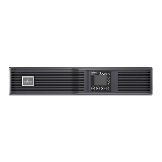
1.3.1 Front Panel and Controls The Liebert GXT4 rack/tower models in various power ratings have the same general appearance, controls and features (see Figure 1). The various rack/tower and minitower models differ largely in the type of receptacles each has. -
Page 12: Figure 3 Rear Panel Components-Liebert Gxt4 120V Rack/Tower, 1500Va Model
Product Description Figure 3 Rear panel components—Liebert GXT4 120V rack/tower, 1500VA model Input Power Plug and Cable Liebert Programmable IntelliSlot General Output Input Circuit Output Port Receptacle Port Breaker Receptacle #2 External Strain Terminal Block Programmable Output RS232 Cooling Battery... -
Page 13: Figure 5 Rear Panel Components-Liebert Gxt4 120V Rack/Tower, 3000Va Model
Product Description Figure 5 Rear panel components—Liebert GXT4 120V rack/tower, 3000VA model Input Power Plug and Cable Liebert IntelliSlot Programmable Port Input Circuit General Output Output USB Port Breaker Receptacle Receptacle #2 Output Terminal Block RS232 Cooling Programmable Output Circuit... -
Page 14: Major Components
DC-to-DC converter, battery, dynamic bypass and UPS output. Transient Voltage Surge Suppression (TVSS) and EMI/RFI Filters The Liebert GXT4 has surge protection and filters that protect the connected load from power surges, electromagnetic interference (EMI) and radio frequency interference (RFI). These features can minimize any surges or interference present in the utility power. -
Page 15: Operating Mode
Optional external battery cabinets are available to extend battery run times. Dynamic Bypass The Liebert GXT4 provides an alternate path for utility power to the connected loads in the unlikely event of a UPS malfunction. Should the Liebert GXT4 have an overload, overtemperature or UPS failure condition, the UPS automatically transfers the connected loads to bypass. -
Page 16: Battery Mode
NOTICE Risk of loss of power to the connected load. Can cause equipment damage. Turning Off the Liebert GXT4 when it is in Battery Mode will result in loss of output power to the connected load. If the UPS is turned Off manually, it must be manually restarted after mains power returns. -
Page 17: Installation
Operating the Liebert GXT4 in temperatures above 77°F (25°C) reduces battery life. Installation Clearances Maintain at least 4 inches (100mm) clearance in the front and rear of the Liebert GXT4. Do not obstruct the air inlets on the front panel and rear panel of the UPS; blocking the air inlets reduces ventilation and heat dissipation, shortening the service life of the Liebert GXT4. -
Page 18: Mechanical Installation
Installation Mechanical Installation The Liebert GXT4 may be installed as a tower or in a rack, depending on space and use considerations. The Liebert GXT4 may be used alone, as a single UPS, or with up to four battery cabinets. -
Page 19: Rack Installation
The Liebert GXT4 UPS and external battery cabinets (EBC), when installed in a rack enclosure, must be supported by a shelf or rack-mount rails. The Liebert GXT4 UPS and EBC units ship with all required hardware to allow rack-mount installation (not included with model numbers that end in “E”). -
Page 20: Cable Connection
Installation Cable Connection The Liebert GXT4 rear panel has an input cable and plug, output receptacles and output cable(s) (Output cables are on GXT4-3000 models only). Refer to 1.3.2 - Rear Panel Features for details. The battery cables are supplied with the battery cabinet. -
Page 21: Connecting Battery Cables
Installing the Optional Liebert IntelliSlot Card and Communication Cables 1. Remove the protective cover of the Liebert IntelliSlot port on the Liebert GXT4 and set it aside. 2. Insert the Liebert IntelliSlot card into the Liebert IntelliSlot port and secure it with screws. -
Page 22: Operation And Display Panel
This chapter describes the Liebert GXT4 controls, particularly the operation and display panel on the front of the Liebert GXT4. The panel has four control buttons, seven LED indicators and a liquid crystal display (LCD), as shown in Figure 14. -
Page 23: Control Buttons
Pressing this button can enter the next level menu or confirm the parameter setting value. The LCD panel shows the UPS status and enables changes to the UPS settings by assisting in navigating through the Liebert GXT4’s menu (see 3.4 - Menu Structure). ®... -
Page 24: Menu Structure
Operation and Display Panel Menu Structure The menu structure of the LCD is shown in Figure 15. Figure 15 Menu structure Audible Alarm Output Startup on Bypass Load Enable Auto Shutdown Status Input Enable Auto Restart Battery Start Windows Frequency Selection Time Since Startup Output Level Selection System... -
Page 25: Startup Screen
Operation and Display Panel 3.4.1 Startup Screen When the Liebert GXT4 is starting up, it initiates a self-test and displays the screen shown in Figure 16 for about 10 seconds. Figure 16 Startup screen EMERSON Network Power After about 10 seconds, the LCD shows one of the On screens in Figure 17; the screen shown depends on whether input power is available. -
Page 26: Default Screen
Operation and Display Panel 3.4.2 Default Screen Press any button in the START SUCCESSFUL screen to enter the default interface, shown in Figure 19. Figure 19 Default screen Values shown will vary GXT4-UPS 3KVA according to installation and configuration. O/P: 120V 60HZ 11.7A I /P: 120V 60HZ 13.1A BATT: 100 % 3MINS LOAD: 100%... -
Page 27: Figure 21 Status Screens
Operation and Display Panel STATUS Screen In the MAIN MENU screen, select STATUS to enter the Status Screen, displaying OUTPUT, LOAD, INPUT, BATTERY and TIME SINCE STARTUP, as shown in Figure 21. Figure 21 Status screens OUTPUT LOAD INPUT VOLT 120V VOLTAGE 120V... -
Page 28: Figure 23 Ups Screens
Operation and Display Panel UPS Screen Select MAIN MENU > CONFIGURATION > UPS to enter the UPS screen. This menu has six screens, as shown in Figure 23. Figure 23 UPS screens AUDIBLE ALARM STARTUP ON BYPASS GUARANTEE SHUTDOWN ENABLE AUTO RESTART FREQUENCY SELECTION VOLTAGE SELECTION AUTO - BYPASS ENABLE... -
Page 29: Figure 25 Eco Mode Screen
Operation and Display Panel ECO Mode Screens Select MAIN MENU > CONFIGURATION > ECO MODE to enter the ECO MODE screens, as shown in Figure 25. Figure 25 ECO Mode screen ECO MODE VOLTAGE TOLERANCE FREQUENCY TOLERANCE REQUALIFICATION TIME 3 Hz 5 MINS Press the Up or Down button to move the cursor to the required item, and press the Enter button to confirm the settings. -
Page 30: Figure 27 Outlet Control Screen
Operation and Display Panel Select 1 OUTLET CONTROL and press the Enter button to enter the OUTLET CONTROL screen, as shown in Figure 27. Figure 27 Outlet Control screen OUTLET CONTROL OUTLET CONTROL TURN OFF TURN ON REBOOT Outlet Control is On Outlet Control is Off Press the Up or Down button to move the cursor to the required item, and press the Enter button to confirm the settings. -
Page 31: Figure 29 Outlet2 Setting Screen
Select 1 LANGUAGE and press the Enter button to enter the LANGUAGE screen, as shown in Figure 31. The Liebert GXT4 is capable of supporting multiple languages. For the list of supported languages and instructions on how to upload them, refer to the Configuration Program user manual on the included CD. -
Page 32: Figure 32 Color Screen
Operation and Display Panel Select ‘2 COLOR’ and press the Enter button to enter the COLOR screen, as shown in Figure 32. Figure 32 Color screen EMERSON EMERSON EMERSON EMERSON FACTORY DEFAULT screen Select MAIN MENU -> 2 CONFIGURATION -> 7 FACTORY DEFAULT to enter the FACTORY DEFAULT screen, as shown in Figure 33. -
Page 33: Figure 35 Turn Ups On Or Off Screen
Operation and Display Panel TURN ON & OFF screen Select MAIN MENU -> 3 CONTROL -> 1 TURN ON & OFF to enter the TURN ON & OFF screen. This screen shows one of two displays, TURN ON UPS and TURN OFF UPS, depending on the state of the UPS, as shown in Figure 35. -
Page 34: Figure 38 Log Screens
Operation and Display Panel Log Screen Select MAIN MENU -> 4 LOG to enter the LOG screen. This screen has two submenus, VIEW LOG and CLEAR LOG, as shown in Figure 38. Figure 38 Log screens 254 /255 1 VIEW LOG 255 OD 1H 17m AGO 2 CLEAR LOG UPS switch to Online... -
Page 35: Figure 41 Network Screens
Operation and Display Panel Network Select MAIN MENU>NETWORK to enter the NETWORK screen. The NETWORK screen displays the MAC address and the IPv4 IP address. If the Liebert GXT4 is ® fitted with an optional Liebert IntelliSlot Web card (Liebert IS-WEBCARD), the screen will display IPv6 IP address settings (IPv6 requires configuration), as shown in Figure 41. -
Page 36: Prompt List
Operation and Display Panel 3.4.4 Prompt List A prompt screen is displayed during the operation of the system to alert you to certain conditions and/or to require your confirmation of a command or other operation. See Table 5 for the prompts and meanings. -
Page 37: Fault List
Operation and Display Panel 3.4.6 Fault List All UPS fault messages are described in Table 7. Table 7 Fault list Fault Description UPS Self-Test Failed The battery is bad or weak or not connected. UPS Overload The UPS is overloaded. Inverter Out Of Order The inverter has failed. -
Page 38: Operation
UPS and disconnecting mains power from the UPS. NOTE The Liebert GXT4’s battery has been fully charged before delivery, but some charge will be lost during storage and shipping. To ensure that the battery has adequate reserve power to protect the connected load, charge the battery for three hours before putting the UPS into service. -
Page 39: Shut Down The Liebert Gxt4
Disconnecting Input Power from the Liebert GXT4 1. After the UPS has been shut down as detailed in 4.5 - Shut Down the Liebert GXT4, disconnect the input cable from the wall socket. 2. Wait 30 seconds and verify that all indicators have turned Off and the fan has stopped; this indicates that the power-off is complete. -
Page 40: Communication
Follow instructions provided with the Liebert IntelliSlot card to configure Liebert MultiLink , the ® UPS or any additional ancillary product for the Liebert GXT4. These instructions are available at: multilink.liebert.com 5.1.1 Liebert MultiLink Liebert MultiLink monitors the UPS continuously and can shut down the computer or server in the event of an extended power failure. -
Page 41: Configuration Program
Communication 5.2.1 Configuration Program The configuration program is on the Liebert GXT4 CD and can be used instead of making configuration setting changes from the LCD panel. The configuration program communicates to a ® ® computer running a Microsoft Windows operating system via the included USB cable. -
Page 42: Rs-232 Port
When the Auto-Enable output option is selected and the UPS output is disabled using Pin 1 and Pin 2, the Liebert GXT4’s output can turn On automatically and without warning if the Pin 1 and Pin 2 connection is changed. -
Page 43: Battery Mode Shutdown
This timer cannot be stopped once triggered. If the mains power returns during this countdown, the Liebert GXT4 will still shut down and must remain shut down for 10 seconds. Whether the UPS turns back On when the power is restored depends on the auto-restart setting. -
Page 44: Maintenance
• Handle, transport and recycle batteries in accordance with local regulations. Replacing the Internal Battery Pack The Liebert GXT4 is designed to allow the user to replace the internal battery pack safely. Refer to Table 9 for internal battery pack part numbers for Liebert GXT4 UPS:... -
Page 45: Battery Replacement Procedures
Maintenance 6.1.1 Battery Replacement Procedures 1. Remove the front plastic bezel cover from the UPS. 2. Loosen and remove the six screws on the battery door, as shown in Figure 43. 3. Lay the battery door and screws aside for reassembly. Figure 43 Removing the front bezel cover and battery door 4. -
Page 46: Battery Charging
The Liebert GXT4 charges the batteries continuously when it is connected to the utility input power. If the Liebert GXT4 will be stored for a long time, Emerson recommends connecting the UPS to input power for at least 24 hours every four to six months to ensure full recharge of the batteries. -
Page 47: Troubleshooting
UPS Symptoms The following symptoms indicate the Liebert GXT4 is malfunctioning: • The relative indicators illuminate, indicating the UPS has detected a problem. • An alarm buzzer sounds, alerting the user that the UPS requires attention. -
Page 48: Audible Alarm
When reporting a UPS issue to Emerson, include the UPS model and serial number. These are located in several places for your ease of location: on the top panel (rack mount orientation); the left side (tower orientation);... -
Page 49: Battery Cabinet
Optional battery cabinets are available for the Liebert GXT4. The battery connectors and input breaker are on the battery cabinet’s rear panel, as shown in Figure 46. For battery cabinet specifications, refer to Table 15. The Liebert GXT4 may be equipped with a maximum of six extension battery packs. -
Page 50: Specifications
Specifications PECIFICATIONS Table 13 Specifications of GXT4-500RT120 - GXT4-700RT120 and GXT4-1000RT120 models Product Model GXT4-500RT120 GXT4-700RT120 GXT4-1000RT120 Parameters (500VA/450W) (700VA/630W) (1000VA/900W) Dimensions, D × W × H, in. (mm) 16.2 x 16.9 x 3.4 Unit (408 x 430 x 85) 25.5 x 23.9 x 10.6 Shipping (647 x 607 x 270) -
Page 51: Table 14 Specifications Of Gxt4-1500Rt120 - Gxt4-3000Rt120 And Gxt4-3000Rt208 Models
Specifications Table 14 Specifications of GXT4-1500RT120 - GXT4-3000RT120 and GXT4-3000RT208 models Product Model GXT4-1500RT120 GXT4-2000RT120 GXT4-3000RT120 GXT4-3000RT208 Parameters (1500VA/1350W) (2000VA/1800W) (3000VA/2700W) (3000VA/2700W) Dimensions, D × W × H, in. (mm) 19.7 x 16.9 x 3.4 23.7 x 16.9 x 3.4 Unit (497 ×... -
Page 52: Table 15 Operating Temperature Parameters
Specifications Table 15 Battery cabinet specifications Model Number Parameter GXT4-48VBATT GXT4-72VBATT GXT4-500RT120,GXT4-700RT120 GXT4-1000RT120,GXT4-1500RT120, GXT4-3000RT120 Used w/UPS Model GXT4-2000RT120 GXT4-3000RT208 Dimensions, D × W × H, in (mm) 19.7 x 16.9 x 3.3 23.7 x 16.9 x 3.3 Unit (497 × 430 × 85) (602 ×... -
Page 53: Table 17 Battery Run Times
Specifications Table 17 Battery run times 208VAC 120VAC RT Models RT Model Number of External Load Percent Battery Cabinets of Capacity 500VA 700VA 1000VA 1500VA 2000VA 3000VA 3000VA Internal Battery 100% Internal Battery + 1 External Battery Cabinet 100% Internal Battery + 2 External Battery Cabinets 100%... - Page 54 Specifications Table 17 Battery run times (continued) 208VAC 120VAC RT Models RT Model Number of External Load Percent Battery Cabinets of Capacity 500VA 700VA 1000VA 1500VA 2000VA 3000VA 3000VA Internal Battery + 4 External Battery Cabinets 100% Internal Battery + 5 External Battery Cabinets 100% Internal Battery...
-
Page 55: Product Warranty Registration
• To contact warranty support by e-mail: dpg.warranty@emerson.com Technical Support Technical support contacts are listed on the back cover of this document. To contact Emerson Channel Product Support: Phone • NORTH AMERICA: 1-800-222-5877 • OUTSIDE NORTH AMERICA: 00-800-1155-4499 E-mail •... - Page 56 Philippines ® Liebert is a registered trademark of Liebert Corporation. +63 2 687 6615 All names referred to are trademarks Fax: +63 2 730 9572 or registered trademarks of their respective owners. SL-23193_REV0_10-14 Emerson Network Power Liebert www.emerson.com...
Need help?
Do you have a question about the Liebert GXT4 and is the answer not in the manual?
Questions and answers