Emerson GXT4-5000RT230 User Manual
Liebert gxt4 230 v, 5000 va – 10,000 va
Hide thumbs
Also See for GXT4-5000RT230:
- User manual (56 pages) ,
- User manual (13 pages) ,
- User manual (50 pages)
Table of Contents
Advertisement
Quick Links
Advertisement
Table of Contents
Troubleshooting

Related Manuals for Emerson GXT4-5000RT230


Summary of Contents for Emerson GXT4-5000RT230
- Page 1 Liebert GXT4 UPS 230 V, 5000 VA – 10,000 VA ® ™ User Manual...
-
Page 3: Table Of Contents
Table of Content Important Safety Precautions........1 Glossary of Symbols. - Page 4 2.4 Install the Main Cabinet........... 14 2.4.1 Tower UPS Installation .
- Page 5 5.0 Communication ..........39 5.1 Liebert IntelliSlot Communication Cards .
- Page 6 List of Figures Figure 1-1: Liebert GXT4 5000VA and 6000VA, front view ......... . . 6 Figure 1-2: Rear panel—5000VA and 6000VA.
- Page 7 Figure 6-2: Disconnecting the battery plug and battery receptacle (front view) ......46 Figure 6-3: Pull out the battery..............47 ®...
- Page 8 List of Tables Table 1-1: UPS models, power ratings............5 Table 2-1: Branch circuit breaker ratings .
-
Page 9: Important Safety Precautions
Do not continue to use the UPS if the front panel indications are not in accordance with these operating instructions or if the UPS performance alters in use. Refer all faults to your local dealer, Emerson Network Power representative or Emerson Network Power Channel Support. -
Page 10: Battery Safety
This UPS is not intended for use with life support and other designated critical devices. Maximum load must not exceed that shown on the UPS rating label. This UPS is designed for data processing equipment. If uncertain, consult your local dealer or Emerson representative. Battery Safety WARNING Risk of electric shock and explosion. - Page 11 Important Safety Precautions NOTICE TO EUROPEAN UNION CUSTOMERS: DISPOSAL OF OLD APPLIANCES—This product has been supplied from an environmentally aware manufacturer that complies with the Waste Electrical and Electronic Equipment (WEEE) Directive 2002/96/CE. The “crossed-out wheelie bin” symbol at right is placed on this product to encourage you to recycle wherever possible.
-
Page 12: Glossary Of Symbols
Glossary of Symbols Glossary of Symbols Risk of electrical shock Indicates caution followed by important instructions AC input AC output Requests the user to consult the manual Indicates the unit contains a valve-regulated lead acid battery PbH2SO4 Recycle DC voltage Equipment grounding conductor Bonded to ground AC voltage... -
Page 13: Product Description
• Output voltage selection function 1.2 Available Models Available models of the UPS are listed in Table 1-1: Table 1-1 UPS models, power ratings Model Number Nominal Power Rating GXT4-5000RT230 5000VA / 4000W GXT4-5000RT230E GXT4-6000RT230 6000VA / 4800W GXT4-6000RT230E GXT4-10000RT230... -
Page 14: Appearance And Components
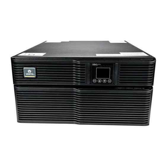
Product Description 1.3 Appearance and Components 1.3.1 Appearance The Liebert GXT4 rack/tower models in various power ratings have the same general appearance, controls and features (see Figure 1-1). The various rack/tower models differ largely in the type of receptacles each has. Figure 1-1 Liebert GXT4 5000VA and 6000VA, front view Upper Bezel Operation and Display Panel... -
Page 15: Figure 1-2 Rear Panel-5000Va And 6000Va
Product Description Figure 1-2 Rear panel—5000VA and 6000VA Terminal Block Liebert GXT4, 5000 & 6000VA Communication REPO C19 Output Power ® Liebert IntelliSlot Port USB Port Receptacles External Battery Connector Output Circuit Breakers IT Power System Access Cover Output Circuit C13 Output Breakers Receptacles... -
Page 16: Removable Power Distribution Box
Product Description 1.4 Removable Power Distribution Box The UPS is shipped with a power-distribution pack installed. This box contains the UPS input circuit breaker. Figure 1-4 Power distribution box for 5000 VA and 6000 VA models Outer Surface View Quick-Connect Figure 1-5 Power distribution box for 10,000 VA models Quick-Connects Inner Surface View... -
Page 17: Major Components
Product Description 1.6 Major Components The UPS is composed of mains input, TVSS and EMI/RFI filters, rectifier/PFC, inverter, battery charger, DC-to-DC converter, battery, dynamic bypass and UPS output. General Dynamic Outlet POD Bypass Dependent Rectifier/ TVSS EMI/RFI Inverter General EMI/RFI Output DC-DC Outlet POD... -
Page 18: Dc-To-Dc Converter
Product Description 1.6.5 DC-to-DC Converter The DC-to-DC converter utilizes energy from the battery system and raises the DC voltage to the optimum operating voltage for the inverter. This allows the inverter to operate continuously at its optimum efficiency and voltage, thus increasing reliability. 1.6.6 Battery The Liebert GXT4 utilizes valve-regulated, nonspillable, lead acid batteries. -
Page 19: Battery Mode
Product Description 1.7.3 Battery Mode The Liebert GXT4 enters Battery Mode when mains power fails or is outside acceptable limits. The battery system supplies power through the DC-to-DC converter to the inverter to generate clean AC power for the connected loads. When the Liebert GXT4 enters Battery Mode, the UPS sounds a half-second beep at 10-second intervals. -
Page 20: Active Eco Mode
Product Description 1.7.6 Active ECO Mode All Liebert GXT4 models can operate in Active ECO Mode. In this mode, the connected equipment is powered through the bypass path to increase efficiency, reducing the electrical costs. Active ECO mode keeps the rectifier and inverter operating, allowing the inverter to remain synchronized to bypass. -
Page 21: Installation
® representative immediately. • Check the accessories against the delivery list. If there is any discrepancy, contact your local dealer or your Emerson representative immediately CAUTION The UPS is heavy (see 8.0 - Specifications). Take proper precautions when lifting or moving it. -
Page 22: Preparation For Installation
Installation 2.3 Preparation for Installation 2.3.1 Installation Environment Install the Liebert GXT4 indoors in a controlled environment, where it cannot be accidentally turned Off. Place it where air flows unrestricted around the unit. The installation location must be free of water, flammable liquids, gases, corrosives and conductive contaminants. -
Page 23: Rack Installation
Installation 4. Adjust the direction of the operation and display panel and logo on the Liebert GXT4. a. Remove the front plastic bezel cover as shown in Figure 2-2. Figure 2-2 Remove the front plastic bezel cover Front plastic bezel cover b. -
Page 24: External Battery Cabinet Installation
2. Optional rack-mount hardware is shipped with the external battery cabinet and may be installed at this time if desired. • Securing hardware and slide rails are sold separately. Please contact your local dealer or Emerson representative for these additional options and any assistance needed. Fasten the slides into position with the screws per the instructions included with the slide rails. -
Page 25: Connect Input/Output Power
Installation 7. Verify the circuit breaker on the External Battery Cabinet is in the On position. 8. Use the included configuration program or the LCD to program the UPS with the number of external battery cabinets connected. Instructions for the configuration program are in 5.2.1 - Configuration Program. -
Page 26: Distribution Box Electrical Connections
Installation NOTICE The load is unprotected from disturbances in the power supply while the UPS is on bypass. 2. Turn the output and input breakers Off. 3. Loosen other captive screws until the power distribution box releases. 4. Remove the power distribution box from the UPS and set it aside. 5. -
Page 27: Terminal Block Connections
2.6.3.1 Terminal Block Connections Conduit entry holes are provided on the rear and side of the box. Input and output wiring should not share the same conduit. Emerson recommends using strain relief when installing the wire. Table 2-2 Electrical specifications... -
Page 28: It Power System Configuration
Installation 2.7 IT Power System Configuration 1. Remove screws on the IT Power System Access Cover as shown in Figure 3. 2. Disconnect the connectors as shown in figure. 3. Install IT Power System Access Cover and screws. Figure 3 Remove cover from IT Power System Connectors compartment IT Power System Remove Screws... -
Page 29: Operation And Display Panel
Operation and Display Panel 3.0 Operation and Display Panel This chapter describes the Liebert GXT4 controls, particularly the operation and display panel on the front of the Liebert GXT4. The panel has four control buttons, seven LED indicators and a liquid crystal display (LCD), as shown in Figure 3-1. -
Page 30: Control Buttons
Operation and Display Panel 3.2 Control Buttons The four control buttons on the front of the operation and display panel are: • ESC • Up • Down • Enter Figure 3-1 shows the buttons’ locations; their descriptions and functions are shown in Table 3-2. Table 3-2 Control buttons Control Buttons... -
Page 31: Menu Structure
Operation and Display Panel 3.4 Menu Structure The menu structure of the LCD is shown in Figure 3-2. Figure 3-2 Menu structure Audible Alarm Output Startup on Bypass Load Enable Guaranteed Status Shutdown Input Enable Auto Restart Battery Start Windows Frequency Selection Time Since Startup Output Level Selection... -
Page 32: Startup Screen
When the Liebert GXT4 is starting up, it initiates a self-test and displays the screen shown in Figure 3-3 for about 10 seconds. Figure 3-3 Startup screen EMERSON Network Power After about 10 seconds, the LCD shows one of the On screens in Figure 3-4; the screen shown depends on whether input power is available. -
Page 33: Default Screen
Operation and Display Panel 3.4.2 Default Screen Press any button in the START SUCCESSFUL screen to enter the default interface, shown in Figure 3-6. NOTE Values shown in the default screen will vary depending on installation and configuration. In the default screen, the LCD shows the UPS model, output parameters, input parameters, battery capacity with run time estimate and load percentage. -
Page 34: Figure 3-8: Status Screens
Operation and Display Panel STATUS Screen In the MAIN MENU screen, select STATUS to enter the Status Screen, displaying OUTPUT, LOAD, INPUT, BATTERY and TIME SINCE STARTUP, as shown in Figure 3-8. Figure 3-8 Status screens OUTPUT LOAD INPUT VOLT 120V VOLTAGE 120V... -
Page 35: Figure 3-10: Ups Screens
Operation and Display Panel UPS Screen Select MAIN MENU > CONFIGURATION > UPS to enter the UPS screen. This menu has six screens, as shown in Figure 3-10. Press the Up or Down button to move the cursor to the required item, and press the Enter button to confirm the settings. -
Page 36: Figure 3-12 Eco Mode Screen
Operation and Display Panel ECO Mode Screens Select MAIN MENU > CONFIGURATION > ECO MODE to enter the ECO MODE screens, as shown in Figure 3-12. Press the Up or Down button to move the cursor to the required item, and press the Enter button to confirm the settings. -
Page 37: Figure 3-14 Language Screen
Configuration Program user manual on the included CD. Figure 3-14 Language screen 1 English Select ‘2 COLOR’ and press the Enter button to enter the COLOR screen, as shown in Figure 3-15. Figure 3-15 Color screen EMERSON EMERSON EMERSON EMERSON FACTORY DEFAULT screen Select MAIN MENU ->... -
Page 38: Figure 3-17 Control Screen
Operation and Display Panel Control Screen Select MAIN MENU -> 3 CONTROL to enter the CONTROL screen. This screen has three submenus, TURN ON & OFF, ALARM CONTROL and BATT TEST, as shown in Figure 3-17. In the CONTROL screen, press the Up or Down button to move the cursor to the required item, and press the Enter button to enter its submenu. -
Page 39: Figure 3-19 Alarm Control Screen
Operation and Display Panel ALARM CONTROL screen Select MAIN MENU -> 3 CONTROL -> 2 ALARM CONTROL to enter the ALARM CONTROL screen, as shown in Figure 3-19. This section allows active audible alarms to be silenced. To completely turn off the audible alarm, refer to CONFIGURATION >... -
Page 40: Figure 3-22 Clear Log Screen
Operation and Display Panel CLEAR LOG Screen Select MAIN MENU > LOG > CLEAR LOG to enter the CLEAR LOG screen, as shown in Figure 3-22. Press the Up or Down button to move the cursor to the required item. Press the Enter button to confirm the settings. -
Page 41: Figure 3-24: Network Screens
Operation and Display Panel Network Select MAIN MENU>NETWORK to enter the NETWORK screen. The NETWORK screen displays the MAC address and the IPv4 IP address. If the Liebert GXT4 is fitted ® with an optional Liebert IntelliSlot Web card (Liebert IS-WEBCARD), the screen will display IPv6 IP address settings (IPv6 requires configuration), as shown in Figure 3-24. -
Page 42: Prompt List
Operation and Display Panel 3.4.4 Prompt List A prompt screen is displayed during the operation of the system to alert you to certain conditions and/or to require your confirmation of a command or other operation. See Table 3-3 for the prompts and meanings. Table 3-3 System prompts and meanings Prompt... -
Page 43: Fault List
Operation and Display Panel 3.4.6 Fault List All UPS fault messages are described in Table 3-5. Table 3-5 Fault list Fault Description UPS Self-Test Failed The battery is bad or weak or not connected. UPS Overload The UPS is overloaded. Inverter Out Of Order The inverter has failed. - Page 44 Operation and Display Panel Page intentionally left blank. ® ™ Liebert GXT4 User Manual...
-
Page 45: Operation
• If the battery test results show FAILED, allow the UPS to recharge the batteries for 24 hours. • Retest the batteries after 24 hours of charging. • After the batteries have been retested, if the battery test still shows FAILED, contact your local ® Emerson representative or Emerson Network Power Channel Support. ® ™ Liebert GXT4... -
Page 46: Manual Bypass
Operation 4.4 Manual Bypass To manually transfer the connected equipment to the internal bypass: 1. From the main menu select Control then press enter. 2. Select TURN ON & OFF and press Enter. 3. Select TURN UPS BYPASS and press Enter. The UPS will transfer the connected loads to the internal bypass. -
Page 47: Communication
UPS. For more information about the Liebert IntelliSlot SNMP Card, Liebert IntelliSlot Web Card and Liebert ® MultiLink License Kits, visit the Liebert Web site (www.liebert.com) or contact your local Emerson representative. ®... -
Page 48: Usb Port Communication
• Select the number of external battery cabinets connected to the UPS to adjust the remaining run time ® calculated by Emerson software products (default is zero) • Select one of multiple output voltages to match various voltages (see Table 5-1). -
Page 49: Terminal Block Communication
Communication 5.3 Terminal Block Communication The Terminal Block includes eight pins, as shown in Figure 5-1. Figure 5-1 Terminal-block communication pin layout Description Low battery warning On-battery warning Any mode shutdown Battery mode shutdown 5.3.1 Any Mode Shutdown The purpose of Any Mode Shutdown is to shut down the UPS output by turning Off the rectifier, inverter and static switch so that there is no power to the loads. -
Page 50: Battery Mode Shutdown
Communication 5.3.2 Battery Mode Shutdown Battery Mode Shutdown permits shutting down the UPS by turning Off the rectifier, inverter and static switch so that there is no power to the load when the UPS is On Battery. The auxiliary power for the UPS will still be active. -
Page 51: Remote Emergency Power Off-Gxt4-6000Rtl630
Communication 5.4 Remote Emergency Power Off—GXT4-6000RTL630 The UPS is equipped with a Remote Emergency Power Off (REPO) connector. The user must supply a means of interfacing with the REPO circuit to allow disconnecting the UPS input feeder breaker to remove all sources of power to the UPS and connected equipment to comply with national and local wiring codes and regulations. - Page 52 Communication Page intentionally left blank. ® ™ Liebert GXT4 User Manual...
-
Page 53: Maintenance
• Use tools with insulated handles. • Do not lay tools or other metal objects on the batteries. • If the battery kit is damaged in any way or shows signs of leakage, contact your local Emerson representative immediately. • Do not dispose of batteries in a fire. The batteries may explode. -
Page 54: Battery Replacement Procedures
Read all safety cautions before proceeding. A trained user can replace the internal battery pack when the UPS is always in a restricted access location (such as a rack or server closet). Contact your local dealer or Emerson representative to obtain the pricing of the appropriate replacement battery pack. CAUTION Risk of explosion if battery is replaced by an incorrect type. -
Page 55: Battery Charging
The Liebert GXT4 charges the batteries continuously when it is connected to the utility input power. If the Liebert GXT4 will be stored for a long time, Emerson recommends connecting the UPS to input power for at least 24 hours every four to six months to ensure full recharge of the batteries. -
Page 56: Precautions
Support. • Check if the battery is discharging: When the utility input is normal, the battery should not discharge. If the UPS is operating in Battery Mode, stop and contact your local Emerson representative or Emerson Channel Support. 6.5 Checking UPS Functions NOTE UPS function check procedures may interrupt power supply to the connected load. -
Page 57: Troubleshooting
Troubleshooting 7.0 Troubleshooting This section indicates various UPS symptoms a user may encounter and provides a troubleshooting guide in the event the UPS develops a problem. Use the following information to determine whether external factors caused the problem and how to remedy the situation. 7.1 UPS Symptoms The following symptoms indicate the Liebert GXT4 is malfunctioning: •... -
Page 58: Audible Alarm
Check load level indicator and reduce the load on the UPS. backup time Batteries may not be able to Replace batteries. Contact your local dealer, Emerson representative or hold a full charge due to age Emerson Channel Support for replacement battery kit. - Page 59 Troubleshooting When reporting a UPS issue to Emerson, include the UPS model and serial number. These are located in several places for your ease of location: • on the top panel (rack mount orientation) • the left side (tower orientation) •...
- Page 60 Troubleshooting Page intentionally left blank. ® ™ Liebert GXT4 User Manual...
-
Page 61: Specifications
Specifications 8.0 Specifications Table 8-1 UPS specifications GXT4-5000RT230 GXT4-6000RT230 GXT4-10000RT230 Model # GXT4-5000RT230E GXT4-6000RT230E GXT4-10000RT230E Rating 5000VA/4000W 6000VA/4800W 10,000VA/9000W Dimensions, mm (in) Unit, W x D x H 430 x 574 x 217 430 x 581 x 261 (16.9 x 22.4 x 8.5) (16.9 x 22.9 x 10.3) -
Page 62: Table 8-1: Ups Specifications
Specifications Table 8-1 UPS specifications (continued) GXT4-5000RT230 GXT4-6000RT230 GXT4-10000RT230 Model # GXT4-5000RT230E GXT4-6000RT230E GXT4-10000RT230E Bypass Protection Limits Disable Bypass Operation If input voltage exceeds ±15% of the nominal voltage Re-Enable Bypass Operation If input voltage returns to within ±10% of nominal output voltage... -
Page 63: Table 8-3: External Battery Cabinet Specifications
External battery cabinet specifications Model Number GXT4-240VBATT Used with UPS Model GXT4-5000RT230; GXT4-6000RT230; GXT4-10000RT230 Dimensions, W x D x H, mm (in.) Unit (with bezel) 430 x 581 x 173 (16.9 x 22.9 x 6.8) 530 x 745 x 475 (20.9 x 29.3 x 18.7) -
Page 64: Table 8-4 Battery Run Time, Minutes, All Models
Specifications Table 8-4 Battery run time, minutes, all models Number of 230VAC RT Models Load Percent Batteries/Cabinets of Capacity 5kVA 6kVA 10kVA Internal Battery 100% Internal Battery + 1 External Battery Cabinet 100% Internal Battery + 2 External Battery Cabinets 100% Internal Battery + 3 External... - Page 65 Specifications Table 8-4 Battery run time, minutes, all models (continued) Number of 230VAC RT Models Load Percent Batteries/Cabinets of Capacity 5kVA 6kVA 10kVA Internal Battery + 4 External Battery Cabinets 100% 1143 1033 Internal Battery + 5 External Battery Cabinets 100% 1367 1248...
-
Page 66: Auto-Learning Battery Run Times
• To contact warranty support by e-mail: microups.warranty@emerson.com 8.3 Technical Support Technical support contacts are listed on the back cover of this document. To contact Emerson Channel Product Support: Phone • NORTH AMERICA: 1-800-222-5877 • OUTSIDE NORTH AMERICA: 00-800-1155-4499 E-mail •... - Page 68 © 2016 Liebert Corporation All rights reserved throughout the world. Specifications subject to changewithout notice. ® Liebert is a registered trademark of Liebert Corporation. All names referred to are trademarks or registered trademarks of their respective owners. SLI-23197_REV2_5-16 590-1367-501A Emerson Network Power www.emersonnetworkpower.com...
Need help?
Do you have a question about the GXT4-5000RT230 and is the answer not in the manual?
Questions and answers
GXT4-10000RT230 HOW MANY BATTERY 12V -7AH OR 12V9AH
The Emerson GXT4-10000RT230 uses 20 batteries of 12V 9AH.
This answer is automatically generated