
Related Manuals for Emerson Liebert GXT2-10000RT208


Summary of Contents for Emerson Liebert GXT2-10000RT208
- Page 1 AC Power For Business-Critical Continuity™ Liebert GXT2-10000RT208 ® ™ User Manual–10kVA, 60 Hz, 120/208/240V...
-
Page 3: Table Of Contents
TABLE OF CONTENTS ..........1 MPORTANT AFETY NSTRUCTIONS... - Page 4 Configuration Program—Installation ......... . . 21 Establishing Communication Link with the UPS .
- Page 5 11.0 ............32 OMMUNICATIONS 11.1 Communications Interface Port.
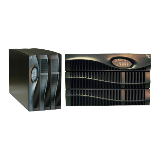
- Page 6 FIGURES Figure 1 10 kVA Dual Inverter Liebert GXT2-10000RT208, front and rear views ....7 Figure 2 Internal battery pack and connector ..........7 Figure 3 Hardwire terminal blocks .
-
Page 7: Important Safety Instructions
MPORTANT AFETY NSTRUCTIONS WARNING Opening or removing the cover may expose you to lethal voltages within this unit even when it is apparently not operating and the input wiring is disconnected from the electrical source. Observe all cautions and warnings in this manual. Failure to do so may result in serious injury or death. - Page 8 When replacing batteries, replace with the same Liebert authorized replacement battery kits. When replacing the power module, replace it with the same Liebert authorized replacement power module kit. CAUTION Do not dispose of battery or batteries in a fire. The battery may explode. Do not open or mutilate the battery or batteries.
-
Page 9: Glossary Of Symbols
Glossary of Symbols LOSSARY OF YMBOLS Risk of electrical shock Indicates caution followed by important instructions AC input AC output Requests the user to consult the manual Indicates the unit contains a valve-regulated lead acid battery PbH2SO4 Recycle DC voltage Equipment grounding conductor Bonded to ground AC voltage... -
Page 10: Introduction And System Description
Introduction and System Description NTRODUCTION AND YSTEM ESCRIPTION Congratulations on your choice of the Liebert GXT2-10000RT208 Uninterruptible Power Supply (UPS). It provides conditioned power to microcomputers and other sensitive electronic equipment. Upon generation, AC power is clean and stable. However, during transmission and distribution it is subject to voltage sags, spikes or complete power failure that may interrupt computer operations, cause data loss or even damage equipment. -
Page 11: System Description
System Description YSTEM ESCRIPTION Input Output Static Bypass TVSS & EMI/RFI Rectifier Inverter Filters /PFC DC to DC Converter Battery Battery Charger Transient Voltage Surge Suppression (TVSS) and EMI/RFI Filters These UPS components provide surge protection and filter both electromagnetic interference (EMI) and radio frequency interference (RFI). -
Page 12: Dc To Dc Converter
System Description DC to DC Converter The DC-to-DC converter utilizes energy from the battery system and raises the DC voltage to the opti- mum operating voltage for the inverter. This allows the inverter to operate continuously at its opti- mum efficiency and voltage, thus increasing reliability. Battery The Liebert GXT2-10000RT208 utilizes valve-regulated, nonspillable, flame retardant, lead acid bat- teries. -
Page 13: Major Components
Major Components AJOR OMPONENTS The Liebert GXT2-10000RT208 is composed of three major assemblies to provide easier handling, installation and versatility. Main Frame and Electronics This 6U cabinet arrives without internal batteries to lighten the UPS for easier installation. Once the cabinet has been placed in its final floor or rack position, the internal batteries may be installed. -
Page 14: Input/Output Terminal Blocks And Optional Output Distribution
Major Components Input/Output Terminal Blocks and Optional Output Distribution The UPS is shipped with hardwire terminal blocks. For maximum flexibility, additional distribution options are available that provide the benefit of output receptacle convenience. Figure 3 Hardwire terminal blocks INPUT OUTPUT Figure 4 Optional output distribution modules PD-101... -
Page 15: What S Included
What’s Included ’ NCLUDED The Liebert GXT2-10000RT208 is shipped Box containing accessories is shipped in the UPS’ with these items: battery compartment • UPS user manual • Vertical display overlay • Front bezels - 3 • Top bezels - 3 •... -
Page 16: Installation And Configuration
Installation and Configuration NSTALLATION AND ONFIGURATION This section includes instructions on how to install, configure and perform initial electrical checks of your UPS installation. DO NOT attempt to start the UPS, turn on any circuit breaker or energize the input power until instructed to do so in 7.0 - Initial Startup and Electrical Checks. -
Page 17: Installing The Adjustable Rack-Mount Kit-Sold Separately
Installation and Configuration 6.1.2 Installing the Adjustable Rack-Mount Kit—Sold Separately This kit contains parts needed to mount several different models of UPS and external battery cabi- nets into EIA310-D standard four-post racks that are 18-32" deep (457-813mm). The weight limit per pair of adjustable rack-mounting brackets is 200 pounds (91 kg). - Page 18 Installation and Configuration 4. Get eight (8) M4 screws and eight (8) M4 nuts from the M4 nuts hardware pack in this kit. Each nut has a locking, nylon screws insert that begins gripping the screw when it is halfway tight.
-
Page 19: External Battery Cabinet Installation
Installation and Configuration External Battery Cabinet Installation Optional Liebert external battery cabinets may be connected to the UPS to provide additional battery run time. External battery cabinets are designed to be placed on one side of the UPS or stacked beneath the UPS. -
Page 20: Connect Input/Output Power
Installation and Configuration Connect Input/Output Power The UPS has hardwire terminal blocks for input and output electrical connections. Optional output distribution modules permit connecting additional loads to the UPS. These optional plug-and-play distribution modules offer different types and numbers of connection plugs. WARNING The UPS must be completely powered down before beginning to make these electrical connections. -
Page 21: Input & Output Terminal Block Connections
Installation and Configuration 6.3.2 Input & Output Terminal Block Connections Conduit entry holes are provided on the rear and side of the box. Input and output wiring should not share the same conduit. Table 1 Electrical requirements Recommended Wire Maximum Wire Terminal Input Current Recommended (Max.) External... -
Page 22: Add An Output Power Distribution Module-Optional
Installation and Configuration 6.3.3 Add an Output Power Distribution Module—Optional To add an optional output distribution module to the Liebert GXT2 10000RT208: 1. Remove the four screws securing the blank output distribution cover plate to the rear of the UPS. The cover is at top left corner in the tower configuration and at the bottom left in the rack configuration. -
Page 23: Install The Internal Battery Packs
Installation and Configuration Install the Internal Battery Packs To facilitate shipping and installation, the Liebert GXT2-10000RT208 ships without the internal bat- tery packs installed. Once the UPS is installed in place, the internal battery packs must be installed. Controls and Indicators (horizontal overlay) L ie b e r t... -
Page 24: Initial Startup And Electrical Checks
Initial Startup and Electrical Checks NITIAL TARTUP AND LECTRICAL HECKS Initial Startup and the Configuration Program—The UPS ships with a default 120 VAC L-N setting. This is also the most robust setting in that it can operate with either input phase angle (120 or 180 degrees). -
Page 25: Output Receptacle Distribution Options
Initial Startup and Electrical Checks 18. Press the On button for one second. The bypass indicator will light for several seconds before the UPS On indicator turns on continuously. If the batteries are charged above 90% of capacity, automatic battery test will run for about 15 seconds. 19. -
Page 26: Configuration Program
Configuration Program ONFIGURATION ROGRAM The final step of installation may require custom configuration of your UPS using the enclosed config- uration program. Some configuration settings may be changed only while the UPS is off. These should be set before the UPS is put into full time service powering the critical load. For most users operating with 120VAC L-N, the factory default settings will be adequate. -
Page 27: Configuration Program-Installation
Configuration Program Configuration Program—Installation An easy-to-use installation program streamlines the installation of the configuration program. If you have a previous version of this configuration program installed, Liebert recommends uninstalling it by using its Uninstall program before installing this updated version. 1. -
Page 28: Configuration Program-Operation
Configuration Program If this message is displayed check the following items: • Verify that the serial communication cable is connected properly. • Verify that the COM port being used is designated COM1 or COM2. • Verify that the UPS is either in Inverter mode, Bypass mode, Battery mode, or Off with AC power available at the input (AC Input LED on). -
Page 29: On-Screen Reminders
Configuration Program 8.5.4 On-Screen Reminders As pending changes are selected, on-screen messages will remind the user if the UPS may be On, or must be Off, for the setting to be pro- grammed once the Apply or OK button is pressed. -
Page 30: Ups Tab
Configuration Program UPS Tab When the program starts, the following window will open displaying the UPS model along with the current UPS settings. This information can be refreshed at any time using the REFRESH button. These illustrations show the factory default settings for 120VAC UPS at the left, and output L-N volt- ages available to select at the right. -
Page 31: Frequency Selection
Configuration Program 8.6.3 Frequency Selection The UPS is normally designed for 50Hz or 60Hz operation. The factory default corresponds to the model. All models are capable of being used as 50Hz or 60Hz systems. The UPS will Auto-sense the utility frequency when first plugged in and set the nominal frequency to match. Therefore, for all nor- mal use the Auto Sense button should be selected. -
Page 32: Options Tab Used With Earlier Liebert Gxt2 Models
Configuration Program Options Tab Used With Earlier Liebert GXT2 Models This version of the configuration program will accompany Liebert GXT2 UPS models that support new programming features accessible using the Options Tab. If Version 1.6 (or later) is used with an earlier Liebert GXT2 model (with an earlier UPS firmware version), the Any Mode Shutdown features cannot be changed. -
Page 33: Battery Tab
Configuration Program Battery Tab Factory default settings illustrated. The boxes above show options available in the drop-down menus. The Liebert GXT2-10000RT208 automatically detects external battery cabinets when they are connected. Use the Battery Cabinets Number selection box to select non-Liebert battery cabinets when used with the UPS. -
Page 34: About Tab
Configuration Program 8.10 About Tab Version number may be confirmed using the About Tab. -
Page 35: Controls And Indicators
Controls and Indicators ONTROLS AND NDICATORS Figure 8 Control and indicator overlays, vertical and horizontal All indicators lit for illustrative purposes. Vertical overlay for tower installation Horizontal overlay for rack mounting ON/Alarm Silence/Battery Test Button This button controls output power to connected load(s) and has three functions: •... -
Page 36: L1 & L2 Load Level Indicators (Two Rows Of Indicators: 4 Green, 1 Amber)
Controls and Indicators L1 & L2 Load Level Indicators (Two Rows of Indicators: 4 Green, 1 Amber) The Load Level indicators display the approximate electrical load placed upon both output legs of the UPS at all times. Each indicator represents an approximate 25 percent increase in load. For optimum utilization of the UPS, distribute L-N loads to approximately balance the loads on L1 and L2. -
Page 37: Modes Of Operation
Modes of Operation 10.0 M ODES OF PERATION 10.1 Normal Mode Operation During normal operation, utility power provides energy to the UPS. The filters, power factor correction circuit and the inverter process this power to provide computer grade power to connected loads. The UPS maintains the batteries in a fully charged state. -
Page 38: Communications
Communications 11.0 C OMMUNICATIONS 11.1 Communications Interface Port The Liebert GXT2-10000RT208 UPS has a standard DB-9 serial port female connector located on the rear of the UPS unit. Several signals are provided on this port and are assigned as follows: Table 2 DB-9 pin assignment DB-9... -
Page 39: 11.1.2 Communications-Liebert Snmp/Ocwebcard Snmp Adapter
Communications 11.1.2 Communications—Liebert SNMP/OCWEBCARD SNMP Adapter Attach the larger enclosed ferrite bead clamp to the network cable, see illustration at right, using the following directions: 1. Open the ferrite bead. 2. Place the network cable inside the ferrite bead groove. 3. -
Page 40: Remote Emergency Power Off
Communications 11.4 Remote Emergency Power Off The UPS is equipped with a Remote Emergency Power Off (REPO) connector. The user must supply a means of interfacing with the REPO circuit to allow disconnecting the UPS input feeder breaker to remove all sources of power to the UPS and connected equipment to comply with national and local wiring codes and regulations. -
Page 41: Maintenance
Maintenance 12.0 M AINTENANCE The Liebert GXT2-10000RT208 requires very little maintenance. The batteries are valve-regulated, non-spillable, flame retardant, lead acid and should be kept charged to obtain their design life. The UPS continuously charges the batteries when connected to the utility supply. When storing the UPS for any length of time, it is essential to plug the UPS in for at least 24 hours every four to six months to ensure full recharge of the batteries. -
Page 42: Ups Power Module Replacement
Maintenance 12.2 UPS Power Module Replacement CAUTION The UPS must be switched to manual bypass before personnel begin to replace the power module. NOTE During the procedure, the connected load will not be protected from power disturbances, such as spikes, sags and failure. To remove the UPS power module without shutting off power to the connected load: 1. -
Page 43: Figure 10 Ups Back Panel-Control Location
Maintenance Figure 10 UPS back panel—control location Output Input Bypass Inverter Output Breaker 60A 250V~/T Input Breaker 60A 250V~/T Figure 11 Power module replacement Power module pulled out of UPS (Retaining grilles removed for clarity) -
Page 44: Troubleshooting
Troubleshooting 13.0 T ROUBLESHOOTING The information below indicates various symptoms a user may encounter in the event the Liebert GXT2-10000RT208 develops a problem. Use this information to determine whether external factors caused the problem and how to remedy the situation. 1. -
Page 45: Table 4 Alarm Conditions
Troubleshooting Under fault conditions, the Fault indicators will be illuminated indefinitely while the battery charger is operational, or for a maximum of 5 minutes while the battery charger is not operational. If a problem persists, consult your local dealer, Liebert representative or contact the Liebert World- wide Support Group. -
Page 46: Troubleshooting Guide
Troubleshooting Table 5 Troubleshooting guide Problem Cause Solution Ensure the UPS is OFF. Disconnect all loads and ensure UPS fails to start when the UPS is short-circuited or nothing is lodged in output receptacles. ON button is pressed. overloaded. Ensure the loads are not defective or shorted internally. UPS is operating in Battery Mode, make certain UPS is UPS not plugged in. - Page 47 Troubleshooting Table 5 Troubleshooting guide (continued) Problem Cause Solution Fault indicator and diagnostic UPS has shut down due to the REPO (Remote Emergency indicators B and C are REPO is currently activated. Power Off). The output cannot be started by any method. illuminated.
-
Page 48: Battery Run Times
Troubleshooting Using the configuration program, the user may specify the number of GXT2-288VBATT external bat- tery cabinets attached to the UPS. The factory default is programmed for internal batteries only. Table 6 shows estimated run times at different loads. Table 6 Battery run times Battery/External 10000VA Run Time... -
Page 49: Auto-Learning Battery Run Times
Troubleshooting 13.1 Auto-Learning Battery Run Times As batteries age, the estimated run times may become less accurate. The Liebert GXT2-10000RT208 is programmed to “learn” from a full battery discharge and modify the estimated run time for the measured battery capacity. This can improve accuracy and compensate for aging batteries or batter- ies that operate at different ambient temperatures. -
Page 50: Specifications
Specifications 14.0 S PECIFICATIONS Table 7 UPS specifications Model Number Liebert GXT2-10000RT208 8000W/8660VA at 127/220 (120 or 240 degrees only) 8000W/8660VA at 120/208 (120 or 240 degrees) 8000W/10000VA at 120/240 (180 degrees) Model Rating 8000W/10000VA at 115/230 (180 degrees only) 7200W/9000VA at 110/220 (180 degrees only) 6400W/8000VA at 100/200 (180 degrees only) DIMENSIONS, RACK MOUNT, W x D x H... -
Page 51: Table 8 Battery Specifications
Specifications Table 7 UPS specifications (continued) Model Number Liebert GXT2-10000RT208 Bypass Protection Limits Disable Bypass Operation If input voltage exceeds ±15% of the nominal voltage Re-enable Bypass Operation If input voltage returns to within ±10% of nominal output voltage Disable Bypass Operation When the input frequency prevents synchronous operation ENVIRONMENTAL Operating Temp... -
Page 52: Table 10 Optional Output Distribution Specifications-Pd-102
Specifications Table 10 Optional output distribution specifications—PD-102 Model Number PD-102 DIMENSIONS, W x D x H Shipping, in. (mm) 8.86 x 10.43 x 7.87 (225 x 265 x 200) WEIGHT lb (kg) Unit 4.6 (2.1) Shipping 6.0 (2.7) ELECTRICAL SPECIFICATIONS Amp Rating 60 Amps Input Power Connections... -
Page 53: Product Warranty Registration
Specifications Table 13 External battery cabinet specifications Model Number GXT2-288RTVBATT Used w/ UPS Model Liebert GXT2-10000RT208 DIMENSIONS, Rack Mount, W x D x H Unit (with bezel), in (mm) 16.93 x 25.98 x 7 (430 x 660 x 178); 4U Shipping, in (mm) 22.64 x 33.46 x 12.40 (575 x 850 x 315) WEIGHT lb (kg) - Page 54 Specifications...
- Page 56 Racks & Integrated Cabinets Connectivity Embedded Power Power Switching & Controls Services DC Power Monitoring Precision Cooling Surge Protection Business-Critical Continuity, Emerson Network Power and the Emerson Network Power logo are trademarks and service marks of Emerson Electric Co. ©2007 Emerson Electric Co.
Need help?
Do you have a question about the Liebert GXT2-10000RT208 and is the answer not in the manual?
Questions and answers