Emerson Liebert GXT4-5000RT230 User Manual
Liebert gxt4 5000va ~ 10000va (230v)
Hide thumbs
Also See for Liebert GXT4-5000RT230:
- User manual (56 pages) ,
- User manual (68 pages) ,
- User manual (13 pages)
Table of Contents
Advertisement
Advertisement
Table of Contents

Related Manuals for Emerson Liebert GXT4-5000RT230


Summary of Contents for Emerson Liebert GXT4-5000RT230
- Page 1 GXT4™ Liebert ® User Manual – 5000VA ~ 10000VA (230V)
-
Page 3: Important Safety Precautions
Use tools with insulated handles. Do not lay tools or other metal objects on the batteries. If the battery kit is damaged in any way or shows signs of leakage, contact your local Emerson representative immediately. Do not dispose of batteries in a fire. The batteries may explode. -
Page 4: Information For The Protection Of The Environment
The Liebert GXT4 series complies with the requirements of EMC Directive 2004/108/EC and the published technical standards. Continued compliance requires installation in accordance with these instructions and use of accessories approved by Emerson. Notice 1. This is a Category C2 UPS product. In a residential environment, this product may cause radio interference, in which case the user may be required to take additional measures. - Page 5 NOTICE TO EUROPEAN UNION CUSTOMERS: DISPOSAL OF OLD APPLIANCES—This product has been supplied from an environmentally aware manufacturer that complies with the Waste Electrical and Electronic Equipment (WEEE) Directive 2002/96/CE. The ‘crossed-out wheelie bin’ symbol at right is placed on this product to encourage you to recycle wherever possible.
-
Page 7: Table Of Contents
Contents Chapter 1 Introduction ..............................1 Chapter 2 System Description ............................2 2.1 Transient Voltage Surge Suppression (TVSS) and EMI/RFI Filters ..............2 2.2 Rectifier/Power Factor Correction (PFC) Circuit ....................2 2.3 Inverter ................................2 2.4 Battery Charger ............................. 2 2.5 DC-to-DC Converter............................ - Page 8 Chapter 8 Operation ..............................27 8.1 Startup Checklist For Liebert GXT4™ ......................27 8.2 Initial Startup And Electrical Checks ......................27 8.3 Manual Battery Test ............................27 8.4 Put Liebert® GXT4™ In Bypass ........................27 8.5 Shut Down Liebert GXT4..........................28 8.6 Disconnecting Input Power From Liebert GXT4 ....................28 8.7 Maintenance Bypass .............................28 8.8 IT Power System Configuration ........................28 Chapter 9 Communication............................30...
-
Page 9: Chapter 1 Introduction
Chapter 1 Introduction Chapter 1 Introduction Congratulations on your choice of the Liebert® GXT4™ uninterruptible power system (UPS). The Liebert GXT4 comes in nominal power ratings of 5000VA, 6000VA and 10,000VA. It is designed to provide conditioned power to microcomputers and other sensitive electronic equipment. When it is generated, alternating current is clean and stable. -
Page 10: Chapter 2 System Description
Chapter 2 System Description Chapter 2 System Description The operating principle of the UPS is shown in Figure 2-1. Dynamic Bypass Output Input Rectifier/PFC TVSS & DC-to-DC EMI/RFI Inverter Converter Filters Battery Battery charger Figure 2-1 Operating principle diagram 2.1 Transient Voltage Surge Suppression (TVSS) and EMI/RFI Filters These UPS components provide surge protection and filter both electromagnetic interference (EMI) and radio frequency interference (RFI). -
Page 11: Battery
Chapter 2 System Description 2.6 Battery The Liebert® GXT4™ utilizes valve-regulated, nonspillable, lead acid batteries. To maintain battery design life, operate the UPS in an ambient temperature of 15°C to 25°C (59°F to 77°F). Optional external battery cabinets are available to extend battery run times. For run times, see Table 11-5. 2.7 Dynamic Bypass The Liebert GXT4 provides an alternate path for utility power to the connected load in the unlikely event of a UPS malfunction. -
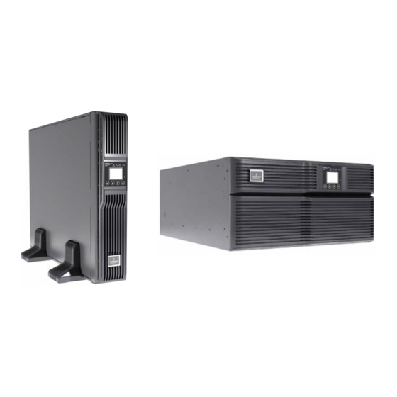
Page 12: Chapter 3 Major Components
Chapter 3 Major Components Chapter 3 Major Components The Liebert® GXT4™ is composed of three major assemblies to provide easier handling, installation and versatility. 3.1 Main Frame and Electronics The cabinet is shipped with internal batteries installed and a basic, hardwire distribution box attached and ready to install. -
Page 13: Removable Power Distribution Box
Chapter 3 Major Components C19 output power receptacles Reserved USB port Output circuit breaker REPO Terminal block communication Maintenance bypass breaker Input circuit External battery breaker connector Output circuit Liebert IntelliSlot breaker port C13 output receptacles Output circuit Knockouts for IT power system breaker hardwired power input... -
Page 14: Internal Battery Packs
Chapter 3 Major Components 3.3 Internal Battery Packs The UPS has two internal battery packs behind a battery access door on the front of the unit. Each internal battery pack is fitted with a connector to link to the UPS. Battery handle Battery connector Front of battery pack... -
Page 15: Chapter 4 What's Included
Chapter 4 What’s Included Chapter 4 What’s Included The Liebert® GXT4™ is shipped with the following items: Terminal Block Communication terminals Compact disc with: Liebert MultiLink® Configuration program & Multi-languages package User manual (electronic version) ... -
Page 16: Chapter 5 Installation And Configuration
Do NOT attempt to start the UPS, turn on any circuit breaker or energize the input power until instructed to do so in 8.2 Initial Startup And Electrical Checks. Visually inspect the UPS for shipping damage. Report any damage to the carrier and your local dealer or Emerson representative. -
Page 17: Rack-Mount Ups Installation
When using the Adjustable Rack Mount Kit, you will use the following instructions. The figures accompanying 5.1.3 Installing Adjustable Rack-Mount Kit—Sold Separately shows the positioning of the rack-mounting brackets. Emerson recommends taking the internal batteries out of the UPS during rack installation. This will make the UPS cabinet lighter and easier to handle. - Page 18 Chapter 5 Installation and Configuration Table 5-1 Included parts in rack-mount kit Item Quantity Rear bracket members Front bracket members Inner bracket members M4 machine screws M4 locking hex nuts M5 machine screws Tools needed for installation are: one Phillips screwdriver ...
- Page 19 Chapter 5 Installation and Configuration Front vertical pole Front member Rear member M5 screw (4 pcs) Figure 5-6 Installing front member of each bracket assembly 6. Get eight M4 screws and eight M4 nuts from the hardware pack in this kit. Each nut has a locking, nylon insert that begins gripping the screw when it is halfway tight.
-
Page 20: External Battery Cabinet Installation
Chapter 5 Installation and Configuration Caution 1. Lifting equipment into the rack may be a two-person job, depending on the weight of the equipment. 2. Liebert® recommends taking the internal batteries out of the UPS during rack installation. This will make the UPS cabinet lighter and easier to handle. - Page 21 Optional rack-mount handles are shipped with the external battery cabinet and may be installed at this time if desired. 3. Securing hardware and slide rails are sold separately. Please contact your local dealer or Emerson representative for these additional options and any assistance needed. Fasten the slides into position with the screws per the instructions included with the slide rails.
-
Page 22: Connect Input/Output Power
Chapter 5 Installation and Configuration 5.3 Connect Input/Output Power Extract these captive screws Extract these captive screws Maintenance bypass breaker Power distribution box removal from 5000VA and 6000VA models Maintenance bypass breaker Power distribution box removal from 10,000VA model Figure 5-11 Power Distribution box removal—captive screws and maintenance bypass breaker The UPS should arrive with the power distribution box attached. - Page 23 Terminal block connections—PD2-CE6HDWRMBS and PD2-CE10HDWRMBS Conduit entry holes are provided on the rear and side of the box. Input and output wiring should not share the same conduit. Emerson recommends using strain relief when installing the wire. Table 5-3 Electrical specifications...
- Page 24 Chapter 5 Installation and Configuration Note 1. The installer must provide circuit breaker protection according to local codes. The utility disconnect should be within sight of the UPS or have appropriate an appropriate lock-out. Maintain service space around the UPS or use flexible conduit. 2.
-
Page 25: Chapter 6 Configuration Program
Chapter 6 Configuration Program Chapter 6 Configuration Program The final step of installation may require custom configuration of your UPS using the enclosed configuration program. Some configuration settings may be changed only while the UPS is off. These should be set before the UPS is put into full-time service powering the critical load. -
Page 26: Chapter 7 Operation And Display Panel
Chapter 7 Operation And Display Panel Chapter 7 Operation And Display Panel This chapter describes the operation and display panel of the Liebert GXT4, including LED indicators, control buttons and LCD display panel. The operation and display panel is on the front panel of the Liebert GXT4 (see Figure 7-1), which provides four control buttons, seven LED indicators and a LCD display panel, as shown in Figure 7-1. -
Page 27: Lcd Display Panel
The operation and display panel provides a LCD display panel, enabling you to view the UPS status and change the UPS settings. 7.3.1 Startup Screen When the UPS is starting up, the UPS begins self-testing, and then the LCD display panel will display EMERSON icon for about 10s, as shown in Figure 7-2. Figure 7-2 Startup screen 7.3.2 ON Screen... -
Page 28: Main Menu Screen
Chapter 7 Operation And Display Panel 7.3.4 Main Menu Screen Press any button in the default screen to enter the Main Menu screen, as shown in Figure 7-6. STATUS CONFIGURATION CONTROL ABOUT Figure 7-6 Main Menu screen To select a submenu, press the UP or DOWN button to move the cursor to the required item, and press the ENTER button to enter its submenu or set its parameter. - Page 29 Chapter 7 Operation And Display Panel AUDIBLE ALARM STARTUP ON BYPASS ENABLE AUTO RESTART GUARANTEE SHUTDOWN PARALLEL FREQUENCY SELECTION VOLTAGE SELECTION AUTO - BYPASS ENABLE TYPE AUTO - BYPASS DISABLE ADDRESS Figure 7-9 UPS screen Press the UP or DOWN button to move the cursor to the required item, and press the ENTER button to confirm the settings.
- Page 30 ENGLISH 中文 Upload others Figure 7-13 LANGUAGE screen 2) Select ‘2 COLOR’ and press the ENTER button to enter the COLOR screen, as shown in Figure 7-14. EMERSON EMERSON EMERSON EMERSON Figure 7-14 COLOR screen 5. FACTORY DEFAULT screen Select Main Menu -> 2 CONFIGURATION -> 7 FACTORY DEFAULT to enter the FACTORY DEFAULT screen, as shown in Figure 7-15.
- Page 31 Chapter 7 Operation And Display Panel Select Main Menu -> 3 CONTROL -> 2 ALARM CONTROL to enter the ALARM CONTROL screen, as shown in Figure 7-18. AUDIBLE ALARM ON AUDIBLE ALARM OFF Figure 7-18 ALARM CONTROL screen 3. BATT TEST screen Select Main Menu ->...
-
Page 32: Prompt List
Chapter 7 Operation And Display Panel Figure 7-23 ABOUT screen The ABOUT screen displays: UPS model, SN, software version and hardware version. Menu structure The menu structure of the LCD display panel is shown in Figure 7-24. Figure 7-24 Menu structure 7.3.5 Prompt List A prompt screen is displayed during the operation of the system to alert you to certain conditions and/or to require your confirmation of a command or other operation. -
Page 33: Warning List
Chapter 7 Operation And Display Panel Table 7-4 Prompts and meanings Prompt Meanings The utility power recovers, and the UPS transfers back to Utility (AC) Utility power restored mode The bypass power recovers, and the UPS can transfers back to Bypass power restored bypass UPS return from a low battery condition... -
Page 34: Fault List
Chapter 7 Operation And Display Panel 7.3.7 Fault List All UPS fault messages are described in Table 7-5. Table 7-6 Fault list Fault Description UPS self test failed The battery is bad or weak PFC Out of Order PFCfailure occurs UPS overload The UPS is overloaded Inverter Out of Order... -
Page 35: Chapter 8 Operation
Chapter 8 Operation Chapter 8 Operation This section describes checks to be made before starting the UPS, how to start the UPS, manual battery test, manual bypass, shutting down the UPS and disconnecting the utility power from the UPS. Note The Liebert®... -
Page 36: Shut Down Liebert Gxt4
Chapter 8 Operation 8.5 Shut Down Liebert GXT4 Select Main Menu -> 3 CONTROL -> 1 TURN ON & OFF to enter the TURN ON & OFF screen, and select ‘TURN UPS OFF’ to turn off the UPS. 8.6 Disconnecting Input Power From Liebert GXT4 1. - Page 37 Chapter 8 Operation IT power system connectors IT power system connectors 10,000VA model 5000VA and 6000VA models Figure 8-2 Disconnecting the connectors 3. Install IT Power System Access Cover and screws. Liebert GXT4 UPS 5000VA ~ 10000VA (230V) User Manual...
-
Page 38: Chapter 9 Communication
Chapter 9 Communication Chapter 9 Communication This chapter introduces communication of the Liebert® GXT4™ UPS, including communication interface port, terminal block, Liebert IntelliSlot® communication cards and remote emergency power off. 9.1 Communication Interface Port The Liebert® GXT4™ UPS has a terminal block on the rear of the UPS unit. Several signals are provided on this port and are assigned as follows. -
Page 39: On Battery
Liebert MultiLink when you purchase a Liebert MultiLink License Kit. For more information about the Liebert IntelliSlot SNMP/Web Card and Liebert MultiLink License Kits, visit our Web site (www.liebert.com) or contact your local dealer or Emerson representative. -
Page 40: Remote Emergency Power Off
Chapter 9 Communication Liebert IntelliSlot SNMP/Web Card provides SNMP and Web-based monitoring and control of the UPS across the network. The Liebert IntelliSlot MultiPort 4 Card allows installing Liebert MultiLink software on four computers and coordinate shutdown in the event of a power failure. The Liebert IntelliSlot Relay Card provides dry contact relay outputs for custom wired applications and delivers support for built-in shutdown for AS/400 systems. -
Page 41: Chapter 10 Maintenance
The Liebert GXT4™ is designed to allow the user to replace the internal battery pack safely. Read the safety cautions before proceeding. Contact your local dealer or Emerson representative to obtain the part number and pricing of the appropriate replacement battery pack. - Page 42 Compare the new and old internal battery packs to make sure they are the same type and model. If they are the same, proceed with Step 7; if they are different, stop and contact your local Emerson representative or Emerson Channel Support.
-
Page 43: Battery Charging
Liebert® GXT4™ charges the batteries continuously when it is connected to the utility input power. If the Liebert GXT4 will be stored for a long time, Emerson recommends connecting the UPS to input power for at least 24 hours every four to six months to ensure full recharge of the batteries. -
Page 44: Chapter 11 Specifications
Chapter 11 Specifications Chapter 11 Specifications Table 11-1 UPS specifications Product model GXT4-5000RT230 GXT4-6000RT230 GXT4-10000RT230 Parameters GXT4-5000RT230E GXT4-6000RT230E GXT4-10000RT230E 4000W/5000VA 4800W/6000VA 9000W/10000VA Dimensions, Rack Mount, W x D x H Unit, mm (in) 430 × 574 × 217 (16.9 × 22.4 × 8.5) 430 ×... - Page 45 Chapter 11 Specifications Product model GXT4-5000RT230 GXT4-6000RT230 GXT4-10000RT230 Parameters GXT4-5000RT230E GXT4-6000RT230E GXT4-10000RT230E 4000W/5000VA 4800W/6000VA 9000W/10000VA Agency Safety IEC62040-1:2008 version, GS mark EMI/EMC/C-Tick EMC IEC/EN/AS 62040-2 2nd Ed (Cat 2 – Table 6) IEC/EN EN61000-4-2, Level 4, Criteria A Radiated Susceptibility IEC/EN EN61000-4-3, Level 3, Criteria A Electrical Fast Transient IEC/EN EN61000-4-4, Level 4, Criteria A...
- Page 46 Chapter 11 Specifications Table 11-5 Battery run time 230VAC RT Models Number of batteries Load 5000VA 6000VA 10000VA Internal battery 100% Internal battery + 1 external battery cabinet 100% Internal battery + 2 external battery cabinets 100% Internal battery + 3 external battery cabinets 100% 1208...
- Page 47 Chapter 11 Specifications 230VAC RT Models Number of batteries Load 5000VA 6000VA 10000VA 1427 1340 Internal battery + 5 external battery cabinets 100% 1574 1500 1091 1021 Internal battery + 6 external battery cabinets 100% Using the configuration program, the user may specify the number of external battery cabinets attached to the UPS. The factory default is programmed for internal batteries only.
-
Page 48: Chapter 12 Product Warranty Registration
To register for warranty protection, visit the Quick Links section of the Liebert Web site at: http://www.liebert.com Click on Product Warranty Registration and fill in the form. If you have any questions, contact Emerson Channel Support at: North America: 800-222-5877 Outside North America: 00-800-1155-4499... - Page 50 Network Power service technicians. While every precaution has been taken to ensure the accuracy and completeness of this literature, Emerson Network Power assumes no responsibility and disclaims all liability for damages resulting from use of this information or for any errors or omissions.
Need help?
Do you have a question about the Liebert GXT4-5000RT230 and is the answer not in the manual?
Questions and answers