Waldorf RN8510G Installation And Operation Manual
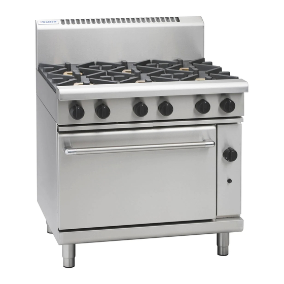
800 series gas range static oven
Hide thumbs
Also See for RN8510G:
- Installation and operation manual (28 pages) ,
- Installation and operation manual (27 pages) ,
- Installation and operation manual (28 pages)
Table of Contents

Related Manuals for Waldorf RN8510G


Summary of Contents for Waldorf RN8510G
- Page 1 I n s t a l l a t i o n a n d O p e r a t i o n M a n u a l Gas Range Static Oven Series RNL8510G RN8510G RNL8610G RN8610G RN8810G...
- Page 2 MANUFACTURED BY Moffat Limited PO Box 10001 Christchurch New Zealand (03) 389 1007 Fax: (03) 389 1276 WORLD-WIDE BRANCHES UNITED KINGDOM Blue Seal 67 Gravelly Business Park Gravelly Park Birmingham West Midlands B24 8TQ (121) 327 5575 Fax: (121) 327 9711 UNITED STATES Moffat Inc 3765 Champion Blvd...
-
Page 3: Table Of Contents
Contents List Waldorf Gas Static Oven Range RN(L)8510G Gas Range Static Oven - 750 mm wide. RN(L)8610G Gas Range Static Oven - 900 mm wide. RN(L)8810G Gas Range Static Oven - 1200 mm wide. Introduction ....................2 Specification ....................3... -
Page 4: Introduction
Introduction We are confident that you will be delighted with your WALDORF GAS RANGE STATIC OVEN and it will become a most valued appliance in your commercial kitchen. To ensure you receive the utmost benefit from your new Waldorf appliance, there are two important things you can do. -
Page 5: Specification
Specifications Model Numbers Covered in this Specification RN[1]8510G [2] Gas Range Static Oven, 4 Open Burners. RN[1]8513G [2] Gas Range Static Oven, 2 Open Burners, 300mm Griddle. RN[1]8610G [2] Gas Range Static Oven, 6 Open Burners. RN[1]8613G [2] Gas Range Static Oven, 4 Open Burners, 300mm Griddle. RN[1]8616G [2] Gas Range Static Oven, 2 Open Burners, 600mm Griddle. -
Page 6: Gas Supply Requirements
Specifications Gas Supply Requirements - Non - CE Only: Natural Gas LP Gas (Propane) Input Rate (N.H.G.C.) 28 MJ/hr 28 MJ/hr - each Open Burner (26,540 Btu/hr) (26,540 Btu/hr) - each 300 mm Griddle Section 21 MJ/hr 21 MJ/hr (19,900 Btu/hr) (19,900 Btu/hr) - Oven 30 MJ/hr... -
Page 7: Dimensions
Dimensions RN(L)8510G Cook Top Options RN(L)8510G RN(L)8513G... - Page 8 Dimensions RN(L)8610G Cook Top Options RN(L)8610G RN(L)8613G RN(L)8619G RN(L)8616G...
- Page 9 Dimensions RN(L)8810G Cook Top Options RN(L)8810G RN(L)8813G RN(L)8816G RN(L)8819G...
-
Page 10: Installation
Waldorf Gas Range Static Ovens are designed to provide years of satisfactory service, and correct installation is essential to achieve the best performance, efficiency and trouble-free operation. -
Page 11: Clearances
Gas Connection NOTE: ALL GAS FITTING MUST ONLY BE CARRIED OUT BY AN QUALIFIED PERSON. Waldorf Gas Range Static Ovens do not require an electrical connection, as they function totally on the gas supply only. It is essential that the gas supply is correct for the appliance to be installed and that adequate supply pressure and volume are available. - Page 12 Installation The regulator connections are " BSP female. The connection to the appliance is " BSP male. (Refer to the “Specifications” section for the gas supply location dimensions). NOTE: A Manual Isolation Valve must be fitted to the individual appliance supply line. Correctly locate the appliance into its final operating position and using a spirit level, adjust the legs so that the appliance is level and at the correct height.
-
Page 13: Operation
/ operator. Waldorf appliances have been designed to provide simplicity of operation and 100% safety protection. Improper operation is therefore almost impossible, however bad operation practices can reduce the life of the appliance and produce a poor quality product. To use this appliance correctly please read the following sections carefully:- •... -
Page 14: Open Burners
Operation Open Burners NOTE: Only cooking pans from size Ø 150mm to Ø 420mm are suitable fo use on these open burners. Flame Failure Option (F-Models) Lighting the Open Burners Flame Failure Protection is incorporated for each burner by way of a thermo-electric system which will shut off the gas supply to that burner in the event that the burner goes out, so that un-burnt gas is not expelled. -
Page 15: Griddle
Operation Griddle AUTIO N The griddle plate temperature reaches over 300°C in hottest points during normal operation at 'Full Flame' setting. Lighting the Griddle a. Depress the gas control knob and rotate anti-clockwise to the ‘PILOT’ position. b. With the gas control knob depressed, press the piezo ignition button to ignite the pilot burner. Repeat Items 1 to 2 until the pilot is lit. -
Page 16: Lighting The Oven Pilot Burner
Operation Lighting the Oven Pilot Burner Pilot Burner viewing holes ! IMPORTANT DO NOT USE aluminium foil or trays directly on the cast iron sole plate(s). NEVER block or cover the openings on each side of the sole plate(s). This oven is fitted with a pilot as a standard option and flame failure protection, which is incorporated by way of a thermo-electric system for the main burner. -
Page 17: Oven 'Shut Down
Operation Control Knob in Oven ‘Shut-Down’ ’Off’ Position NOTE: DO NOT attempt to rotate the Thermostat Control Knob anti-clockwise back to the ‘O’ Off position as the Knob and Gas Valve will be damaged. partially depress To turn 'Off' the oven completely, thermostat control knob whilst turning clockwise to the 'O' Off position, the pilot burner will extinguish. -
Page 18: Cleaning And Maintenance
Cleaning and Maintenance AUTIO N Always turn off the gas supply before cleaning. This appliance is not water proof. Do not use water jet spray to clean interior or exterior of this appliance. General Clean the range regularly. A clean range looks better, will last longer and will perform better. Carbonised grease on the surface or between the trivets, griddle plates will hinder the transfer of heat from the cooking surface to the food. -
Page 19: Daily Cleaning
Cleaning and Maintenance Daily Cleaning The grease / spill tray(s) should be checked and emptied frequently to prevent overflow and spillage. Remove the grease / spill tray(s) while still warm so that the grease is in a liquid state. Empty any grease from the trays and wash thoroughly in the same manner as any cooking utensil. Remove the burner caps and bases, the trivets and thoroughly clean the splash back, interior and exterior surfaces of the range with hot water, a detergent solution and a soft scrubbing brush. - Page 20 Cleaning and Maintenance Trivets and Burners Burner Cap a. Remove the trivets from the top of the appliance, taking note that the trivets are manufactured with a lip on one edge, the lip must always be fitted to the outer edge (front and back) of the cook top. (Refer to Fig 10 overleaf).
-
Page 21: Periodic Maintenance
Cleaning and Maintenance Notice Lip on NOTE: It is imperative that the trivet supports are correctly Trivet Edge re-fitted to the appliance to ensure that the trivets locate correctly and sit flush and level. NOTE that the trivet support front end, side rail profiles are different at either side (See Fig 6) and only one of the side rails... -
Page 22: Fault Finding
Fault Finding This section provides an easy reference guide to the more common problems that may occur during the operation of your appliance. The fault finding guide in this section is intended to help you correct, or at least accurately diagnose problems with your equipment. Although this section covers the most common problems reported, you may encounter a problem not covered in this section. -
Page 23: Gas Conversion And Specifications
Gas Conversion and Specifications Conversion Procedure AUTIO N Ensure that the appliance is isolated from the gas supply before commencing servicing. Burner NOTE: • These conversions should only be carried out by qualified persons. All connections must be checked for leaks before re-commissioning the appliance. - Page 24 Gas Conversion and Specifications Notice Lip on Refit all the trivet supports to the top of the appliance. Note Trivet Edge the orientation of the trivet support when re-fitting as the front end side rail profiles are different from the rear end side rail profiles.
- Page 25 Gas Conversion and Specifications Pilot Injectors a. Unscrew and remove the Pilot Injector Plug from the fitting at the end of the pilot injector tube using a 11 mm A/F Pilot Injector Housing spanner. (Refer to Fig 23). b. Using a flat bladed screwdriver, unscrew and remove the pilot injector from the pilot injector housing.
- Page 26 Gas Conversion and Specifications Griddle Pilot Burner a. With the gas supply turned off at the main supply, Gas Control remove the griddle plate section by lifting it Heat Shield straight off the cook top. b. Remove the gas control heat shield from around the griddle burner, this is just a push in fit.
- Page 27 Gas Conversion and Specifications Shown with door removed for ease of viewing Oven Injector: a. With the gas supply turned off at the main supply, unscrew and remove the 6 screws securing the lower lintel to the front of the oven. (See Fig 30).
-
Page 28: Gas Regulator
Gas Conversion and Specifications Gas Regulator NOTE: The regulator supplied is convertible between Natural Gas and LPG, but it’s outlet pressure is fixed ex-factory and is NOT to be adjusted. NOTE, Pin rotated for Natural Gas NOTE, Pin rotated for LPG Fig 34 Ensure that the gas supply is turned ‘OFF’... -
Page 29: Gas Specifications
Gas Conversion and Specifications Gas Specifications - Australia / New Zealand Only: Natural. Gas LP Gas (Propane) Main Burner Injectors Ø 2.45 mm Ø 1.50 mm Open Burner Pilot Burner ('PF' Option Only) 0.30 0.20 Main Burner Ø 2.10 mm Ø... -
Page 30: Replacement Parts List
Replacement Parts List Replacement Parts List IMPORTANT: Only genuine authorized replacement parts should be used for the servicing and repair of this appliance. The instructions supplied with the parts should be followed when replacing components. For further information and servicing instructions, contact your nearest authorized service branch (contact details are as shown on the reverse of the front cover of this manual). - Page 31 Oven Rack (RN8510G). 227896 Oven Rack (RN8610G - RN8810G). General 227015 Pot Stand / Trivet. 228884 Spill Tray (750mm - RN8510G Series). 228883 Spill Tray (450mm - RN8610G Series). 228882 Spill Tray (600mm - RN8810G Series). 229674 Rear Roller Assy. 227850 Adjustable Leg (150mm).
Need help?
Do you have a question about the RN8510G and is the answer not in the manual?
Questions and answers