Table of Contents
Advertisement
Quick Links
Advertisement
Table of Contents

Related Manuals for Elation Power Spot 575IE II


Summary of Contents for Elation Power Spot 575IE II
- Page 1 User Manual S o ftw a re V e rs io n 1 .1 7 Re v is e d...
- Page 2 Power Spot 575IE II™ 2 /2 6 /2 0 0 8 ©Elation Professionals® Los Angeles, Ca. wwww.ElationLighting.com Page...
-
Page 3: Table Of Contents
Power Spot 575IE II™ CONTENTS General Information……………………………………………………………………… 3 a. Introduction………………………………………………………………………. 3 b. Unpacking………………………………………………………..…………..….. 3 c. Customer Support…………………………………………….………………… 3 d. Warranty Registration……………………………………………………..……. 4 e. Discharge Lamp Warning……………………………………………………….4 Safety Instructions………………………………………………………..…………. 7 Fixture Layout………………………………………………………………………..8 Mounting and Installation………………………………………………………….……. 11 a. Mounting Positions……………………………………………………………… 11 b. -
Page 4: General Information
INTRODUCTION: Congratulations, you have just purchased one of the most innovative and reliable lighting fixtures on the market today! The Power Spot 575IE II,™ has been designed to perform reliably for years when the guidelines in this booklet are followed. -
Page 5: Warranty Registration
Please do not discard the shipping carton in the trash. Please recycle whenever possible. WARRANTY REGISTRATION: The Power Spot 575IE II™ carries a two year (730 days) limited warranty. Please fill out the enclosed warranty card to validate your purchase. All returned service items whether under warranty or not, must be freight pre-paid and accompany a return authorization (R.A.) number. - Page 6 Power Spot 575IE II™ life and intensity. To achieve the intensity associated with discharge lamps, these lamps use a gas sealed in a high-pressure environment to emit a brilliant output. Due to the high pressure involved with the construction of the lamp, the lamp may explode during prolonged extensive use.
-
Page 7: Safety Instructions
2. Never touch the fixture during normal operation. This can cause severe personal injuries and/or damage to the fixture. 3. Be sure to unplug the Power Spot 575IE II™ from the power outlet before performing any service related issues. 4. Lamp Replacement; Allow at least 30 minutes after disconnecting main power before you open the Power Spot 575IE II™. - Page 8 Power Spot 575IE II™ fixture. Any structural modification will void the original manufactures warranty and may increase the risk of damage and/or personal injury. 10. To reduce the risk of fire or shock, do not expose this fixture to rain or moisture.
-
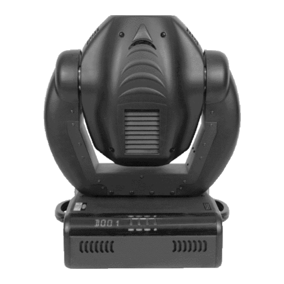
Page 9: Fixture Layout
Power Spot 575IE II™ 3. Fixture Layout 1. Lens Assembly 2. DMX Input Jack 3. DMX Output Jack 4. Microphone Sensitivity Adjustment Knob 5. Firmware Connection 6. Internal Cooling Fan 7. Base 8. Retaining Arm 9. Lamp Fuse Holder 10. Electronics Fuse Holder 11. - Page 10 Power Spot 575IE II™ 1. Lens Assembly - This high quality lens is a fully focusing. Focus the lens by manually turning the lens in a clockwise or counter-clockwise direction until the desired effect is achieved. 2. DMX Input Jack – This 3-Pin XLR jack is used to receive an incoming DMX signal.
- Page 11 Power Spot 575IE II™ fuse with an exact match unless otherwise instructed by an authorized Elation technician. 11. Powercon Connector – This power jack is designed to be used only with the Neutrik Powercon adapter included with your fixture. This jack provides main power to your fixture.
-
Page 12: Mounting And Installation
Power Spot 575IE II™ 4. MOUNTING AND INSTALLATION Mounting The POWER SPOT 575IE™ is fully operational in two different mounting positions, hanging upside from a ceiling or set on a flat level surface. To avoid internal damage to the unit, never mount the unit on its side as illustrated below. -
Page 13: Mounting Points
4x M10x20mm 4x Camlock Secure the POWER SPOT 575IE II™ Regardless of the rigging option you choose for your P O WE R S P O T 575IE II™ always be sure to secure your fixture with a safety cable. The fixture provides a built-in rigging point for a safety cable on the underside of the fixture, be sure to use this point and never secure a safety cable to a carrying handle. - Page 14 Power Spot 575IE II™ Connections P ower s upply • Electronic ballast with: 90~260 Volts, 50~60 Hz, • Grounded contact type plug – Neutrik Powercon • Connected load 780W <=> 3.8A (blind current compensation). NOTE: The universal power supply will accept any voltage source as detailed above without any type of internal or user modifications.
-
Page 15: Understanding Dmx
1 to that fixture no matter where it is located in the DMX chain. The Power Spot 575IE II™ can be controlled via DMX-512 protocol. The Power Spot 575IE II™ is a 16-channel DMX fixture. The DMX address is set electronically using the controls on the LCD menu. -
Page 16: Dmx Terminator
Power Spot 575IE II™ Be sure to follow the above figure when making your own cables. Do not use the ground lug on the XLR connector. Do not connect the cable’s shield conductor to the ground lug or allow the shield conductor to come in contact with the XLR’s outer casing. -
Page 17: 3-Pin To 5-Pin Conversion
Power Spot 575IE II™ 5-Pin XLR DMX Connectors. Some manufactures use 5-pin XLR connectors for DATA transmission in place of 3-pin. 5-pin XLR fixtures may be implemented in a 3-pin XLR DMX line. When inserting standard 5-pin XLR connectors in to a 3-pin line a cable adaptor must be used, these adaptors are readily available at most electric stores. - Page 18 Power Spot 575IE II™ In the case of the Power Spot 575IE II™, which is a 16 channel fixture, you should set the starting DMX address of the first unit to 1, the second unit to 17 (16 + 1), the third unit to 33 (16 + 17), and so on.
-
Page 19: Fixture Menu
Power Spot 575IE II™ 6. FIXTURE MENU The control panel located on the side of the fixture allows you to access the main menu and make all necessary adjustments to the POWER SPOT 575IE II™. During normal operation, tapping the “MODE” key once will access the fixture’s main menu. -
Page 20: Menu Functions
Power Spot 575IE II™ clre Clears internal memory (technician only) ares Adjust Reset (wheels static after reset) VTIL Software version, tilt pc-board VTR1 Software version, driver board 1 VTR2 Software version, driver board 2 VTR3 Software version, driver board 3... - Page 21 Power Spot 575IE II™ The A udio P rogram Audi The A udio menu allows you to run a stand-alone audio program. This program can AFST Aslw AFST run either fast ( ) or slow ( ); Fast ( ): When running in “fast” mode Aslw every sound impulse will trigger a new step.
- Page 22 Power Spot 575IE II™ This function will rest and return all motors to the home position. Access the reset function in the main menu and press the Enter button to engage the reset function will readout in the display). 6.6 R unning Tim e (lam p/unit) TIME This menu function will read out three different fixture running times.
- Page 23 Power Spot 575IE II™ SPEC S P O T 575IE ™ . The sub-menu consists of several sub-menus. Navigation details of the special functions and their sub-menus are as followed: 6.9.1 Manual D riv e MANU This feature allows you to drive all the unit’s functions manually for use in an environment that requires a static position (no movements), determining focus points, or testing.
- Page 24 Power Spot 575IE II™ 6.9.3 Lam p O ff v ia D MX DLOF This function allows the lamp to be switched off through a DMX controller. To enable this function use the U p and D own buttons to toggle between .
- Page 25 Power Spot 575IE II™ Use this function to choose between different display indications. Use the Up/Down-keys to select desired function and press Enter to confirm or Mode to cancel and return to the menu. D ON Display On/Off (If you've chosen , the display will go out within 15 seconds after the last input.
- Page 26 Power Spot 575IE II™ speed. When the maximum internal intolerable operating temperature is reached the lamp will automatically shut off. In this setting the fan will operate at the lowest speed. When the LOHI maximum internal intolerable operating temperature is reached the fan will automatically switch from low to high speed.
- Page 27 Power Spot 575IE II™ DFSE This function is used to restore all the factory default settings and presets. Press the E nter button to confirm this operation or the Mode button to cancel and return to the menu. When this operation is selected the LED will briefly readout , then return to the previous function.
- Page 28 Power Spot 575IE II™ after having switched off (lamp too hot). The message will appear on the display if the lamp doesn’t ignite within 20 seconds. The fixture will store this command and automatically ignite the lamp after 5 minutes.
-
Page 29: Operation
DMX controller allows you to create unique programs tailored to your individual needs. The Power Spot 575IE II™ uses 16 DMX channels. See page 27 for detailed description of the DMX traits.To control your fixture in DMX mode, follow the set-up procedures on pages 13-15 as well as the set-up specifications that are included with your DMX controller. - Page 30 Power Spot 575IE II™ • Be sure the Master (MSTR) function is switched “ON,“ and the SVPT function is switched “OFF.“ • Choose your room size. The size function allows you to choose a the approximate size of the room (NORM, BIG, MIDL, SMAL). The built-in programs will automatically adjust to your slection to optimize light output for your room.
-
Page 31: Dmx Channel Values
Power Spot 575IE II™ 8. DMX CHANNEL SELECTION (DMX PROTOCOL) P ower S pot 575IE D MX C hannel S elec tion Channel Function Time and Value 1) PAN- 0 .. 530° min. 2,65 s 0..255 00..FF 0..100 coarse 2) PAN-fine High- Pos ... - Page 32 Power Spot 575IE II™ Channel Function Time and Value color 4 / color 5 (slow) 82..83 52..53 32,4 color 5, Pink (slow) 84..85 54..55 33,1 color 5 / color 6 (slow) 86..87 56..57 33,9 color 6, Orange (slow) 88..89 58..59...
- Page 33 Power Spot 575IE II™ Channel Function Time and Value Gobo rotation, fast-slow, CCW max. 1.0 turns/sec. 192..253 C0..F 76..98 Audio gobo chase, slow each 4 sound impulse new gobo each sound impulse Audio gobo chase, fast new gobo 7) Gobo 1 Gobo position 0 ...
- Page 34 Power Spot 575IE II™ Channel Function Time and Value Strobe effect , slow - fast max. frequent 10 Hz 48..239 30..EF 13..93 Shutter open (lamp start) 240..255 F0..FF 94..100 10) Dimmer Dimmer closed (0%) 0..3 0..3 0..1 Dimmer 1%...99% movement time 0,3 4..251...
- Page 35 Power Spot 575IE II™ Channel Function Time and Value No function 208..223 D0..D 82..87 Fan on min. as long as temp. < 90°C 224..229 E0..E 88..90 Lamp OFF (min. 3 sec.) 230..249 E6..F9 92..97 Reset 250..255 FA..FF 98..100 15) Movement...
-
Page 36: Lamp Replacement
Power Spot 575IE II™ 9. LAMP REPLACEMENT For a proper and safe lamp change, please read this chapter carefully and follow all instructions. 9.1 S afety R egulations • Pull out the main plug! • Wait min. 20 minutes after the last operation to cool down the fixture. - Page 37 Power Spot 575IE II™ to head. Carefully pull back the socket assembly. Gently remove the old lamp from it’s socket. If the old lamp has exploded be sure to remove all of the old lamp fragments to prevent damage to the internal components.
-
Page 38: Fuse Replacement
Power Spot 575IE II™ 10. FUSE REPLACEMENT Caution: Always replace with the exact same type fuse, unless otherwise specified by an authorized Elation service technician. Replacing with anything other than the specified ® part can damage your unit and will void your manufactures warranty. -
Page 39: Replacing Gobos
Power Spot 575IE II™ 11. CHANGING/REPLACING GOBOS The POWER SPOT 575IE II™ is fitted with a standard size gobo wheel that accepts gobos with an outside diameter of 26.9mm and a viewable image size of 23mm. Glass or steel gobos may be used. Please follow the safety procedures and installation below for proper and pain gobo exchange. - Page 40 Power Spot 575IE II™ Special Notice: If you use glass gobos, the non-vaporized side must be fitted towards the lamp direction. ©Elation Professionals® Los Angeles, Ca. wwww.ElationLighting.com Page...
-
Page 41: Maintance And Cleaning
Power Spot 575IE II™ 12. Maintenance and Cleaning It is absolutely essential that the fixture is kept clean and dust, dirt and smoke-fluid residues do not built-up on the surface or within the fixture. Residue build-up may cause the fixture's light output to be significantly reduced. Regular cleaning will not only ensure the maximum light output, but will also allow the fixture to function reliable throughout its life. - Page 42 Power Spot 575IE II™ The above chart is a recommended cleaning schedule only. Cleaning frequency depends on the environment in which the fixture operates (I.E. smoke, fog residue, dust, dew). In clubs that observe heavier use, we recommend cleaning on a more frequent basis.
-
Page 43: Technical Specifications
Power Spot 575IE II™ 13. TECHNICAL SPECIFICATION Power supply Power consumption 90~260V, 50~60 Hz 780 Watt, 3.8A, electronic ballast, (blind current compensated) Fuse protection Lamp: 8A/250V, GMA (5x20mm fine-wire fuse) Electronic: 1A/250V, GMA (5x20mm fine-wire fuse) Lamp Type HTI 575-DE (OSRAM) -
Page 44: Warranty
Power Spot 575IE II™ 14. 2 YEAR (730 DAYS) LIMITED WARRANTY A. Elation Professionals hereby warrants, to the original purchaser, Elation ® Professionals products to be free of manufacturing defects in material and workmanship ® for a period of two years (730 days) from the date of purchase. This warranty shall be valid only if the product is purchased within the United States of America, including possessions and territories. -
Page 45: Elation Professionals® Los Angeles, Ca. - Wwww.elationlighting.com
Power Spot 575IE II™ improvements upon its products without any obligation to include these changes in any products theretofore manufactured. F. No warranty, whether expressed or implied, is given or made with respect to any accessory supplied with products described above. Except to the extent prohibited by... -
Page 46: Dimensional Drawings
Power Spot 575IE II™ 15. DIMENSIONS ©Elation Professionals® Los Angeles, Ca. wwww.ElationLighting.com Page... - Page 47 Power Spot 575IE II™ Laser Warning Labels: When installing this fixture be sure that it is mounted in a manner that prevents the audience from directly into the laser beam. Be sure the fixture is mounted in manner that prevents the laser beam from sticking the audience.
- Page 48 Power Spot 575IE II™ ©Elation Professionals® Los Angeles, Ca. wwww.ElationLighting.com Page...
- Page 49 Power Spot 575IE II™ Elation Professional 4295 Charter Street Los Angeles, CA. 90058 323-582-3322 / 323-582-3108 fax ©Elation Professionals® Los Angeles, Ca. wwww.ElationLighting.com Page...
- Page 50 Power Spot 575IE II™ www.ElationLighting.com / info@ElationLighitng.com ©Elation Professionals® Los Angeles, Ca. wwww.ElationLighting.com Page...
Need help?
Do you have a question about the Power Spot 575IE II and is the answer not in the manual?
Questions and answers