
Related Manuals for Revolabs 01-4FUSIONEU-NM


Summary of Contents for Revolabs 01-4FUSIONEU-NM
- Page 1 Revolabs Fusion™ Wireless Microphone System Installation and User’s Guide Microphones must be fully charged and paired to the Charger Base prior to first use. Rev 1.1...
- Page 2 Model Numbers: 01-8FUSIONEU-NM Revolabs Fusion Base Station, European 01-4FUSIONEU-NM Revolabs Fusion Base Station, European 01-8FUSIONEU-62 Revolabs Fusion System with 6 tabletop omni’s & 2 wearable mics, European 01-4FUSIONEU-31 Revolabs Fusion Base System with 3 tabletop omni’s & 1 wearable mics, European 03-EXEMICEU-BLK-11 Revolabs Solo™...
- Page 3 IC: 6455A-01EXEMIC Revolabs Solo™ Executive Microphone Video Conferencing Revolabs Fusion Wireless Microphone Solution includes all of the necessary cables to plug into any of the major video-conferencing RESTRICTED USE WITH CERTAIN MEDICAL DEVICES solutions, including Lifesize, Polycom, Sony and Tandberg. It...
- Page 4 Installation Guide Revolabs Fusion™ Contents of box: NOTE: This equipment has been tested and found to comply with the limits Fusion Base Station, Fusion Base for a Class B digital device, pursuant to part 15 of the FCC Rules. These limits...
- Page 5 Safety and General Information Plug Cable A (single RCA to double RCA) single RCA connector into Fusion Please read the following information to ensure safe use of your Revolabs Base Station <Room Out> RCA port, and then plug the double RCA connectors system.
- Page 6 1.88 to 1.90 GHz (DECT EU) Connectors: Fusion Base Station IR Remote Serial DB9 CD Programming Serial DB9 - for Revolabs use only Audio Control RJ45 – for Revolabs use only Telephone Line-In RJ11 Telephone Set-In RJ11 Network RJ45 – for Revolabs use only...
- Page 7 Revolabs Fusion™ Warranty Revolabs, Inc. warrants this product to be free of manufacturing defects. Repair or replacement of any defective part or unit (at the discretion of the Seller) will be free of charge for the period of one year.
- Page 8 Revolabs Fusion™ Installation Guide Polycom Installation Plug red RCA connector of Cable C, the double RCA to double RCA cable, Station Meaning into the Fusion Base Station <Conf Out>, then plug the other end red RCA nel LEDs connector into the Polycom video-station <Conf In>. Plug black RCA connector Charging in Progress of Cable C, into the Fusion Base Station <Conf In>, and the other black RCA...
- Page 9 Installation Guide Revolabs Fusion™ Revolabs Solo™ Indicator LED Equipment Use Microphone LED Base S Chann Microphone in Charger Solid RED Base Solid GREEN* Microphone not in Charger Base Two RED flashes every RED F 1.5 seconds GREEN flash every 1.5...
- Page 10 Installation Guide Revolabs Fusion™ SONY INSTALLATION Requires special cable of XLR connector to 3.5 mm phono connector. The Adapter does not provide phantom power or bias current so it cannot be used with condenser or electret microphones. With the microphone attached, un-mute the Adapter by pressing and releasing the Mute button (confirm by viewing flashing GREEN LED).
- Page 11 Installation Guide Revolabs Fusion™ Using the Solo XLR Microphone Wireless Adapter The Revolabs Solo™ Universal Wireless Adapter for Handheld Microphones, shown in the following figure, is connected to your existing handheld dynamic microphones for wireless freedom during open microphone meetings, Q&A sessions, classrooms, etc.
- Page 12 Installation Guide Revolabs Fusion™ • Tandberg Installation TableTop microphones should be centered on the table with the integral grill pointed toward the users (uni-directional), or centrally located between users (omni-directional), from 2 to 5 feet (.75 to 1.75m) away. It...
- Page 13 Adjust the audio Input Type Level if necessary. To use the Revolabs Solo™ TableTop Microphone: Speak into the Revolabs microphones that are connected to the audio line inputs. Remove the microphone from the Charger Base to turn on and automatically...
- Page 14 Installation Guide Revolabs Fusion™ Revolabs Solo™ Wearable Microphones turn on and mute automatically when Pairing Wireless Microphones to Fusion removed from Charger Base, to reduce noise while being attached. The microphone has a clip on the back which allows the microphone to be easily Base Station attached onto a shirt pocket, blouse, lapel or lanyard.
- Page 15 Using Revolabs Solo™ Wearable Wireless Microphone The Fusion Base Station has four or eight indicator LEDs (one for each The Revolabs Solo™ Wearable Microphones, shown in the following figure, are microphone) and pairing push buttons on the front panel. When the LED is paired to the Base Station and can be worn on the user’s shirt pocket, lapel or...
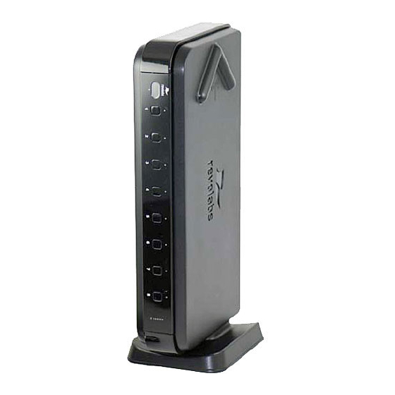
- Page 16 Charger Base. It is important to ensure that the system microphones are The Revolabs Fusion Base Station, shown below in front and rear panel inserted fully in the base so that charging will occur. Features of the base are views, manages wireless audio signal processing, and pairing between the shown in the following figure.
- Page 17 Telephone Line-in RJ11 Telephone Set-in RJ11 Audio Control RJ45 (Revolabs use only) Programming Port: LEFT DIP Switches 1-8 (refer to page x) Programming Port: RIGHT DIP Switches 1-8 (Revolabs Use Only) 10. IR Remote 11. DB9 (Revolabs use only) Page 22...
- Page 18 (default no tabletop master mute) and switch 6 for Auto Answer (default off). Programming Port (#9, page 17) on the right is reserved for Revolabs Use Only. To answer a phone call and begin a teleconference, the user must use the Remote Control and press the “answer”...
- Page 19 Installation Guide Revolabs Fusion™ Programming Ports DIP Switch Used for Programming Port Settings for Multiple Muting Option Fusion Systems Setting the Mute Option There are two settings that must be adjusted when more than one Fusion system is used within a 100’ (30.5 m) foot range: frequency and transmit power Individual Muting (default) level.
Need help?
Do you have a question about the 01-4FUSIONEU-NM and is the answer not in the manual?
Questions and answers