
Related Manuals for Grizzly G0709


Summary of Contents for Grizzly G0709
- Page 1 MODEL G0709 14" x 40" GUNSMITHING LATHE OWNER'S MANUAL WARNING: NO PORTION OF THIS MANUAL MAY BE REPRODUCED IN ANY SHAPE OR FORM WITHOUT THE WRITTEN APPROVAL OF GRIZZLY INDUSTRIAL, INC.
- Page 2 This manual provides critical safety instructions on the proper setup, operation, maintenance, and service of this machine/tool. Save this document, refer to it often, and use it to instruct other operators. Failure to read, understand and follow the instructions in this manual may result in fire or serious personal injury—including amputation, electrocution, or death.
-
Page 3: Table Of Contents
INTRODUCTION ... 2 SECTION 1: SAFETY ... 7 SECTION 2: POWER SUPPLY ... 10 SECTION 3: SETUP ... 12 SECTION 4: OPERATION ... 23 SECTION 5: ACCESSORIES ... 49 Table of Contents SECTION 6: MAINTENANCE ... 53 SECTION 7: SERVICE ... 59 SECTION 8: WIRING ... -
Page 4: Introduction
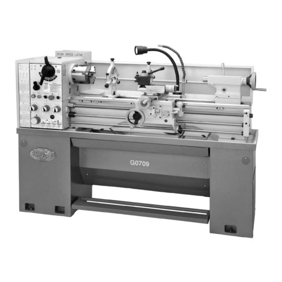
INTRODUCTION Manual Accuracy Contact Info your machine may not exactly match the manual Machine Description www.grizzly.com... - Page 5 Identification Figure 1.
-
Page 6: Machine Data Sheet
Machine Data Sheet Customer Service #: (570) 546-9663 · To Order Call: (800) 523-4777 · Fax #: (800) 438-5901 MODEL G0709 14 X 40 GUNSMITH'S GEARHEAD LATHE Weight... 1300 lbs. Length/Width/Height... 71-1/2 x 26-3/16 x 52 in. Foot Print (Length/Width)... 70-3/8 x 15-3/4 in. - Page 7 Bed Construction... Induction-Hardened Cast Iron Body Construction... Cast Iron Stand Construction... Cast Iron Paint... Epoxy Gear Box...Yes Country Of Origin ... China Warranty ... 1 Year Serial Number Location ... Machine ID Label on Front of Lathe Sound Rating ... 82 dB...
- Page 8 NSK precision tapered roller spindle bearings Flame hardened headstock gears Induction-hardened and precision ground cast iron bed Coolant system Adjustable halogen work light Foot brake with motor shut-off switch Full-length splash guard Pull-out chip tray 200-Series quick-change tool post Outboard spindle spider mount with 4 brass-tipped screws Cast iron cabinet stands Fully-enclosed quick-change gearbox Tailstock offset V-slide with wrench locking socket...
-
Page 9: Section 1: Safety
SECTION 1: SAFETY For Your Own Safety, Read Instruction Manual Before Operating this Machine The purpose of safety symbols is to attract your attention to possible hazardous conditions. This manual uses a series of symbols and signal words intended to convey the level of impor- tance of the safety messages. - Page 10 DISCONNECTING POWER SUPPLY. APPROVED OPERATION. DANGEROUS ENVIRONMENTS. ONLY USE AS INTENDED. USE RECOMMENDED ACCESSORIES. CHILDREN & BYSTANDERS. REMOVE ADJUSTING TOOLS. SECURING WORKPIECE. FEED DIRECTION. FORCING MACHINERY. GUARDS & COVERS. NEVER STAND ON MACHINE. STABLE MACHINE. AWKWARD POSITIONS. UNATTENDED OPERATION. MAINTAIN WITH CARE. CHECK DAMAGED PARTS.
-
Page 11: Additional Safety For Metal Lathes
Additional Safety for Metal Lathes CLEARING CHIPS. CHUCK KEY SAFETY. TOOL SELECTION. SPEED RATES. STOPPING SPINDLE BY HAND. LONG STOCK SAFETY. SAFE CLEARANCES. REMOVING/INSTALLING CHUCKS. SECURING WORKPIECE. CRASHES. CUTTING FLUID SAFETY. -
Page 12: Section 2: Power Supply
SECTION 2: POWER SUPPLY Availability Electrocution, equipment damage may occur if machine is not correctly grounded and connected to the power supply. Full-Load Current Rating Full-Load Current Rating at 220V ... 10 Amps Circuit Requirements for 220V Nominal Voltage ... 220V/240V Cycle ...60 Hz Phase ... -
Page 13: Grounding Instructions
Grounding Instructions GROUNDED 6-15 RECEPTACLE 6-15 PLUG Figure 2. Serious injury could occur if you connect the machine to power before completing the setup process. DO NOT connect to power until instructed later in this manual. Extension Cords Minimum Gauge Size ...14 AWG Maximum Length (Shorter is Better)...50 ft. -
Page 14: Section 3: Setup
SECTION 3: SETUP This machine presents serious injury hazards to untrained users. Read through this entire manu- al to become familiar with the controls and opera- tions before starting the machine! Wear safety glasses dur- ing the entire setup pro- cess! This machine and its com- ponents are very heavy. - Page 15 Inventory Mounted Inventory Components Loose Inventory Components Toolbox Inventory Components NOTICE Some hardware/fasteners on the inventory list may arrive pre-installed on the machine. Please check installation locations before assuming that any items from the inventory list are missing. Figure 3. Figure 4.
-
Page 16: Hardware Recognition Chart
Hardware Recognition Chart... -
Page 17: Site Considerations
Site Considerations Weight Load Machine Data Sheet Space Allocation See below for required space allocation. Children or untrained people may be seriously injured by this machine. Only install in an access restricted location. Note: Drawing Not to Scale. Physical Environment Electrical Installation Lighting Figure 6. - Page 18 Cleanup Before cleaning, gather the following: Basic steps for removing rust preventative: Steps 2–3 Gasoline or products with low flash points can explode or cause fire if used to clean machin- ery. Avoid cleaning with these products. Many cleaning solvents are toxic if concentrat- ed amounts are inhaled.
-
Page 19: Lifting & Moving
Additional Cleaning Tips H8257—Primrose Armor Plate with Moly-D Machine and Way Oil 1 Quart S. Balolia – President Figure 7. Lifting & Moving You must use power lifting equipment and assistance to lift and move this machine. Inspect all lifting equipment to make sure it is in working order and rated for the load before attempting to lift. -
Page 20: Bolting To Concrete Floors
Mounting Bolting to Concrete Floors Figure 9 Figure 9 NOTICE Anchor studs are stronger and more per- manent alternatives to lag shield anchors; however, they will stick out of the floor, which may cause a tripping hazard if you decide to move your machine. Using Machine Mounts Figure 10 NOTICE... -
Page 21: Adding Cutting Fluid
Adding Cutting Fluid Cutting fluid System Page 58 Power Connection Electrocution or fire may occur if machine is ungrounded, incor- rectly connected power, or connected to an undersized circuit. Use a qualified electri- cian to ensure a safe power connection. Test Run Troubleshooting To begin the test run:... - Page 22 NOTICE NEVER shift lathe gears when lathe is operating, and make sure both the half- nut lever and the feed selection lever are disengaged before you start the lathe! Otherwise the carriage may feed into the chuck or tailstock and cause severe damage.
- Page 23 Troubleshooting Page 59 Step OFF 16.
-
Page 24: Spindle Break-In
Spindle Break-In NOTICE Do not place this machine into service and subject it to normal work loads until it is completely broken-in and the gearbox oils have been changed! Otherwise, bearings can improperly seat, and gears can develop excessive backlash and result in vibration or noisy operation. -
Page 25: Section 4: Operation
OMMEND that you read books, trade maga- zines, or get formal training before begin- ning any projects. Regardless of the con- tent in this section, Grizzly Industrial will not be held liable for accidents caused by lack of training. Operation Overview... -
Page 26: Headstock Controls
Controls Headstock Controls Figure 13 Figure 13. Spindle Speed Range Lever Spindle Speed Lever Feed Direction Lever Power Light Power Button Cutting fluid ON/OFF Switch Feed Speed Dials Stop Button Jog Button Note: In order to use the jog button, the Spindle ON/OFF lever must be in the central or OFF posi- tion. -
Page 27: Apron Controls
Apron Controls Figure 14 Figure 14. Spindle ON/OFF Lever Feed Selection Lever Carriage Lock Half-Nut Lever Thread Dial Figure 15. Carriage Handwheel Cross Slide Handwheel Compound Slide Handwheel Compound Slide Scale... - Page 28 Tailstock Brake Figure 17 Figure 16 Figure 16. Quill Lock Lever Figure 17. Tailstock Lock Lever Drive Hub Tailstock Handwheel Micrometer Scale...
-
Page 29: Chuck & Faceplate Removal/Installation
Figure 20 Figure 20. PINCH HAZARD! Protect your hands and the precision ground bedways with plywood or a chuck cradle when removing the lathe chuck! The heavy weight of a falling chuck can cause serious injury. Figure 21. Note: These cam-locks may be very tight. A... - Page 30 Large chucks are very heavy. Always get assistance when removing or installing large chucks to prevent personal injury or damage to the chuck or lathe. Figure 22. To install the chuck or face plate: Chuck & Faceplate Installation...
-
Page 31: Camlock Stud Installation
When using this lathe, securely clamp your workpiece and remove the chuck wrench! Thrown objects from a lathe can cause serious injury or death to the operator and to bystanders. Camlock Stud Installation Figure 24 Cam Lock Positioning: Figure 24... -
Page 32: Three-Jaw Chuck
Steps 2 3 Always securely tighten jaws and remove all tools from the lathe before start- ing spindle! Thrown objects from a lathe can cause seri- ous injury or death to the operator and to bystand- ers. Figure 26 Figure... -
Page 33: Four-Jaw Chuck
Four-Jaw Chuck Reversing Jaw Positions & Clamping a Workpiece Figure 27 Figure 27. To use the 4-jaw chuck: Page 67 Page 33 Figure 28 Figure 28. Figure 28 Centers... - Page 34 Figure 29 Figure 29. Faceplate However, just as with the 4-Jaw chuck, not all workpieces can be safely held. Holding a workpiece off center or holding a Figure 30 Figure 30 Figure 30.
- Page 35 To use the faceplate: Figure 31. Use a minimum of three independent clamp- ing devices when using faceplate. Failure to provide adequate clamping may cause workpiece to eject during operation. Centers Tip: Hand-held tapered bore wipers make this task very time efficient, and offer consistently clean bores.
- Page 36 Carbide-Tipped Dead Center Live Center Figure 34 Figure 34. To install a center into the tailstock: Installing Center in Tailstock Figure 35 Figure 35. To install a center into the tailstock: Removing Center from Tailstock Installing Center in Spindle Removing Center from Spindle...
-
Page 37: Offsetting Tailstock
Tailstock Quill Lock Lever Figure 36 Figure 36. Tailstock Lock Lever Tailstock Handwheel Offsetting Tailstock To offset the tailstock: Figure 37 Figure Figure 37. Figure... -
Page 38: Aligning Tailstock
Aligning Tailstock To align the tailstock: Note: Keep in mind that the point will have to be refinished whenever it is removed and returned to the chuck. Figure 38. Figure 39. Step 4. Figure 38 Figure 40. Figure 40 Step 1 Figure 39 Figure 40... -
Page 39: Drilling With Tailstock
Figure 41 Figure 41. NOTICE DO NOT forget to lock the tailstock to the ways after each adjustment. Drilling with Tailstock... - Page 40 Tip: When drilling or when tapping operations need to be done deep into a part, the quill can also be stabilized by slightly applying the lever to add drag and preload to the quill. To install a tanged drill or chuck: Tip: For maximum locking of large diameter drill bits, push and seat the drill bit into the quill with a clockwise rotation as to load the tang...
-
Page 41: Steady Rest & Follow Rest
Cutting Fluid System Figure 43 Figure 43. NOTICE Running the pump without adequate cutting fluid in the reservoir may permanently dam- age it. This type of damage is not covered by the warranty. Cutting Fluid Page 58 To use the cutting fluid system: Steady Rest &... - Page 42 To install the rests: Figure 44. Figure 44 Figure 39 To load a tool holder: Tool Post Figure Figure 45.
-
Page 43: Determining Spindle Speed
Figure 46. To avoid creating an entanglement hazard, remove the spider screws when not in use, and always disconnect the lathe from power when installing, removing, or adjusting the spider screws. Ignoring this warning can lead to personal injury or machine damage. -
Page 44: Changing Spindle Speed
Changing Spindle Speed Figure 48 Never move either lever while the spindle is rotating, or gear clash and tooth fracture may occur. Figure 48. To change the spindle speed: Figure 48 Figure 48 Figure 48... -
Page 45: Manual Feed
Manual Feed Power Feed Figure 50 Figure 49 Figure 49. Carriage Handwheel Figure 50. Cross Slide Handwheel Compound Slide Handwheel Feed Settings Page 44... -
Page 46: Feed Settings
Failure to fully understand this may cause the carriage to crash into the chuck. Feed Settings All required change gears are pre-installed on this lathe, and no external gears are required. To set up for a power feed operation: Figure 52 Figure 51. -
Page 47: Thread Settings
Figure 52. FATX1 Figure 53. Figure 53. Thread Settings Figure 52 To set up for threading: Figure 54. Figure 54 FBSW6 Figure... - Page 48 Figure 55. FBSW6 Figure 56. Figure 56. Feed Direction Lever Figure 55 Figure 57 Figure 57. Feed Selection Lever Figure 58. Figure 57 Figure 57...
-
Page 49: Thread Dial
Half-Nut Lever Figure 59. DO NOT engage the half nut if the leadscrew will rotate over 200 RPM, or if the carriage lock is applied. Disregarding this warning may cause damage to the bearings or the leadscrew shear pin to break. Thread Dial Figure 60 Thread Chart... - Page 50 Figure 60 TPI Divisible by 8: Figure 62 T.P.I. SCALE Figure 62. TPI Divisible by 4 & Not by 8: Figure 63 T.P.I. SCALE 1–4 Figure 63. Important: Once a number has been selected, continue using that number or its odd/even counterpart.
-
Page 51: Section 5: Accessories
SECTION 5: ACCESSORIES H6879—Lathe Operation & Maintenance Book Figure 66. G0688—Tool Post Grinder Figure 67. H6095—Digital Readout (DRO) Figure 68. T10118—Tailstock Digital Readout Figure 69. - Page 52 H9240—Water Soluble Machining Oil Figure 70. H5786—MT#3 x 4" Bull Nose Rolling Center H5902—MT#3 x 2" Bull Nose Rolling Center Figure 71. H5786—MT#3 Long Nose Precision Center Figure 72. G1070—MT3 Live Center Set Figure 73. T20501—Face Shield Crown Protector 4" T20502—Face Shield Crown Protector 7"...
- Page 53 Quick Change Tool Holders G5701—Boring Bar Holder ⁄ " G5704—Parting Tool Holder ⁄ G5705—Knurling Tool Holder G5703—Morse Taper Holder MT#3 G5700—Turning/Boring Holder G5699—Turning Holders ⁄ "~ ⁄ Figure 75. G5640—5-Pc. Indexable Carbide Tool Set G6706—Replacement TiN Coated Carbide Indexable Insert Figure 76.
- Page 54 ⁄ " ⁄ H4462 ⁄ " ⁄ H4463 ⁄ " ⁄ Figure 80. H2987—½" Bent Lathe Dog OVERALL H2988—1" Bent Lathe Dog LENGTH H2989—1½" Bent Lathe Dog " ⁄ " H2990—2" Bent Lathe Dog " ⁄ " H2991—3" Bent Lathe Dog "...
-
Page 55: Section 6: Maintenance
SECTION 6: MAINTENANCE Always disconnect power from the machine before performing maintenance. Ignoring this warning may result in serious personal injury. Schedule Every 6–8 Hours of Running Time: Page 54 Page 56 Each Week: Each Month: Every Six Months: Page 57 Unpainted Cast Iron Page 58 Page 70... -
Page 56: Ball Oiler Lubrication
Ball Oiler Lubrication Figure 84. Figure 82. Figure 85. Figure 86. Figure 83. - Page 57 Figure 87. Figure 88.
-
Page 58: Oil Reservoirs
Oil Reservoirs Checking & Adding Oil Figures 89 91 To add oil to the reservoirs: Figure 90. Figure 91. Figure 89. -
Page 59: Changing Oil
Changing Oil Tools Needed To change the oil in the reservoirs: V-Belt Tension Tools Needed To check the V-belt tension: Figure 93. Figure 92. Figure 93... -
Page 60: Cutting Fluid System
Cutting Fluid System BIOLOGICAL AND POISON HAZARD! Use the correct personal pro- tection equipment when handling cutting fluid and by follow federal, state, and fluid manufacturer requirements to properly dispose of cutting fluid. Tip: For speedy chip removal from the tank, a metal catch basket with handles can be made to lift out the metal chip buildup in the first chamber. -
Page 61: Section 7: Service
SECTION 7: SERVICE Troubleshooting Motor & Gearbox Wiring Page 74 Wiring Page 74 Page 41 Page 70... - Page 62 Operation and Work Results Page 61 Page 41 Page 61 Page 63 Page 61 Page 63 Page 61 Page 36 Page 61...
-
Page 63: Gib Adjustments
Gib Adjustments NOTICE When adjusting gibs, keep in mind that the goal of gib adjustment is to remove unnec- essary sloppiness from the slide without causing binding and excessive half nut wear. Tip: The compound and cross slide gibs have a gib lock screw that are shown in Figures 95 –96. -
Page 64: Compound Slide Gib
Compound Slide Gib Figure 96 Figure 96. Saddle Gib IMPORTANT: Do not loosen the more than a couple of turns or the components inside will come apart. Reinstalling these compo- nents is difficult and time consuming. Figure 97. Figure 98. Tools Needed Figure 97 To adjust the saddle slide gib:... -
Page 65: Backlash Adjustment
Backlash Adjustment Tools Needed To adjust the cross slide backlash: Figure 99 Figure 99. Figure 100. Figure 100 Step 2 Figure 100... -
Page 66: Half Nut Adjustment
Half Nut Adjustment Tools Needed To adjust the half nut: Figure 101 Figure 101. Steps 3–5 Leadscrew Endplay Adjustment Tools Needed To remove leadscrew end play: Figure 102 Figure 102 Figure... -
Page 67: Shear Pin Replacement
Shear Pin Replacement Figure 103 Figure 103. Tools Needed To replace the shear pin: Tip: For easy shear pin replacement in the future, use the center punch or a scribe and mark the end of the drive hub and the side of the leadscrew with a timing mark to indicate where true hole alignment is located. -
Page 68: Feed Clutch Adjustment
Feed Clutch Tools Needed Adjustment To adjust the feed rod clutch: Figure 104 Figure 104 Figure 104. -
Page 69: Bearing Preload
Tailstock Lock Tools Needed To adjust the tailstock lock lever: Figure 105 Figure 105. Bearing Preload Tools Needed To adjust the preload: Figure 106. Figure 106... - Page 70 Figure 107. NOTICE For the next step, DO NOT strike the wood- en block with excessive force. If you do, you can cause the tapered roller bearings to indent the mating races. If this dam- age occurs, one or more spindle bearings will have to be replaced, as this damage will generate vibration at higher spindle speeds.
- Page 71 Figure 110. Figure 110 To confirm that the bearings are correctly pre- loaded: Step...
-
Page 72: V-Belt Replacement
V-Belt Replacement Tools Needed To replace the V-belts on the lathe: Figure 111 Figure 111. Figure 112. Gap Insert Removal Tools Needed To remove the gap: Figure 112 Figure 113. & Installation Figure 113 Figure... - Page 73 To reinstall the gap: Figure...
-
Page 74: Brake Shoes
Brake Shoes Tools Needed To check/replace the brake linings: Figure 114. Figure 115 Figure 115. 2–5 Maintenance Step 7 Figure 114 115. Steps 2–5 Figure 114 Steps Page 53 Step 7 Figure... -
Page 75: Machine Storage
Machine Storage To prepare your machine for short-term stor- age (up to a year): Step 3 To prepare your machine for long-term stor- age (a year or more):... -
Page 76: Section 8: Wiring
SECTION 8: WIRING Wiring Safety Instructions SHOCK HAZARD. MODIFICATIONS. WIRE CONNECTIONS. CIRCUIT REQUIREMENTS. The photos and diagrams included in this section are best viewed in color. You can view these pages in color at www.grizzly.com. WIRE/COMPONENT DAMAGE. MOTOR WIRING. CAPACITORS/INVERTERS. EXPERIENCING DIFFICULTIES. -
Page 77: Wiring Overview
Wiring Overview Page 77 PLUG and CORD (NOT INCLUDED) Page 77 WORK LAMP Page 78 MAIN MOTOR Page 76 ELECTRICAL Page 77 BRAKE SWITCH Page 77 SPINDLE ON/OFF SWITCH READ ELECTRICAL SAFETY ON PAGE 74! Page 77 PUMP MOTOR Page 77 CONTROL PANEL... -
Page 78: Electrical Box Wiring
Electrical Box Wiring Main Box To Page To Page To Page To Page To Page To Page READ ELECTRICAL SAFETY ON PAGE 74! -
Page 79: Switches And Pump Motor
Switches and Pump Motor Switches To Page To Page 76 To Page 76 To Page To Page To Page To Page READ ELECTRICAL SAFETY ON PAGE 74! - Page 80 Page READ ELECTRICAL SAFETY ON PAGE 74! MOTOR DIRECTION 220V If the lathe chuck rotates in the opposite direction of what the spindle ON/OFF lever indicates, disconnect the lathe from power. At the motor junction box, swap the positions of the wires marked U .
-
Page 81: Electrical Box Photo
Electrical Box Photo READ ELECTRICAL SAFETY ON PAGE 74! -
Page 82: Section 9: Parts
SECTION 9: PARTS Headstock Case and Shift... -
Page 83: Headstock Parts List
Headstock Parts List PART # DESCRIPTION P07090001 SHIFT LEVER PRP45M ROLL PIN 5 X 32 PCAP74M CAP SCREW M6-1 X 18 PSS14M SET SCREW M8-1.25 X 12 P07090006 SHAFT P07090007 GEAR 51T P07090008 SHIFT FORK P07090009 O-RING 13.8 X 2.4 P14 P07090010 HEADSTOCK CASTING 10-1... -
Page 84: Headstock Drive
Headstock Drive... - Page 85 Headstock Drive Parts List PART # DESCRIPTION P07090042 BRAKE SHOE ASSEMBLY P07090047 DRUM PULLEY PRP49M ROLL PIN 5 X 25 P07090049 ANCHOR PIN P07090050 ROCKER BAR P07090051 ROCKER PIN PR39M EXT RETAINING RING 8MM P07090053 BEARING RETAINER P07090054 GASKET P6005Z BALL BEARING 6005Z PCAP11M CAP SCREW M8-1.25 X 16...
-
Page 86: Headstock Spindle
Headstock Spindle... - Page 87 Headstock Spindle Parts List REF PART # DESCRIPTION P07090100 GEAR 74T P30212-P5 TAPERED ROLLER BEARING P30212-P5 PR43M EXT RETAINING RING 50MM PR44M EXT RETAINING RING 72MM P07090104 BEARING RETAINER P07090105 SPINDLE PK11M KEY 6 X 6 X 40 PK167M KEY 8 X 8 X 85 P07090108 CAM LOCK P07090109 GASKET P16004...
-
Page 88: Change Gears
PART # DESCRIPTION PN31M HEX NUT M12-1.5 PW06M FLAT WASHER 12MM P07090203 CHANGE GEAR 33T PK14M KEY 5 X 5 X 18 PLUBE001M TAP-IN BALL OILER 6MM P07090206 SPINDLE P07090207 HEX NUT M20 X 1.5 P07090208 THRUST WASHER P07090209 CHANGE GEAR 33T P07090210 CHANGE GEAR 72T P07090211... -
Page 89: Quick Change Gearbox Drive
Quick Change Gearbox Drive... - Page 90 Quick Change Gearbox Drive Parts List PART # DESCRIPTION P07090301 SHAFT P07090302 OIL SEAL P07090303 BUSHING PCAP06M CAP SCREW M6-1 X 25 P07090305 SHIFT FORK A P07090306 SHIFT FORK B P07090307 BUSHING HOUSING P07090308 SHIFT FORK C P07090309 SHIFT FORK D P07090310 GASKET P07090311...
-
Page 91: Quick Change Gearbox Shift
Quick Change Gearbox Shift... - Page 92 Quick Change Gearbox Shift Parts List PART # DESCRIPTION P07090342 GASKET P07090344 LEFT COVER P07090346 RIGHT COVER P07090347 GASKET PFH19M FLAT HD SCR M4-.7 X 10 PSS01M SET SCREW M6-1 X 10 P07090361 O-RING 23.7 X 2.5 P07090362 PLUG PCAP33M CAP SCREW M5-.8 X 12 P07090386 CASE COVER...
- Page 93 Apron...
-
Page 94: Apron Parts List
PART # DESCRIPTION P07090501 GEAR 60T PRP05M ROLL PIN 5 X 30 P07090503 GEAR 18T P07090504 PINION 11T PSS11M SET SCREW M6-1 X 16 P07090506 BUSHING PCAP26M CAP SCREW M6-1 X 12 PW03M FLAT WASHER 6MM P07090509 GEAR 18T P07090510 IDLER SHAFT PCAP33M CAP SCREW M5-.8 X 12... -
Page 95: Cross Slide
Cross Slide... - Page 96 Cross Slide Parts List PART # DESCRIPTION P07090601 T-NUT P07090602 PIVOT PIN PCAP01M CAP SCREW M6-1 X 16 P07090604 BUSHING PLUBE002M TAP-IN BALL OILER 8MM P07090606 CROSS SLIDE P07090607 GIB SCREW P07090608 PRP02M ROLL PIN 3 X 16 P07090610 CROSS-SLIDE LEADSCREW PSS12M SET SCREW M6-1 X 25 PSS16M...
-
Page 97: Compound Slide
PART # DESCRIPTION PLUBE001M TAP-IN BALL OILER 6MM PSS12M SET SCREW M6-1 X 25 P07090715 INNER HUB PSTB003M STEEL BALL 6MM P07090723 COMPRESSION SPRING P07090749 COMPOUND SLIDE PSS09M SET SCREW M8-1.25 X 20 PK134M KEY 4 X 4 X 14 P07090755 COMPOUND LEADSCREW P07090756... - Page 98 PART # DESCRIPTION P07090801 PINNED KNOB PRP64M ROLL PIN 3 X 18 P07090803 JACK SCREW P07090804 FINGER SLIDE PSS02M SET SCREW M6-1 X 6 PN01M HEX NUT M6-1 P07090807 SLOTTED SCREW M6-1 X 30 PSS58M SET SCREW M6-1 X 18 P07090809 LOWER STEADY REST CASTING P07090810...
- Page 99 Tailstock...
-
Page 100: Tailstock Parts List
Tailstock Parts List PART # DESCRIPTION P07090901 HANDLE SHOULDER SCREW P07090902 DUAL THREAD CAP SCREW PSS57M SET SCREW M5-.8 X 20 PW02M FLAT WASHER 5MM P07090905 HANDWHEEL P07090906 INDEX RING P8102 THRUST BEARING 8102 PCAP15M CAP SCREW M5-.8 X 20 P07090909 FLANGE HUB P8102... - Page 101 REF PART # DESCRIPTION 1001 P07091001 COOLANT TANK 1002 P07091002 COOLANT PUMP 0.8HP 110V/220V 1-PH 1003 PN01M HEX NUT M6-1 1004 PLW03M LOCK WASHER 6MM 1005 PB18M HEX BOLT M6-1 X 15 1006 P07091006 COOLANT PIPE ASSEMBLY 1007 P07091007 MOUNTING BASE Pump REF PART # DESCRIPTION...
-
Page 102: Motor And Feed Rod
Motor and Feed Rod... - Page 103 CAP SCREW M10-1.5 X 40 1117 P07091117 TAPER PIN 8 X 60 1118 P07091118 HEX STUD M8-1.25 1119 P07091119 GEAR COVER 1120 P07091120 LATHE BED 1121 P07091121 KNURLED KNOB M10-1.5 1122 P07091122 RACK 1123 PN02M HEX NUT M10-1.5 1124 P07091124 STUD M10-1.5...
-
Page 104: Cabinet And Brake
Cabinet and Brake... - Page 105 Cabinet and Brake Parts List PART # DESCRIPTION 1352 PS19M PHLP HD SCR M5-.8 X 6 1353 P07091353 COVER 1354 P07091354 SPLASH GUARD 1355 PS68M PHLP HD SCR M6-1 X 10 1356 PCAP02M CAP SCREW M6-1 X 20 1357 PW03M FLAT WASHER 6MM 1358 P07091358...
-
Page 106: Main Electrical Breakdown
Main Electrical Breakdown REF PART # DESCRIPTION 1401 P07091401 TRANSFORMER WUXI JBK5-100VATH 1402 P07091402 CIRCUIT BREAKER 3A TIANSHUI, DZ451-63 1403 P07091403 CIRCUIT BREAKER 5A TIANSHUI, DZ451-63 1404 P07091404 OL RELAY TIANSHUI JRS4-09/25D 9-13A 1405 P07091405 OL RELAY TIANSHUI JRS4-09/25D 0.4-0.63A 1406 P07091406 CONTACTOR TIAN JZC3-40D 110V 1407 P07091407 CONTROL PANEL PLATE 1408 P07091408 COPPER GROUND BLOCK... - Page 107 PART # DESCRIPTION 1501 P07091501 TOOL BOX 1502 PWR911 OPEN END WRENCH 9/11MM 1503 PWR1214 COMBO WRENCH 12 X 14MM 1504 PWR1316 COMBO WRENCH 13 X 16MM 1505 PWR1719 COMBO WRENCH 17 X 19MM 1506 PWR2427 COMBO WRENCH 24 X 27MM 1507 PAW06M HEX WRENCH 6MM...
-
Page 108: Labels Breakdown
MUST maintain the original location and readability of the labels on the machine. If any label is removed or becomes unreadable, REPLACE that label before using the machine again. Contact Grizzly at (800) 523-4777 or www.grizzly.com to order new labels. REF PART #... -
Page 109: Warranty Card
The following information is given on a voluntary basis. It will be used for marketing purposes to help us develop better products and services. Of course, all information is strictly confidential. Note: We never use names more than 3 times. _____________________________________________________________________ _________________________________________________________________________________ _________________________________________________________________________________... -
Page 111: Warranty And Returns
WARRANTY AND RETURNS... - Page 112 ® Buy Direct and Save with Grizzly – Trusted, Proven and a Great Value! ~Since 1983~ Visit Our Website Today For Current Specials! ORDER 24 HOURS A DAY! 1-800-523-4777...
Need help?
Do you have a question about the G0709 and is the answer not in the manual?
Questions and answers