Table of Contents
Advertisement
Quick Links
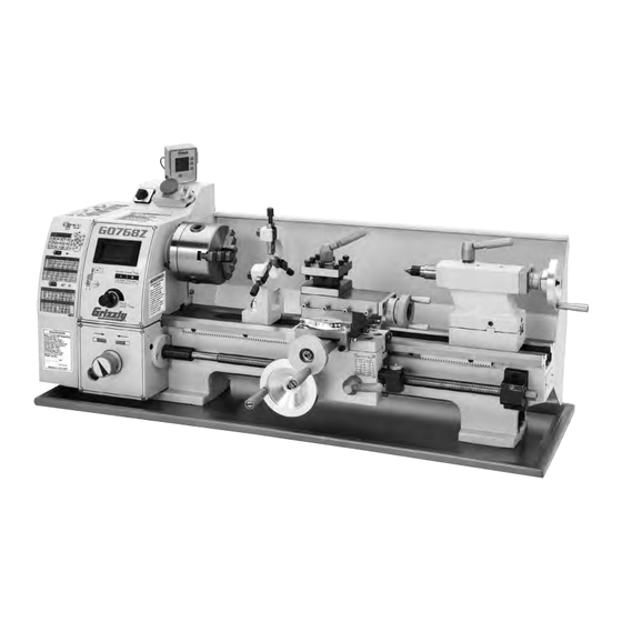
MODEL G0768Z
8" X 16" VARIABLE-
SPEED LATHE WITH DRO
MANUAL INSERT
Model G0768Z is an upgraded version of Model G0768 with an included X/Z-Axis DRO.
NOTE: The bed, saddle, and cross slide on this model have been specially machined to mount the DRO
scales. Thus, the DRO components included with this model cannot be easily retrofitted onto Model G0768.
: To reduce the risk of serious injury, you MUST read and understand this insert—and
the entire Model G0768 manual—BEFORE assembling, installing, or operating this machine!
If you have any further questions about this manual insert or the differences between the Model G0768 and
the Model G0768Z, contact our Technical Support at (570) 546-9663 or email techsupport@grizzly.com.
COPYRIGHT © JUNE, 2017 BY GRIZZLY INDUSTRIAL, INC.
WARNING: NO PORTION OF THIS MANUAL MAY BE REPRODUCED IN ANY SHAPE
OR FORM WITHOUT THE WRITTEN APPROVAL OF GRIZZLY INDUSTRIAL, INC.
(FOR MODELS MANUFACTURED SINCE 02/17) #KB18653 PRINTED IN CHINA
Advertisement
Table of Contents

Related Manuals for Grizzly G0768Z


Summary of Contents for Grizzly G0768Z
- Page 1 SPEED LATHE WITH DRO MANUAL INSERT Model G0768Z is an upgraded version of Model G0768 with an included X/Z-Axis DRO. NOTE: The bed, saddle, and cross slide on this model have been specially machined to mount the DRO scales. Thus, the DRO components included with this model cannot be easily retrofitted onto Model G0768.
- Page 2 P0768Z188 CAP SCREW M3-.5 X 6 P0768Z445 FLAT WASHER 4MM P0768Z189 Z-AXIS DRO SENSOR P0768Z704 VARIABLE SPEED LABEL P0768Z190 Z-AXIS SENSOR MOUNTING BRACKET P0768Z710 MACHINE ID LABEL P0768Z191 SPACER 3 X 7 X 6, PLASTIC Model G0768Z (Mfd. Since 02/17)
- Page 3 DRO Components Digital Readout Using the DRO A. DRO displays current position of X-axis and Model G0768Z features a magnetically mounted DRO (see Figure 1) for X-axis (cross slide) and Z-axis in hundredths of a millimeter or thou- Z-axis (carriage) travel.
- Page 5 For Machines Mfd. Since 6/17 and Owner's Manual Printed 6/17 For questions or help with this product contact Tech Support at (570) 546-9663 or techsupport@grizzly.com The following change was recently made to these machines since the owner's manual was printed: •...
- Page 6 (Replaces Page 90 in Manual) G0768 Wiring Diagram READ ELECTRICAL SAFETY G0768/G0769 Update (Mfd. Since 2/17) ON PAGE 42!
- Page 7 (Replaces Page 93 in Manual) G0769 Wiring Diagram READ ELECTRICAL SAFETY G0768/G0769 Update (Mfd. Since 2/17) ON PAGE 42!
- Page 9 (For models manufactured since 8/15) Model G0768 Model G0769 COPYRIGHT © AUGUST, 2014 BY GRIZZLY INDUSTRIAL, INC. REVISED JUNE, 2017 (HE) WARNING: NO PORTION OF THIS MANUAL MAY BE REPRODUCED IN ANY SHAPE OR FORM WITHOUT THE WRITTEN APPROVAL OF GRIZZLY INDUSTRIAL, INC.
- Page 10 This manual provides critical safety instructions on the proper setup, operation, maintenance, and service of this machine/tool. Save this document, refer to it often, and use it to instruct other operators. Failure to read, understand and follow the instructions in this manual may result in fire or serious personal injury—including amputation, electrocution, or death.
-
Page 11: Table Of Contents
Table of Contents INTRODUCTION ..........3 4-Jaw Chuck ..........35 Machine Description ........3 Faceplate ............. 36 Contact Info............ 3 Tailstock ............37 Manual Accuracy ........... 3 Tailstock Quill Specs ..........Identification (G0768)........4 Positioning Tailstock ..........Identification (G0769)........5 Using Quill .............. - Page 12 SECTION 5: MILL OPERATIONS ....60 SECTION 8: SERVICE ........78 Operation Overview ........60 Troubleshooting ........... 78 Removing Compound Rest ......61 Motor & Electrical ............Removing Compound Rest ........Lathe Operation ............Re-installing Compound Rest ........Mill Operation ............Headstock Movement ........
-
Page 13: Introduction
We post current lathe/mill selector switch also makes chang- manuals and manual updates for free on our web- site at www.grizzly.com. ing between lathe and milling modes easy. Alternatively, you can call our Technical Support Both machines can be mounted on a sturdy work- for help. -
Page 14: Identification (G0768)
Identification (G0768) Become familiar with the names and locations of the controls and features shown below to better understand the instructions in this manual. On/Off Switch w/ Emergency Stop Button Steady Rest 4-Way 3-Jaw Spindle Direction Tool Post Chuck Switch Compound Rest Handwheel Tailstock... -
Page 15: Identification (G0769)
Identification (G0769) Become familiar with the names and locations of the controls and features shown below to better understand the instructions in this manual. Fine Downfeed Handwheel Vertical Travel Handwheel Lathe/Mill Selector Spindle Switch Lock On/Off Switch w/ 3-Jaw Vertical Travel Emergency Stop Chuck Lock Levers... -
Page 16: Controls & Components
Controls & E. ON/OFF Switch w/Emergency Stop Button: When pressed, cuts power to motor and con- Components trol panel. To reset, press front tab, lift switch cover, and press green ON button. Cover must be unlatched for machine to run. Lathe/Mill Selector Switch (G0769 Only): Used to select between lathe mode (1), or To reduce your risk of... -
Page 17: Tailstock
Tailstock End Gears, Pulleys, V-Belts U. End Gears: The configuration of the end gears controls the leadscrew speed for power feeding, and inch and metric threading. V-Belts: Transfer power from motor to idler and spindle pulleys. The position of the top V-belt on idler and spindle pulleys controls spindle speed. -
Page 18: Milling Headstock (G0769 Only)
Milling Headstock (G0769 Only) Figure 8. Left side milling headstock controls. Figure 7. Right side milling headstock controls. AB. Vertical Handwheel: Raises and lowers headstock for Z-axis control over spindle X. Fine Downfeed Handwheel: Provides fine positioning during setups. control over vertical spindle travel to provide Z-axis control when milling. -
Page 19: G0768 Data Sheet
MACHINE DATA SHEET Customer Service #: (570) 546-9663 · To Order Call: (800) 523-4777 · Fax #: (800) 438-5901 MODEL G0768 8" X 16" VARIABLE‐SPEED LATHE Product Dimensions: Weight................................144 lbs. Width (side-to-side) x Depth (front-to-back) x Height................36 x 16 x 14 in. Footprint (Length x Width)....................... - Page 20 Headstock Info Spindle Bore............................0.787 in. Spindle Taper............................MT#3 Number of Spindle Speeds........................Variable Spindle Speeds..................... 50 – 1000, 100 – 2000 RPM Spindle Type........................Intrinsic Back Plate Spindle Bearings......................... Tapered Roller Spindle Length............................8-5/8 in. Spindle Length with 3-Jaw Chuck....................... 10-5/8 in. Spindle Length with 4-Jaw Chuck.......................
-
Page 21: G0769 Data Sheet
MACHINE DATA SHEET Customer Service #: (570) 546-9663 · To Order Call: (800) 523-4777 · Fax #: (800) 438-5901 MODEL G0769 8" X 16" LATHE WITH MILLING HEAD Product Dimensions: Weight................................234 lbs. Width (side-to-side) x Depth (front-to-back) x Height................36 x 20 x 34 in. Footprint (Length x Width)....................... - Page 22 Main Specifications: Lathe Info Swing Over Bed............................. 8-1/4 in. Distance Between Centers........................15-3/4 in. Swing Over Cross Slide......................... 4-5/8 in. Swing Over Saddle..........................6-7/8 in. Maximum Tool Bit Size..........................3/8 in. Compound Travel..........................2-1/8 in. Carriage Travel............................ 15-3/4 in. Cross Slide Travel............................3 in. Spindle Bore..........................
-
Page 23: Section 1: Safety
SECTION 1: SAFETY For Your Own Safety, Read Instruction Manual Before Operating This Machine The purpose of safety symbols is to attract your attention to possible hazardous conditions. This manual uses a series of symbols and signal words intended to convey the level of impor- tance of the safety messages. - Page 24 WEARING PROPER APPAREL. Do not wear FORCING MACHINERY. Do not force machine. clothing, apparel or jewelry that can become It will do the job safer and better at the rate for entangled in moving parts. Always tie back or which it was designed. cover long hair.
-
Page 25: Additional Safety For Metal Lathes
Additional Safety for Metal Lathes The primary risks of operating a Metal Lathe are as follows: You can be seriously injured or killed by getting entangled in, crushed between, or struck by rotating parts on a lathe. You can be struck with deadly force by unsecured tools or workpieces attached to rotating objects. To reduce your risk of serious injury when operating this machine, completely heed and understand the following: CLOTHING, JEWELRY &... -
Page 26: Additional Safety For Mills/Drills
Additional Safety for Mills/Drills The primary risks of operating a mill are as follows: You can be seriously injured or killed by getting clothing, jewelry, or long hair entangled with rotating cutter/spindle. You can be severely cut or have fingers amputated from contact with the rotating cutter. You can be blinded or struck by broken cutting tools, metal chips, workpieces, or adjustment tools thrown from the rotating spindle with great force. -
Page 27: Additional Lathe Chuck Safety
Additional Lathe Chuck Safety ENTANGLEMENT. Entanglement with a rotat- CHUCK CAPACITY. Avoid exceeding the capacity ing chuck can lead to death, amputation, broken of the chuck by clamping an oversized workpiece. bones, or other serious injury. Never attempt to If the workpiece is too large to safely clamp with slow or stop the lathe chuck by hand, and always the chuck, use a faceplate or a larger chuck if pos- roll up long sleeves, tie back long hair, and remove... -
Page 28: Section 2: Power Supply
SECTION 2: POWER SUPPLY Availability Before installing the machine, consider the avail- ability and proximity of the required power supply Serious injury could occur if you connect circuit. If an existing circuit does not meet the machine to power before completing setup requirements for this machine, a new circuit must process. -
Page 29: Grounding & Plug Requirements
Grounding & Plug Requirements Improper connection of the equipment-grounding wire can result in a risk of electric shock. The This machine MUST be grounded. In the event wire with green insulation (with or without yellow of certain malfunctions or breakdowns, grounding stripes) is the equipment-grounding wire. -
Page 30: Section 3: Setup
Unpack machine and inventory contents of you are completely satisfied with the machine and box/crate. have resolved any issues between Grizzly or the shipping agent. You MUST have the original pack- Clean machine and its components. aging to file a freight claim. It is also extremely helpful if you need to return your machine later. -
Page 31: Inventory
Inventory Fuse Set ............. 1 — 10A (G0768) ........... 1 — 15A (G0768) ........... 1 — 10A (G0769) ........... 2 The following is a list of items shipped with your — 15A (G0769) ........... 1 machine. Before beginning setup, lay these items W. -
Page 32: Cleanup
Cleanup Gasoline and petroleum products have low flash The unpainted surfaces of your machine are points and can explode coated with a heavy-duty rust preventative that or cause fire if used to prevents corrosion during shipment and storage. clean machinery. Avo i d This rust preventative works extremely well, but it u sing t h e s e p r o d u c t s will take a little time to clean. -
Page 33: Site Considerations
Site Considerations Weight Load Physical Environment Refer to the Machine Data Sheet for the weight The physical environment where the machine is of your machine. Make sure that the surface upon operated is important for safe operation and lon- which the machine is placed will bear the weight gevity of machine components. -
Page 34: Lifting & Placing
Lifting & Placing To balance load for lifting, move tailstock and carriage to extreme right end of bedway, then lock them in place. Note: Before trying to move carriage, make sure carriage lock is loose and half nut is disengaged. HEAVY LIFT! Straining or crushing injury Wrap lifting slings around bed and between... -
Page 35: Mounting
Mounting Follow these guidelines when mounting your machine to ensure safe and accurate cutting results: Number of Mounting Holes ......2 • Make sure stand or workbench can ade- Diameter of Mounting Hardware ....⁄ " quately support weight of machine and mate- rials, and that it will not move or vibrate dur- The chip pan and lathe base have holes that allow ing operation. -
Page 36: Leveling
See Figure 17 for an example of a high-precision level. Figure 17. Grizzly Model H2683 12" Master Machinist's Level. -26- Model G0768/G0769 (Mfd. Since 8/15) -
Page 37: Test Run
Test Run Set spindle direction switch to neutral ("0" position), and rotate spindle speed dial all the way counterclockwise. Once assembly is complete, test run the machine G0769 Only: Set lathe/mill selector switch to to ensure it is properly connected to power and "0"... - Page 38 Connect machine to power. The spindle 13. Rotate spindle speed dial all the way counter- speed RPM display will illuminate. clockwise. Press tab in on side of Emergency Stop but- 14. Set lathe/mill selector switch to "2" for mill ton and lift switch cover to reset it. mode.
-
Page 39: Spindle Break-In
Spindle Break-In Rotate spindle speed dial all the way coun- terclockwise, then press Emergency Stop button. The spindle break-in procedure distributes lubri- Set spindle direction switch to "R", then reset cation throughout the bearings to reduce the risk Emergency Stop button. of early bearing failure if there are any "dry"... -
Page 40: Recommended Adjustments
Recommended 14. Rotate spindle speed dial all the way coun- terclockwise, then press Emergency Stop Adjustments button. 15. Repeat Steps 7–10 from Lathe Spindle Break-In in a similar manner for mill. The following adjustments have been made at the factory. However, because of the many variables Congratulations! Mill spindle break-in is complete. -
Page 41: Section 4: Lathe Operations
Read books/magazines or get formal training before beginning any proj- ects. Regardless of the content in this sec- tion, Grizzly Industrial will not be held liable for accidents caused by lack of training. -31- Model G0768/G0769 (Mfd. Since 8/15) -
Page 42: Chuck & Faceplate Mounting
Chuck & Faceplate Chuck Installation Mounting To ensure accurate work, it is extremely important to make sure the spindle nose and chuck mating This lathe is equipped with an intrinsic backplate surfaces are clean. Even a small amount of lint or spindle nose. -
Page 43: Scroll Chuck Clamping
Scroll Chuck Insert (3) M8-1.25 X 35 set screws through mounting holes in spindle backplate, as Clamping shown in Figure 25. Make sure chuck seats firmly and evenly against backplate shoulder. This 3-jaw, scroll-type chuck has an internal scroll- gear that moves all jaws in unison when adjusted Spindle with the chuck key. -
Page 44: Changing Jaw Set
Changing Jaw Set To change jaw set: DISCONNECT MACHINE FROM POWER! The 3-jaw scroll chuck included with the lathe Use appropriate device to protect ways (refer features inside and outside hardened steel jaw to Installation & Removal Device subsec- sets (see Figure below), which move in unison to tion). -
Page 45: 4-Jaw Chuck
4-Jaw Chuck Tighten each jaw in small increments. After tightening first jaw, continue tightening remaining jaws in an opposing sequence, similar to sequential order shown below. Refer to the Chuck Installation subsection for instructions on installing the 4-jaw chuck. The 4-jaw chuck features independently adjust- able jaws for holding non-concentric or off-center workpieces. -
Page 46: Faceplate
Faceplate To mount a non-concentric workpiece to a faceplate: DISCONNECT MACHINE FROM POWER! Refer to the prior Chuck Installation subsection for instructions on installing the faceplate. Position appropriate device across bed ways to protect them from any potential damage The faceplate included with your lathe can be from workpiece contact during installation. -
Page 47: Tailstock
Tailstock Tailstock Quill Specs Graduated Dial on Handwheel Increments ..........0.001" One Full Revolution ........0.04" The tailstock is typically used to support long workpieces at the side opposite the spindle, using Increments on Quill Scale a live or dead center. It can also hold a tapered Inch ........ -
Page 48: Installing Tooling
Installing Tooling To install tooling in tailstock: The tailstock quill accepts MT#2 tapered arbors With tailstock locked in place, unlock quill, (see the Figures below for examples). then use handwheel to extend it approxi- mately 1". Tang Thoroughly clean and dry tapered mating Tang Screw Solid... -
Page 49: Aligning Tailstock To Spindle Centerline
Aligning Tailstock to Spindle Tools Needed Hex Wrench 4mm ..........1 Centerline This is an essential adjustment that should be ver- To offset tailstock: ified or performed each time the tailstock is used to turn concentric workpieces between centers Loosen tailstock lock to release clamping or immediately after offsetting the tailstock when pressure on top and bottom castings. - Page 50 Install center in tailstock. Use calipers to measure both ends of the workpiece. Attach a lathe dog to the test stock from Step 1, then mount it between centers, as shown — If test stock is thicker at tailstock end, below.
-
Page 51: Centers
Centers Mounting Dead Center in Spindle DISCONNECT MACHINE FROM POWER! Thoroughly clean and dry all mating surfaces Figure 43 shows the MT#2 and MT#3 dead cen- of spindle bore and center, making sure that ters included with the lathe. no lint or oil remains on these surfaces. Mount chuck or faceplate onto spindle, which- MT#2 Dead ever is correct for your operation. -
Page 52: Mounting Center In Tailstock
Mounting Center in Tailstock Removing Center from Tailstock The included #2 dead center or a live center (not To remove the center from the quill, hold onto it included) can be used in the tailstock. Mounting with a gloved hand or shop rag, then rotate the instructions are the same for both. -
Page 53: Steady Rest
Steady Rest Lubricate finger tips with an anti-seize lubri- cant during operation. Note: Mill or file the tips if they show wear. The steady rest supports long shafts and can Follow Rest be mounted anywhere along the length of the bedway. -
Page 54: Compound Rest
Compound Rest Four-Way Tool Post The four-way tool post is mounted on top of the The compound rest handwheel has an indirect- compound rest and allows a maximum of four read graduated scale. This means that the dis- tools to be loaded simultaneously. tance shown on the scale represents the actual distance the cutting tool moves. -
Page 55: Aligning Cutting Tool With Spindle Centerline
Aligning Cutting Tool with Spindle Tools Needed Tool Post T-Wrench ........... 1 Centerline Steel Shims ........As Needed For most operations, the cutting tool tip should be Cutting Tool ............1 aligned with the spindle centerline, as illustrated Tailstock Center ..........1 below. -
Page 56: Manual Feed
Manual Feed Spindle Speed The cutting tool can be manually fed into the Using the correct spindle speed is important for workpiece using the carriage, cross slide, and getting safe and satisfactory results, as well as compound rest handwheels shown below. maximizing tool life. -
Page 57: Spindle Speed
Setting Spindle Speed Range Configuration Example One of two spindle speed ranges is selected by Follow this example to gain a better understand- repositioning the top V-belt between the spindle ing of how to set the lathe spindle speed. and idler pulleys (see Figure 55). Select the A position for low (50-1000 RPM) or B position for To set spindle speed to 100 RPM: high (100–2000 RPM) speed ranges. - Page 58 Understanding Gear Move top V-belt to A position (see Figure 58) to select low speed range (50–1000 RPM). Charts High This subsection explains how to understand the feed and thread charts on the headstock. If you do V-Belt not understand lathe gear charts, or need a quick refresher, read this before configuring the end gears for power feeding or threading operations.
-
Page 59: Understanding Gear Charts
0.0037" 0.0068" 30 72 How to Read the Feed Chart Thread Charts—Display headstock end gear 33 80 positions used for cutting various metric or inch Figure 62 identifies the three available feed rates threads (see Figure 61). and the feed icon at the top of the feed rate chart. Metric Feed Rate Thread Chart... -
Page 60: How To Read The Feed Chart
How to Read the Thread Charts Each shaft has room to mount gears in two posi- tions—forward and rear (see Figure 64). Figure 66 identifies the charts to use when set- ting carriage feed movement for metric or inch threading. 0.0037"... - Page 61 Each shaft has room to mount gears in two posi- The lines shown between the numbers in Figure tions—forward and rear (see Figure 69). 70 indicate which gears should be in mesh. 9 10 11 12 57 7 Gear Mesh Forward Lines Rear...
-
Page 62: End Gears
Primary Threading Configuration Configuring End Gears This threading configuration is used for inch and Follow the example below to understand how metric threading. Mesh the A and C, and D and F to change the gears from the factory set power 9 10 11 12 13 14 16 18 gears, as shown in Figure 72. - Page 63 Loosen adjuster cap screw shown in Figure Remove keyed spacer from lower gear shaft 75, and pivot adjuster down to disengage (see Figure 77). gears. Keyed Spacer Adjuster Gear Hex Nut & Shafts E-Clips Shaft Hex Nut & Flat Washer Adjuster Cap Figure 77.
- Page 64 12. Remove 20T gear with keyed bushing from 16. Thread short end of 80T/60 gear shaft into 80T gear (see Figure 80). T-nut on adjuster until finger tight (see Figure 83). Keyed Bushing 80T Gear T-Nut 20T Gear Figure 80. 20T gear removed from 80T gear. Figure 83.
- Page 65 Power Feed 20. Re-install e-clips and hex nuts onto middle and top gear shafts. 21. Adjust lash between meshed gears so it The carriage has power feed (or automatic feed) is approximately 0.003", then tighten gear options for threading or non-threading operations. shafts and fasteners.
-
Page 66: Power Feed
B. Feed Rate Chart: Displays end gear settings D. Half Nut Lever: Engages/disengages half for selected feed rate (see Figure 88). nut for power feed operations. 0.0037" 0.0068" 30 72 33 80 Figure 90. Half nut lever. Figure 88. Feed chart. To avoid potential carriage/chuck crash, C. -
Page 67: Setting Power Feed Rate
Gather the required A–F change gears: 84T, Adjust lash between meshed gears so it is 30T, 20T and two 80T gears, based upon the approximately 0.003", then tighten the gear chart in Figure 91. shafts. Swing the adjuster up and mesh the 84T gear Remove end cover. -
Page 68: Threading
Apron Threading Controls To set lathe to thread 20 TPI right-hand threads: The half nut lever engages the carriage with the leadscrew, which moves the carriage and cutting Configure gears as instructed in End Gear tool along the length of the workpiece for thread- Configuration Example on Page 53. -
Page 69: Thread Dial
Thread Dial Chart Odd TPI: For threading odd numbered TPI, use any pair of opposite numbers on the thread dial The thread dial chart is located on the headstock, (see the example in Figure 99). as shown in Figure 96. Find the TPI (threads per inch) that you want to Table Thread Dial... -
Page 70: Section 5: Mill Operations
Read books/magazines or get formal training before beginning any proj- ects. Regardless of the content in this sec- tion, Grizzly Industrial will not be held liable for accidents caused by lack of training. -60- Model G0768/G0769 (Mfd. Since 8/15) -
Page 71: Removing Compound Rest
Removing Re-installing Compound Rest Align compound rest with swivel base mounting Compound Rest holes and nut (see Figure 103), then secure with cap screws previously removed. Note: While re-installing compound rest, use a The compound rest and tool post must be removed 3mm hex wrench to press swivel base up from before milling/drilling so the cross slide table can underneath and keep it from sliding back down... -
Page 72: Headstock Movement
Headstock Tilting Headstock Tools Needed Movement Wrench 16mm ........... 1 Wrench 14mm ........... 1 To tilt headstock: The milling headstock moves in the following ways: DISCONNECT MACHINE FROM POWER! • Travels up and down the column (Z-axis). Support headstock with one hand, then loos- •... -
Page 73: Carriage Handwheel (X-Axis)
Table Travel Carriage Handwheel (X-Axis) Graduated Dial Increments ........0.01" (0.25mm) One Full Revolution ......1" (25.4mm) The cross slide table travels in two directions, as illustrated in Figure 107: Use the carriage handwheel to move the carriage left or right along the bed. Adjust the position of •... -
Page 74: Using Spindle Downfeed Controls
Using Spindle Fine Downfeed Fine downfeed is typically used for milling applica- Downfeed Controls tions, because the spindle only moves up or down when the fine downfeed handwheel (see Figure 109) is rotated (there is no automatic spindle return to the top position, as with the coarse The Model G0769 features two different types of downfeed controls). -
Page 75: Installing/Removing Tooling
Installing/Removing Insert tooling into spindle until in contacts drawbar. Tooling Working from top, thread drawbar by hand into tooling until it is snug (see Figure 112). The Model G0769 includes a ⁄ " drill chuck with MT#2 arbor (see Figure 110). Figure 112. -
Page 76: Removing Tooling
Removing Tooling Tap top of drawbar with hammer to unseat taper (see Figure 114). Tools Needed Wrench 8mm ............. 1 Wrench 17mm............ 1 Wrench 25mm ........... 1 Brass Hammer ..........1 To remove tooling: DISCONNECT MACHINE FROM POWER! Remove drawbar cap. Loosen drawbar lock nut (see Figure 113) on previous page. -
Page 77: Spindle Speed
Spindle Speed Setting Spindle Speed Rotate spindle speed dial all the way coun- terclockwise to set spindle speed to lowest value. Using the correct spindle speed is important for safe and satisfactory results, as well as maximiz- Rotate high/low gearbox knob (see Figure ing tool life. -
Page 78: Section 6: Accessories
Installing unapproved accessories may cause machine to malfunction, resulting in serious personal injury or machine damage. To reduce this risk, only install accessories recommended for this machine by Grizzly. NOTICE Refer to our website or latest catalog for additional recommended accessories. - Page 79 " ⁄ " ⁄ " ⁄ " 2" ⁄ " ⁄ " ⁄ " Figure 122. G9788 4-Pc. Measuring Tool Set. Figure 124. HSS ground center-drill sets. www.grizzly.com 1-800-523-4777 order online at or call -69- Model G0768/G0769 (Mfd. Since 8/15)
- Page 80 ⁄ " Figure 128. MT#2 end mill holders. H3659 ⁄ " 1" ⁄ " H3660 ⁄ " 1" 3" Figure 126. 4-flute C-2 grade carbide end mills. www.grizzly.com 1-800-523-4777 order online at or call -70- Model G0768/G0769 (Mfd. Since 8/15)
-
Page 81: Section 7: Maintenance
This includes any surface that is vulner- able to rust if left unprotected. Use a quality ISO 68 way oil (see Page 68 for offerings from Grizzly) to prevent corrosion. -71-... -
Page 82: Lubrication
Lubrication Items Needed Clean Rag ........As Needed Mineral Spirits ........As Needed Stiff Brush ............1 The lathe has metal-to-metal sliding surfaces that Pump-Type Oil Can w/Plastic Cone Tip .... 1 require regular lubrication to maintain smooth movement and ensure long-lasting operation. Ball Oilers Lube Type ....... -
Page 83: Leadscrew & Carriage Rack
Leadscrew & Carriage Rack Feed Gearbox Lube Type ..Model T23964 or NLGI#2 Equivalent Lube Type .. Model SB1365 or ISO 68 Equivalent Frequency ....... Annually or As Needed Lube Amount ........As Needed Lubrication Frequency ......... Daily The gearbox can be quickly lubricated (as necessary or if noisy) by removing the set screw Before lubricating the leadscrew and carriage shown in Figure 109 and adding a shot or two of... -
Page 84: End Gears
End Gears Lubricating DISCONNECT MACHINE FROM POWER! Lube Type ..Model T23964 or NLGI#2 Equivalent Frequency ....Annually or When Changing Remove end gear cover and all end gears shown in Figure 133. The end gears, shown in Figure 133, should always have a thin coat of heavy grease to Clean end gears thoroughly with mineral spir- minimize corrosion, noise, and wear. -
Page 85: Column Ways (G0769)
Column Ways (G0769) Quill Rack Lube Type .. Model SB1365 or ISO 68 Equivalent Lube Type ..Model T23964 or NLGI#2 Equivalent Lube Amount ........Thin Coat Lube Amount ........Thin Coat Lubrication Frequency ......... Daily Lubrication Frequency ..90 hrs. of Operation Regular lubrication will ensure your milling head- Move quill all the way down to gain full access to stock performs at its highest potential. -
Page 86: Z-Axis Leadscrew (G0769)
Z-Axis Leadscrew (G0769) Headstock Gears (G0769) Lube Type ..Model T23964 or NLGI#2 Equivalent Lube Type ..Model T23964 or NLGI#2 Equivalent Lube Amount ........Thin Coat Lube Amount ........Thin Coat Lubrication Frequency ..120 hrs. of Operation Lubrication Frequency ..90 hrs. of Operation To lubricate headstock gears: Lower headstock approximately ⁄... -
Page 87: Machine Storage
Machine Storage Bringing Machine Out of Storage Remove moisture-absorbing desiccant packs from electrical box. To prevent the development of rust and corrosion, Repeat Test Run and Spindle Break-In pro- the lathe must be properly prepared if it will be cedures, beginning on Page 27. stored for a long period of time. -
Page 88: Section 8: Service
SECTION 8: SERVICE Review the troubleshooting and procedures in this section if a problem develops with your machine. If you need replacement parts or additional help with a procedure, call our Technical Support. Note: Please gather the serial number and manufacture date of your machine before calling. Troubleshooting Motor &... -
Page 89: Lathe Operation
Lathe Operation Symptom Possible Cause Possible Solution Bad surface finish. 1. Wrong spindle speed or feed rate. 1. Adjust for appropriate spindle speed and feed rate. 2. Dull tooling or poor tool selection. 2. Sharpen tooling or select a better tool for the intended operation. -
Page 90: Mill Operation
Mill Operation Symptom Possible Cause Possible Solution Tool slips in spindle. 1. Tool is not fully drawn up into spindle taper. 1. Tighten drawbar (Do not overtighten). 2. Debris on tool or in spindle taper. 2. Clean collet and spindle taper. 3. -
Page 91: Tensioning & Replacing V-Belts
Tensioning & Turn tensioner screw (see Figure 141) clock- wise to tension V-belts or counterclockwise to Replacing V-Belts loosen V-belts. —If replacing V-belts, loosen idler pulley and carefully roll upper and lower V-belts off of V-belts stretch and wear with use, so it is impor- pulleys, then re-install new V-belts in same tant to routinely monitor belt tension. -
Page 92: Adjusting Backlash
Adjusting Backlash Adjusting Leadscrew End Play Backlash is the amount of free play felt while changing rotation directions with the handwheel. After a long period of time, you may find that the This can be adjusted on the cross slide leadscrew. leadscrew develops excessive end play. -
Page 93: Adjusting Gibs
Adjusting Gibs Adjusting Cross Slide and Compound Slide Gibs DISCONNECT MACHINE FROM POWER! The goal of adjusting the gib screws is to remove Loosen hex nuts on side of cross slide or sloppiness or "play" from the ways without over- compound slide (see Figures 145–146). -
Page 94: Adjusting Z-Axis Way Gib
Adjusting Half Nut Adjusting Z-Axis Way Gib Loosen one gib adjustment screw (see Figure 147) and tighten the opposing screw the same amount to move the gib, while at the same time The rigidity of the half nut engagement is adjusted using the handwheel to move the headstock until by tightening or loosening the half nut gib screws. -
Page 95: Replacing Leadscrew Shear Pin
Replacing Replacing Fuse Leadscrew Shear Pin This machine features on-board fuses designed to protect sensitive electrical parts from thermal The longitudinal leadscrew is secured to the feed damage in the event of an overload. If the spindle rate gearing in the headstock with the use of a does not start, replace the fuses. -
Page 96: Replacing Brushes
Replacing Brushes Remove motor mount cap screws (see Figure 151). Rotate motor to access top motor brush This machine is equipped with one (G0768) or two shown in Figure 152. (G0769) universal motors that use carbon brushes to transmit electrical current inside the motor. These brushes are considered to be regular "wear items"... -
Page 97: Replacing Mill Motor Brushes (G0769)
Replacing Mill Motor Brushes (G0769) Unscrew front brush cap and carefully remove brush from motor (see Figure 155). DISCONNECT MACHINE FROM POWER! Remove drawbar cap, then remove motor cover by removing cap screws (see Figure 154). Cap Screw Brush (1 of 4) Drawbar Brush Cap Figure 155. -
Page 98: Section 9: Wiring
Technical Support at (570) 546-9663. The photos and diagrams included in this section are best viewed in color. You can view these pages in color at www.grizzly.com. -88- Model G0768/G0769 (Mfd. Since 8/15) -
Page 99: G0768 Wiring Overview
G0768 Wiring Overview Direction Switch Emergency Stop Fuses Plug JD-014 RPM Sensor REV 091111 (Inside) Circuit Board DC Motor Speed Control JYMC-220B-II Potentiometer JD-013 REV C 120823 Circuit Board Motor (Inside) 110V 10A Single-Phase ⁄ HP 5250 RPM -89- Model G0768/G0769 (Mfd. Since 8/15) -
Page 100: G0768 Wiring
G0768 Wiring -90- Model G0768/G0769 (Mfd. Since 8/15) -
Page 101: G0768 Wiring Photos
G0768 Wiring Photos Figure 158. RPM sensor. Figure 156. Front panel. Figure 159. Back panel. Figure 157. Top panel. -91- Model G0768/G0769 (Mfd. Since 8/15) -
Page 102: G0769 Wiring Overview
G0769 Wiring Overview Mill Motor (Inside) 110V 10A Single-Phase ⁄ HP 4800 RPM Lathe/Mill Selector Switch Emergency Stop Fuses and Plug Direction RPM Sensor Switch (Inside) Speed Control Potentiometer Circuit Board Lathe Motor (Inside) 110V 10A Filter Single-Phase Circuit Board ⁄... -
Page 103: G0769 Wiring
G0769 Wiring -93- Model G0768/G0769 (Mfd. Since 8/15) -
Page 104: G0769 Wiring Photos
G0769 Wiring Photos Figure 160. Front panel. Figure 163. RPM sensor. Figure 161. Top panel components. Figure 164. Back panel. Figure 162. Mill/drill motor. -94- Model G0768/G0769 (Mfd. Since 8/15) -
Page 105: Section 10: Parts
SECTION 10: PARTS Headstock REF PART # DESCRIPTION REF PART # DESCRIPTION P0768001 CAP SCREW M5-.8 X 25 P0768026 FLAT WASHER 8MM P0768002 FLAT WASHER 5MM P0768027 HEX NUT M8-1.25 P0768003 MOTOR 600W 110VDC (G0768) P0768030 END GEAR COVER (G0768) P0769003 MOTOR 600W 110VDC (G0769) P0769030 END GEAR COVER (G0769) P0768004 MOTOR PULLEY... -
Page 106: Carriage Components & Accessories
Carriage Components & Accessories 112V2 179-1 G0769 Only -96- Model G0768/G0769 (Mfd. Since 8/15) - Page 107 Please Note: We do our best to stock replacement parts whenever possible, but we cannot guarantee that all parts shown here are available for purchase. Call (800) 523-4777 or visit our online parts store at www.grizzly.com to check for availability.
- Page 108 Steady & Follow Rest 174-5 174-6 174-4 174-3 175-4 175-5 174-2 175-3 175-6 174-1 175-2 175-1 174-7 174-8 174-9 174-10 REF PART # DESCRIPTION PART # DESCRIPTION P0768174 STEADY REST ASSEMBLY 174-9 P0768174-9 BASE CLAMP 174-1 P0768174-1 HEX NUT M8-1.25 174-10 P0768174-10 HEX BOLT M8-1.25 X 45 174-2 P0768174-2...
-
Page 109: Apron
Apron 238V2 REF PART # DESCRIPTION PART # DESCRIPTION P0768202 LOCK NUT M8-1.25 P0768220 SUPPORT BAR P0768203 CARRIAGE HANDWHEEL (G0768) P0768221 SET SCREW M6-1 X 8 P0769203 CARRIAGE HANDWHEEL (G0769) P0768222 COMPRESSION SPRING 0.6 X 3.5 X 12 P0768204 CURVED PLATE P0768223 STEEL BALL 4.5MM P0768205... -
Page 110: Gearbox
Gearbox 308 309 327 328 REF PART # DESCRIPTION REF PART # DESCRIPTION P0768301 DIRECTION INDICATOR PLATE P0768322 SHAFT (G0768) P0768302 SET SCREW M6-1 X 10 G0769322 SHAFT (G0769) P0768303 COMPRESSION SPRING 0.8 X 4 X 16 P0768323 SET SCREW M4-.7 X 8 P0768304 STEEL BALL 5MM P0768324... -
Page 111: Bed & End Gears
Bed & End Gears REF PART # DESCRIPTION REF PART # DESCRIPTION P0768401 EXT RETAINING RING 8MM P0768422 THRUST BEARING 51100 P0768402 GEAR 84T P0768423 LEADSCREW BRACKET (RH) P0768403 GEAR 30T P0768424 COUPLING NUT M8-1.25 X 20 P0768404 BUSHING P0768425 SET SCREW M4-.7 X 12 P0768405 THREADED SHAFT... -
Page 112: Tailstock
Tailstock REF PART # DESCRIPTION REF PART # DESCRIPTION P0768501 SHOULDER SCREW M5-.8 X 6 P0768519 QUILL LOCK HUB P0768502 HANDWHEEL HANDLE P0768520 QUILL LOCK PLUNGER P0768503 COUPLING NUT M6-1 P0768521 QUILL P0768504 QUILL HANDWHEEL (G0768) P0768522 TAILSTOCK CASTING P0769504 QUILL HANDWHEEL (G0769) P0768523 SET SCREW M8-1.25 X 25 P0768505 CURVED PLATE P0768524 LOCK BLOCK... -
Page 113: G0769 Mill Column
G0769 Mill Column REF PART # DESCRIPTION REF PART # DESCRIPTION P0769601 MILL HEADSTOCK MOUNT P0769611 SHOULDER SCREW M5-.8 X 55, 10 P0769602 Z-AXIS GIB P0769612 KEY 4 X 4 X 20 P0769603 GIB ADJUSTMENT SCREW P0769613 HANDWHEEL HANDLE P0769604 COLUMN P0769614 Z-AXIS LEADSCREW NUT... -
Page 114: G0769 Mill Headstock
G0769 Mill Headstock -104- Model G0768/G0769 (Mfd. Since 8/15) - Page 115 G0769 Mill Headstock REF PART # DESCRIPTION REF PART # DESCRIPTION P0769701 ALIGNMENT WASHER P0769744 FINE DOWNFEED GRADUATED DIAL P0769702 BUSHING P0769745 WORM SHAFT P0769703 COMPRESSION SPRING 2.5 X 28 X 100 P0769746 SPINDLE MT#2 P0769704 EXT RETAINING RING 45MM P0769747 QUILL SEAL, RUBBER (LOWER) P0769705 BALL BEARING 6909ZZ P0769748 TAPERED ROLLER BEARING 32005...
-
Page 116: G0768 Labels & Cosmetics
Safety labels help reduce the risk of serious injury caused by machine hazards. If any label comes off or becomes unreadable, the owner of this machine MUST replace it in the original location before resuming operations. For replacements, contact (800) 523-4777 or www.grizzly.com. -106-... -
Page 117: G0769 Labels & Cosmetics
Safety labels help reduce the risk of serious injury caused by machine hazards. If any label comes off or becomes unreadable, the owner of this machine MUST replace it in the original location before resuming operations. For replacements, contact (800) 523-4777 or www.grizzly.com. -107-... -
Page 118: G0768 Electrical Component Diagram
G0768 Electrical Component Diagram Top Panel Front Panel Inside Electrical Compartment Rear Panel REF PART # DESCRIPTION REF PART # DESCRIPTION P0768902 E-STOP KEDU JD17B 120V P0768908 SPEED CONTROL CIRCUIT BOARD P0768903 ROTARY SWITCH KEDU ZHA EN61058 P0768909 FILTER CIRCUIT BOARD P0768904 DRO CIRCUIT BOARD P0768910... -
Page 119: G0769 Electrical Component Diagram
G0769 Electrical Component Diagram Top Panel Front Panel Inside Electrical Compartment Rear Panel REF PART # DESCRIPTION REF PART # DESCRIPTION P0769901 ROTARY SWITCH LW8-10/6 P0769907 FUSE HOLDER MF528 15A 250V P0769902 E-STOP KEDU JD17B 120V P0769908 SPEED CONTROL CIRCUIT BOARD P0769903 ROTARY SWITCH KEDU ZHA EN61058 P0769909... -
Page 120: Section 11: Appendix
SECTION 11: APPENDIX Threading & Feeding Thread Dial Chart Chart INDICATOR TABLE SCALE 0.0037" 0.0068" 30 72 1, 4, 7 All Others 33 80 0.40 0.50 0.60 0.70 0.80 1.00 33 53 30 60 40 40 1.25 1.50 1.75 2.00 2.50 3.00 7163 33 3060 40 n/1"... - Page 121 Would you recommend Grizzly Industrial to a friend? _____ Yes _____No Would you allow us to use your name as a reference for Grizzly customers in your area? Note: We never use names more than 3 times. _____ Yes _____No 10.
- Page 122 FOLD ALONG DOTTED LINE Place Stamp Here GRIZZLY INDUSTRIAL, INC. P.O. BOX 2069 BELLINGHAM, WA 98227-2069 FOLD ALONG DOTTED LINE Send a Grizzly Catalog to a friend: Name_______________________________ Street_______________________________ City______________State______Zip______ TAPE ALONG EDGES--PLEASE DO NOT STAPLE...
-
Page 123: Warranty & Returns
WARRANTY & RETURNS Grizzly Industrial, Inc. warrants every product it sells for a period of 1 year to the original purchaser from the date of purchase. This warranty does not apply to defects due directly or indirectly to misuse, abuse, negligence, accidents, repairs or alterations or lack of maintenance.
Need help?
Do you have a question about the G0768Z and is the answer not in the manual?
Questions and answers