Table of Contents
Advertisement
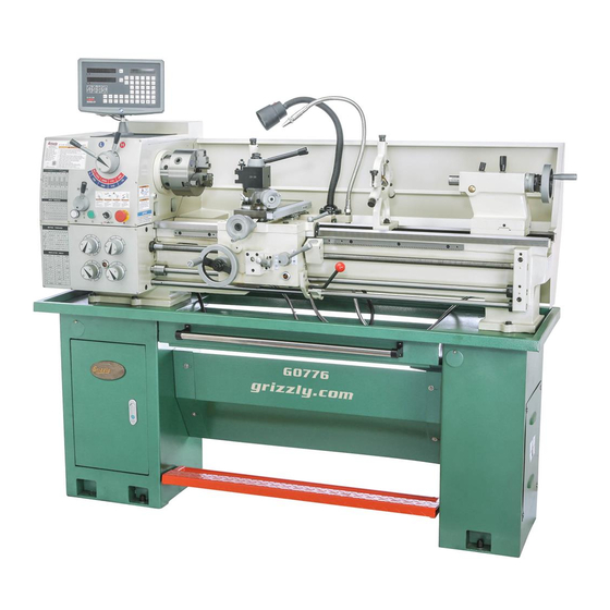
MODEL G0776
13" x 40" GUNSMITH LATHE w/DRO
OWNER'S MANUAL
(For models manufactured since 7/14)
COPYRIGHT © MARCH, 2015 BY GRIZZLY INDUSTRIAL, INC. REVISED NOVEMBER, 2017 (HE)
WARNING: NO PORTION OF THIS MANUAL MAY BE REPRODUCED IN ANY SHAPE
OR FORM WITHOUT THE WRITTEN APPROVAL OF GRIZZLY INDUSTRIAL, INC.
#WK17052 PRINTED IN CHINA
V1.11.17
Advertisement
Table of Contents

Related Manuals for Grizzly G0776


Summary of Contents for Grizzly G0776
- Page 1 OWNER'S MANUAL (For models manufactured since 7/14) COPYRIGHT © MARCH, 2015 BY GRIZZLY INDUSTRIAL, INC. REVISED NOVEMBER, 2017 (HE) WARNING: NO PORTION OF THIS MANUAL MAY BE REPRODUCED IN ANY SHAPE OR FORM WITHOUT THE WRITTEN APPROVAL OF GRIZZLY INDUSTRIAL, INC.
- Page 2 This manual provides critical safety instructions on the proper setup, operation, maintenance, and service of this machine/tool. Save this document, refer to it often, and use it to instruct other operators. Failure to read, understand and follow the instructions in this manual may result in fire or serious personal injury—including amputation, electrocution, or death.
-
Page 3: Table Of Contents
Table of Contents INTRODUCTION ..........3 Steady Rest ..........43 Machine Description ........3 Follow Rest ..........44 Contact Info............ 3 Carriage & Slide Locks ........ 45 Manual Accuracy ........... 3 Compound Rest ........... 45 Identification ........... 4 Tool Post ............46 Controls &... - Page 4 SECTION 9: PARTS ........97 Stand/Brake/Coolant Pump ......97 Headstock ............ 99 Headstock Controls........101 Gearbox ............. 103 Gearbox Controls ........105 Change Gears..........107 Apron ............108 Cross Slide..........110 Compound Rest & Tool Post ..... 112 Tailstock ............. 114 Lathe Bed &...
-
Page 5: Introduction
Manual Accuracy Machine Description We are proud to provide a high-quality owner’s The Model G0776 13" x 40" Gunsmith Lathe fea- manual with your new machine! tures a 2-axis digital readout, 8-speed gearhead, powerful 2 HP motor, and a D1-4 spindle with We made every effort to be exact with the instruc- a generous 1.57"... -
Page 6: Identification
DO NOT machine. Do not operate this machine until connect power until instructed to do so later you have understood this entire manual and in this manual. received proper training. Model G0776 (Mfd. Since 7/14) -
Page 7: Controls & Components
To reduce your risk of E. Quick-Change Gearbox Levers and Dial: serious injury, read this Controls leadscrew and feed rod speed for entire manual BEFORE threading and feeding operations. using machine. Model G0776 (Mfd. Since 7/14) - Page 8 Quill Handwheel: Moves quill toward or away from spindle. U. Offset Scale: Indicates relative distance of tailstock offset from spindle centerline. V. Offset Locking Set Screw: Locks tailstock in position left or right of spindle centerline. Model G0776 (Mfd. Since 7/14)
- Page 9 Twist clockwise to reset. End Gears Gears Figure 7. End gear components. Configuring the end gears (shown in Figure 7) controls the speed of the leadscrew for threading or the feed rod for power feed operations. Model G0776 (Mfd. Since 7/14)
-
Page 10: Machine Data Sheet
MACHINE DATA SHEET Customer Service #: (570) 546-9663 · To Order Call: (800) 523-4777 · Fax #: (800) 438-5901 MODEL G0776 13" X 40" GUNSMITHING LATHE WITH DRO Product Dimensions: Weight................................1280 lbs. Width (side-to-side) x Depth (front-to-back) x Height..............74-1/2 x 31 x 58 in. - Page 11 The information contained herein is deemed accurate as of 11/16/2017 and represents our most recent product specifications. Model G0776 PAGE 2 OF 3 Due to our ongoing improvement efforts, this information may not accurately describe items previously purchased. Model G0776 (Mfd. Since 7/14)
- Page 12 Fluid Capacities Headstock Capacity..........................2.3 qt. Headstock Fluid Type..............ISO 32 (eg. Grizzly T23963, Mobil DTE Light) Gearbox Capacity........................... 0.68 qt. Gearbox Fluid Type............. ISO 68 (SB1365, Grizzly T23962, Mobil Vactra 2) Apron Capacity............................0.23 qt. Apron Fluid Type................ISO 68 (eg. Grizzly T23962, Mobil Vactra 2) Coolant Capacity............................
-
Page 13: Section 1: Safety
Everyday ery. Never operate under the influence of drugs or eyeglasses are NOT approved safety glasses. alcohol, when tired, or when distracted. -11- Model G0776 (Mfd. Since 7/14) - Page 14 EXPERIENCING DIFFICULTIES. If at any time debris. Make sure they are properly installed, you experience difficulties performing the intend- undamaged, and working correctly BEFORE ed operation, stop using the machine! Contact our operating machine. Technical Support at (570) 546-9663. -12- Model G0776 (Mfd. Since 7/14)
-
Page 15: Additional Safety For Metal Lathes
CLEARING CHIPS. Metal chips can be razor sharp. Avoid clearing them by hand or with a rag. MEASURING WORKPIECE. To reduce risk of Use a brush or vacuum instead. entanglement, never measure rotating workpieces. -13- Model G0776 (Mfd. Since 7/14) -
Page 16: Additional Chuck Safety
Always disconnect the lathe from power additional training from an experienced chuck user before performing these procedures. before using a chuck. -14- Model G0776 (Mfd. Since 7/14) -
Page 17: Glossary Of Terms
The following is a list of common definitions, terms and phrases used throughout this manual as they relate to this lathe and metalworking in general. Become familiar with these terms for assembling, adjusting or operating this machine. Your safety is VERY important to us at Grizzly! Arbor: A machine shaft that supports a cutting Gib: A tapered wedge located along a sliding tool. -
Page 18: Section 2: Power Supply
To reduce the risk of these hazards, avoid over- loading the machine during operation and make sure it is connected to a power supply circuit that meets the specified circuit requirements. -16- Model G0776 (Mfd. Since 7/14) -
Page 19: Grounding Instructions
-17- Model G0776 (Mfd. Since 7/14) -
Page 20: Section 3: Setup
IMPORTANT: Save all packaging materials until you are completely satisfied with the machine and have resolved any issues between Grizzly or the shipping agent. You MUST have the original pack- aging to file a freight claim. It is also extremely helpful if you need to return your machine later. -
Page 21: Inventory
If you cannot find an item on this list, care- fully check around/inside the machine and packaging materials. Often, these items get lost in packaging materials while unpack- ing or they are pre-installed at the factory. Figure 12. Toolbox inventory. -19- Model G0776 (Mfd. Since 7/14) -
Page 22: Cleanup
Figure 13. T23692 Orange Power Degreaser. Repeat Steps 2–3 as necessary until clean, then coat all unpainted surfaces with a quality metal protectant to prevent rust. -20- Model G0776 (Mfd. Since 7/14) -
Page 23: Site Considerations
Wall Min. 30" for Maintenance " Lathe Keep 31" Workpiece Loading Area Unobstructed = Electrical Connection Illustration Not To Scale Figure 14. Minimum working clearances. -21- Model G0776 (Mfd. Since 7/14) -
Page 24: Lifting & Placing
(feed selection lever). 10. Lower lathe into position. Remove splash guard so it does not get damaged when lathe is raised. 11. Re-install splash guard. -22- Model G0776 (Mfd. Since 7/14) -
Page 25: Anchoring To Floor
Grizzly. Lag Screw Flat Washer Machine Base Lag Shield Anchor Concrete Drilled Hole Figure 17. Model H2683 Precision Level. Figure 16. Popular method for anchoring machinery to a concrete floor. -23- Model G0776 (Mfd. Since 7/14) -
Page 26: Lubricating Lathe
Run and Spindle Break-In procedures. Adding Coolant Add the coolant of your choice now. For detailed instructions on where the coolant tank is located and how to add fluid, refer to Coolant System Service on Page 71. -24- Model G0776 (Mfd. Since 7/14) -
Page 27: Assembly
(2) With the exception of the V-belts and DRO unit, pre-installed M5-.8 x 14 cap screws (see the Model G0776 is shipped fully assembled. Figure 19). To install V-belts: Open end gear cover to expose pulleys (see Figure 18). -
Page 28: Test Run
Selection Switch Lever is Horizontal (Disengaged) Spindle Lever (OFF, center position) Carriage Disengaged Disengaged Cross Slide Figure 21. Location of the main power switch. Halfnut Lever Feed Selection Lever Engaged Figure 22. Apron controls. -26- Model G0776 (Mfd. Since 7/14) - Page 29 EMERGENCY STOP button and call shown in Figure 23 can be left engaged or tech support for help. disengaged for the test run. Congratulations! The test run is complete. Perform the following Spindle Break-In procedure. -27- Model G0776 (Mfd. Since 7/14)
-
Page 30: Spindle Break-In
Factory adjustments that should be verified: • Tailstock alignment (see Page 39). • Cross slide and compound slide backlash adjustment (see Page 77). Gib adjustments (see Page 78). • -28- Model G0776 (Mfd. Since 7/14) -
Page 31: Section 4: Operation
Read books/magazines or get formal training before beginning any proj- ects. Regardless of the content in this sec- tion, Grizzly Industrial will not be held liable for accidents caused by lack of training. -29- Model G0776 (Mfd. Since 7/14) -
Page 32: Chuck & Faceplate Mounting
These cap screws prevent studs from rotat- ing so they properly engage with camlock during installation. Note: It is normal for studs to have a small amount of play or looseness after installing and tightening the cap screws. -30- Model G0776 (Mfd. Since 7/14) -
Page 33: Chuck Safety & Support Devices
LARGE, VERY HEAVY CHUCKS Fabricated Steel Pre-Threaded Hole Lifting Hook for Lifting Eye Figure 26. Inserting camlock studs into spindle cam holes. Figure 25. Typical lifting, support, and protective devices used when installing/removing chucks. -31- Model G0776 (Mfd. Since 7/14) -
Page 34: Registration Marks
Spindle & Chuck Camlock Registration Marks Spindle INCORRECT INCORRECT Stud Too High: Stud Too Low: Turn In Turn Out One-Turn One-Turn Figure 29. Registration mark locations. Figure 28. Correcting an improperly installed stud. -32- Model G0776 (Mfd. Since 7/14) -
Page 35: Chuck Removal
60° and tap it Cylinder again. Make sure all marks on cams and spindle are properly aligned for removal. Poor Scroll CORRECT Gear Engagement INCORRECT Figure 31. Jaw selection and workpiece holding. -33- Model G0776 (Mfd. Since 7/14) -
Page 36: Chuck Jaw Reversal
Rotate Top Jaw 180º With help from another person or a holding device, position workpiece so it is centered in chuck. Figure 32. Reversing the chuck jaws. -34- Model G0776 (Mfd. Since 7/14) -
Page 37: Faceplate
To reduce this risk, use a minimum of THREE independent clamping devices to hold workpiece onto faceplate. Figure 34. Example of a non-cylindrical workpiece mounted on a 4-jaw chuck. -35- Model G0776 (Mfd. Since 7/14) -
Page 38: Tailstock
Non-Cylindrical Workpiece Quill Lock Tailstock Lock Lever Lever Clamp Quill Faceplate Handwheel Figure 35. Example of a workpiece clamped in a faceplate. Figure 36. Tailstock and quill lock levers in locked position. -36- Model G0776 (Mfd. Since 7/14) -
Page 39: Tailstock Quill Specs
Turn quill handwheel clockwise to move quill toward spindle or counterclockwise to move it away from spindle. Rotate quill lock lever counterclockwise to secure quill. Figure 38. Example photos of inserting tools into the tailstock. -37- Model G0776 (Mfd. Since 7/14) -
Page 40: Removing Tooling
Figure 39. Drift key slot in the side of the quill. Start spindle rotation, unlock quill lock lever, then turn quill handwheel clockwise to feed tool into workpiece. -38- Model G0776 (Mfd. Since 7/14) -
Page 41: Offsetting Tailstock
(see Figure 41). Turn Turn Turn Turn Figure 42. Turning a dead center. Figure 41. Example of set screw adjustment in relation to tailstock movement. Retighten offset locking set screw to secure offset. -39- Model G0776 (Mfd. Since 7/14) - Page 42 Offsetting Tailstock subsection for Looking down from above. detailed instructions. Move tailstock toward back of lathe amount of taper. Figure 45. Adjust tailstock away from the operator. Repeat Steps 6–8 until desired accuracy is achieved. -40- Model G0776 (Mfd. Since 7/14)
-
Page 43: Centers
Using low Figure 47. Example of using a dead center with spindle speeds will also reduce the heat and wear a faceplate and lathe dog. from friction. -41- Model G0776 (Mfd. Since 7/14) -
Page 44: Removing Center From Spindle
Drift Key Slot Thoroughly clean and dry tapered mating surfaces of tailstock quill bore and center, making sure no lint or oil remains on tapers. Figure 49. Drift key slot in the side of the quill. -42- Model G0776 (Mfd. Since 7/14) -
Page 45: Steady Rest
Avoid over-tightening the center against the workpiece, or it may become difficult to remove later. Also, over-tightening will result in excessive friction and heat, which may damage the workpiece or center. -43- Model G0776 (Mfd. Since 7/14) -
Page 46: Follow Rest
Tighten set screws and jam nuts to secure settings. Note: To reduce the effects of friction, lubri- cate the fingers with anti-seize lubricant dur- ing operation. -44- Model G0776 (Mfd. Since 7/14) -
Page 47: Carriage & Slide Locks
This will allow you to quickly return the compound rest to that exact angle the next time you need to cut threads. -45- Model G0776 (Mfd. Since 7/14) -
Page 48: Tool Post
DO NOT extend a cutting tool more than 2.5 times the width of its cross-section (e.g., 2.5 x 0.5" = 1.25"). Secure tool with at least two set screws. Adjust cutting tool height to spindle center- line, as instructed in next subsection. -46- Model G0776 (Mfd. Since 7/14) -
Page 49: Manual Feed
Set the compound rest angle by hand-rotating it and securing it with the two hex nuts (see Figure 56 on Page 45). The compound rest has an indi- rect-read graduated dial, which shows the actual distance the tool moves. -47- Model G0776 (Mfd. Since 7/14) -
Page 50: Spider
Spiders screws that loosen during operation mine the best spindle speed for the operation. can crash into the lathe end cover. -48- Model G0776 (Mfd. Since 7/14) -
Page 51: Setting Spindle Speed
The chart below shows the various combinations of lever positions for achieving a desired speed. Spindle Spindle Range Speed Lever Lever Spindle Speed RPM 1255 2000 755 460 Figure 64. Spindle speed chart and applicable spindle lever positions. -49- Model G0776 (Mfd. Since 7/14) -
Page 52: Power Feed
Refer to Setting Power Feed Rate subsection on the next page for detailed instructions. C. Quick-Change Gearbox Dials: Position these as indicated on the charts to choose different feed rates. -50- Model G0776 (Mfd. Since 7/14) -
Page 53: Inch Threads
Locate box on feed rate chart that lists 0.0021 in./rev., as shown in Figure 69. 48T Gear inch 0.0021 in./rev. Figure 69. 0.0021" location on feed chart. -51- Model G0776 (Mfd. Since 7/14) -
Page 54: End Gears
S/M must be set to Gear the "S" position. The carriage is now set up for a power feed rate of 0.0021 in./rev. Figure 72. Power feed chart change gears. -52- Model G0776 (Mfd. Since 7/14) -
Page 55: Metric Threading Configuration
127T Gear "Z" Position Upper "Z" Position Gear Position Gear Gear Figure 74. Metric feed chart change gears. 120/127T Gears INDICATOR TABLE Arm Support Hex Nut Support Figure 76. Arm support and end gears. -53- Model G0776 (Mfd. Since 7/14) - Page 56 Note: Position flat, non-stepped face of gears away from the headstock so they will mesh with the 127T gear in Step 11. Secure 24T and 48T gears with flat washers and cap screws removed earlier. -54- Model G0776 (Mfd. Since 7/14)
-
Page 57: Threading
The lathe is now setup to cut 32 TPI threads. Locate 32 TPI and A2 in chart below. INCH THREADS A2 Dial Row "I" 32 TPI Figure 79. 32 TPI and corresponding dial position. -55- Model G0776 (Mfd. Since 7/14) - Page 58 The operator returns the carriage for the next pass and re- engages the half nut using the same thread dial setting to resume the cut in the previous pass. -56- Model G0776 (Mfd. Since 7/14)
-
Page 59: Thread Dial Chart
(see Figure 82 on Page 56). Note: If you do not want to use the chart, you can cut any thread by starting and stopping on the 1 on the thread dial. -57- Model G0776 (Mfd. Since 7/14) - Page 60 If you make the first threading pass and select Figure 89. Any position on dial for threading TPI 3, then all following passes you must select divisible by 8. either the 3 or its opposite, number 7. -58- Model G0776 (Mfd. Since 7/14)
-
Page 61: Coolant System
Sulferized oils often are used for threading. For small projects, spot lubrications can be done with an oil can or brush, or omitted completely. Figure 91. Coolant selection table. -59- Model G0776 (Mfd. Since 7/14) -
Page 62: Section 5: Accessories
Indexable inserts ensure cutting surfaces stay To reduce this risk, only install accessories sharp. recommended for this machine by Grizzly. NOTICE Refer to our website or latest catalog for additional recommended accessories. T23962—ISO 68 Moly-D Way Oil, 5 gal. - Page 63 Perfect for lubricating the ball oilers found on your machine, each can holds 5 ounces of oil. Figure 97. H8396 Chambering a Championship Match Barrel DVD. Figure 100. High-pressure oil can for ball oilers. -61- Model G0776 (Mfd. Since 7/14)
- Page 64 Figure 104. G7033 Internal Threading Tool Holder. T20502 T20452 G7030—Threading Tool Holder G7041—Carbide Inserts for Steel (5 pk) G7049—Carbide Inserts for Cast Iron (5 pk) T20503 T20451 H7194 Figure 102. Eye protection assortment. Figure 105. G7030 Threading Tool Holder. -62- Model G0776 (Mfd. Since 7/14)
- Page 65 Holder is designed to allow free movement of a floating reamer in 3 directions: vertical, horizontal and angular, as required for proper performance of any floating reamer. Figure 107. T10720 Crown Savers. Figure 110. Bald Eagle reamer holder MT#3. -63- Model G0776 (Mfd. Since 7/14)
- Page 66 1" carbide tipped microm- eter with vernier scale and a 4" precision square with beveled edge. Comes with molded case and micrometer adjustment wrench. Figure 114. G9849 Magnetic base/dial indicator combo. Figure 112. 4-Pc. Measuring Tool Set. -64- Model G0776 (Mfd. Since 7/14)
-
Page 67: Section 6: Maintenance
This includes any surface that is vulnerable to rust if left unprotected (especially parts that are exposed to water soluble cutting fluid). Use a quality ISO 68 way oil (see Page 60 for offerings from Grizzly) to prevent corrosion. -65- Model G0776 (Mfd. Since 7/14) -
Page 68: Lubrication
We recommend using and operation of the lathe, these lubrication Grizzly T23962 (ISO 68) or T23963 (ISO 32) lubri- tasks may need to be performed more fre- cants (see Accessories, Page 60) for most of the quently than recommended here, depend- lubrication tasks. - Page 69 Quick-Change Gearbox Headstock Fill Plug Oil Type ..Grizzly T23962 or ISO 68 Equivalent Oil Amount ........0.68 Quarts Check/Add Frequency ......... Daily Change ....Every 1000 Operating Hours Figure 116. Location of headstock fill plug.
-
Page 70: Ball Oilers
Apron Ball Oilers Oil Type ..Grizzly T23962 or ISO 68 Equivalent Oil Type ..Grizzly T23963 or ISO 32 Equivalent Oil Amount ........0.23 Quarts Oil Amount ........1 or 2 Squirts Check/Add Frequency ......... Daily Lubrication Frequency ......... Daily Change .... - Page 71 Make sure the end gear cover remains closed whenever possible to keep the gears free of dust or debris from the outside environment. -69- Model G0776 (Mfd. Since 7/14)
-
Page 72: Longitudinal Leadscrew
Bedways Lubricating DISCONNECT LATHE FROM POWER! Oil Type ..Grizzly T23962 or ISO 68 Equivalent Oil Amount ......... As Needed Open end gear cover and remove all end Lubrication Frequency ......... Daily gears shown in Figure 125. Before lubricating the bedways (see Figure 126), Clean end gears thoroughly with mineral clean them with mineral spirits. -
Page 73: Coolant System Service
The chip drawer is very heavy. Unless removing the chip drawer for cleaning, do not pull it out more than halfway to prevent it falling and causing impact injuries. If removing the drawer for cleaning, get assistance! -71- Model G0776 (Mfd. Since 7/14) -
Page 74: Changing Coolant
Safety Wear ....See Hazards on Page 71 New Coolant ........7.4 Quarts Empty 2-Gallon Buckets w/Lids ......2 Slotted Screwdriver #2 ........1 Disposable Shop Rags ...... As Needed Magnets (Optional) ..... As Many As Desired -72- Model G0776 (Mfd. Since 7/14) -
Page 75: Machine Storage
Loosen or remove the V-belts so they do not become stretched during the storage period. (Be sure to place a maintenance note near the power button as a reminder that the belts have been loosened or removed.) -73- Model G0776 (Mfd. Since 7/14) -
Page 76: Section 7: Service
7. Tighten mounting bolts; relocate/shim machine. 8. Motor bearings at fault. 8. Test by rotating shaft; rotational grinding/loose shaft requires bearing replacement. 9. Workpiece or chuck at fault. 9. Center workpiece; replace defective chuck. -74- Model G0776 (Mfd. Since 7/14) - Page 77 3. Slightly loosen backlash setting (see Page 77). move. 3. Backlash setting is too tight. 4. Bedways are dry and in need of lubricant. 4. Lubricate bedways/ball oilers (see Page 70). -75- Model G0776 (Mfd. Since 7/14)
- Page 78 7. Gibs are too tight. 8. Replace gears or shear pin (see Page 80). 8. Gears or shear pin is broken. 9. Feed clutch is slipping. 9. Increase clutch spring pressure (see Page 82). -76- Model G0776 (Mfd. Since 7/14)
-
Page 79: Adjusting Backlash
To adjust cross slide backlash: handwheel back-and-forth until backlash amount is acceptable. Feed cross slide toward back of machine until it reaches end of its travel. Re-install backsplash. Remove backsplash to access leadscrew nut. -77- Model G0776 (Mfd. Since 7/14) -
Page 80: Adjusting Gib
⁄ -turn. —To decrease slide tension, loosen front gib screw ⁄ -turn, and tighten rear gib screw ⁄ -turn. Repeat adjustments as necessary until gib screw drag is acceptable. -78- Model G0776 (Mfd. Since 7/14) -
Page 81: Compound Slide Gib
—To loosen the gib, loosen the set screws. Repeat adjustments as necessary until car- riage adjustment is acceptable. Figure 133. Location of carriage lock. Hold set screws in place and tighten jam nuts. -79- Model G0776 (Mfd. Since 7/14) -
Page 82: Adjusting Half Nut
Tools Needed Contact Grizzly Customer Service at (570) 546- Hex Wrenches 3, 5mm ......1 Each 9663 to order a replacement shear pin (Part Open-End Wrench 10mm ........ -
Page 83: Adjusting Feed Clutch
Doing so will void the warranty, and can lead to a non-slipping clutch, resulting in cata- strophic gearbox damage. -81- Model G0776 (Mfd. Since 7/14) -
Page 84: Adjusting Tailstock Lock
Figure 139. Tailstock locking hex nut and plate. Tighten hex nut ⁄ -turn and re-install tailstock. Apply tailstock lock lever and verify tailstock Figure 138. Feed clutch details. is locked and lever is where desired. Readjust as necessary. -82- Model G0776 (Mfd. Since 7/14) -
Page 85: Tensioning/Replacing V-Belts
Install new V-belts as a matched set so they End Gear equally share the load. Cover Tension belts. Figure 140. End gear cover location. Re-install and secure end gear cover. -83- Model G0776 (Mfd. Since 7/14) -
Page 86: Adjusting Spindle Bearing Preload
Outboard will have to be replaced, as this damage End of will generate vibration at higher spindle Spindle speeds. Figure 142. Location of outboard end of spindle. -84- Model G0776 (Mfd. Since 7/14) - Page 87 Do not overtighten outer spanner nut because additional preload can force bearings even tighter against races in headstock and cause headstock to compress or crack, or bearing may quickly fail. 12. Re-install outboard gear cover. -85- Model G0776 (Mfd. Since 7/14)
-
Page 88: Removing/Installing Gap Insert
Figure 147. Gap retaining fasteners. Tighten dowel-pin jack nut (see Figure 147) to draw pins from gap. Loosen preload cap screw (see Figure 147) a few turns until it no longer contacts head- stock. -86- Model G0776 (Mfd. Since 7/14) -
Page 89: Checking/Replacing Brake Shoes
Tighten preload cap screw inward until it con- tacts headstock and resistance can be felt, then tighten it an additional ⁄ -turn. -87- Model G0776 (Mfd. Since 7/14) - Page 90 Figure 149 shows pulley removed and brake 10. Install pulley and re-assemble in opposite shoes exposed. manner that you disassembled it in Steps 2–5. 11. Start lathe and test brake operation. Brake E-Clip linings Springs Figure 149. Brake assembly. -88- Model G0776 (Mfd. Since 7/14)
-
Page 91: Section 8: Wiring
Technical Support at (570) 546-9663. The photos and diagrams included in this section are best viewed in color. You can view these pages in color at www.grizzly.com. -89- Model G0776 (Mfd. Since 7/14) -
Page 92: Wiring Overview
Component Location Index Electrical Cabinet Page 91 Page 95 Control Panel Work Lamp Page 94 Page 96 Coolant Pump Motor Page 95 Spindle Switch Page 96 Spindle Motor Brake Switch, Page 93 Page 95 -90- Model G0776 (Mfd. Since 7/14) -
Page 93: Electrical Cabinet Wiring
Page 95 Lamp Pump Switch Cord Motor Panel Page XX Panel Motor Cord Switch Switch Page 96 Page 95 page. XX Page 95 Page 96 Page 93 Page 94 Page 96 Page XX page. XX -91- Model G0776 (Mfd. Since 7/14) -
Page 94: Electrical Cabinet
Electrical Cabinet Figure 150. Electrical cabinet wiring. -92- Model G0776 (Mfd. Since 7/14) -
Page 95: Spindle Motor Wiring
Spindle Motor Wiring Figure 151. Spindle motor junction box. Run Capacitor CBB65 20MFD 450VAC Ground To Electrical Cabinet Page 91 Start Capacitor CD60 150MFD 250VAC Spindle Motor Figure 152. Start capacitor. Figure 153. Run capacitor. -93- Model G0776 (Mfd. Since 7/14) -
Page 96: Control Panel Wiring
Figure 154. Control panel wiring. To Electrical Cabinet Page 91 Control Panel (As Viewed from Behind) 240VAC Minger Minger LA125H- BE101C Ground AD62- 22D/S Power Light Jog Button Emergency Coolant Pump Stop ON/OFF Switch -94- Model G0776 (Mfd. Since 7/14) -
Page 97: Coolant Pump & Brake Wiring
LXW5-11N1 Brake Pedal Switch Figure 156. Brake pedal switch. SINO SDS6-2V To Electrical AC100-240V Cabinet Page 91 (Viewed from Behind) Figure 157. DRO wiring. Y-Axis Sensor SINO KA-500 200H X-Axis Sensor SINO KA300 1020H -95- Model G0776 (Mfd. Since 7/14) -
Page 98: Additional Component Wiring
Figure 158. Work lamp wiring. To Electrical Cabinet Page 91 Spindle ON/OFF Switch To Electrical Cabinet Page 91 Figure 159. Spindle ON/OFF switch. Power Connection Wiring Ground To Electrical Cabinet Page 91 6-15 Plug (As Recommended) -96- Model G0776 (Mfd. Since 7/14) -
Page 99: Section 9: Parts
SECTION 9: PARTS Stand/Brake/Coolant Pump 42 22 55 5 56 57 32 33 -97- Model G0776 (Mfd. Since 7/14) -
Page 100: Parts List
BRAKE LINKAGE (MIDDLE) P07760030 CHIP TRAY HANDLE P07760065 BRAKE LINKAGE (LOWER) P07760031 PULLEY BRAKE ASSEMBLY 25 X 125 P07760066 SPINDLE PULLEY P07760032 CAP SCREW M8-1.25 X 16 P07760067 LEFT CABINET COVER (REAR) P07760033 FENDER WASHER 8MM -98- Model G0776 (Mfd. Since 7/14) -
Page 101: Headstock
Headstock -99- Model G0776 (Mfd. Since 7/14) - Page 102 P07760139 KEY 8 X 8 X 55 P07760183 SET SCREW M4-.7 X 10 CONE-PT P07760140 GEARED SHAFT 16T P07760184 HEX NUT M4-.7 P07760141 O-RING 47 X 3.1 P07760185 HEX NUT M6-1 P07760142 SPANNER NUT -100- Model G0776 (Mfd. Since 7/14)
-
Page 103: Headstock Controls
Headstock Controls 222 223 224 235 229 238-1 241 236 233 242 -101- Model G0776 (Mfd. Since 7/14) - Page 104 HANDLE HUB P07760247 O-RING 10 X 1.9 P07760226 RANGE ADJUST LEVER HANDLE M8-1.25 P07760248 FLAT WASHER 16MM (COPPER) P07760227 RANGE ADJUST LEVER STUD M8-1.25 X 6 P07760249 HEADSTOCK COVER GASKET P07760228 RANGE ADJUST LEVER HUB -102- Model G0776 (Mfd. Since 7/14)
-
Page 105: Gearbox
Gearbox 327-1 327-2 327-1 327-2 -103- Model G0776 (Mfd. Since 7/14) - Page 106 Gearbox Cont. -104- Model G0776 (Mfd. Since 7/14)
-
Page 107: Gearbox Controls
BUSHING 17 X 19 X 30MM COPPER P07760344 COVER P07760395 BALL OILER 6MM PRESS-IN P07760345 SHAFT P07760396 CAP SCREW M5-.8 X 8 P07760346 SPANNER NUT P07760397 COWLING P07760347 GEAR 17T P07760398 COVER P07760348 SHAFT P07760399 EXT RETAINING RING 20MM -105- Model G0776 (Mfd. Since 7/14) -
Page 108: Change Gears
CHANGE GEAR 26T P07760408 BALL BEARING 6003-2RS P07760421 CHANGE GEAR 38T P07760409 IDLER GEAR BUSHING P07760422 CHANGE GEAR 44T P07760410 CHANGE GEAR PIVOT BRACKET P07760423 CHANGE GEAR 52T P07760411 CHANGE GEAR SPINDLE M10-1.5 X 80 -106- Model G0776 (Mfd. Since 7/14) - Page 109 Apron 513 509 514 515 544 545 552 553 565 566 -107- Model G0776 (Mfd. Since 7/14)
-
Page 110: Apron
P07760536 RACE P07760576 SPACER P07760537 ROLL PIN 4 X 30 P07760577 ROLL PIN 5 X 30 P07760538 ROLL PIN 4 X 50 P07760578 GEAR 50T P07760539 GEAR 25T P07760579 SHAFT CAP P07760540 GEAR 51T -108- Model G0776 (Mfd. Since 7/14) -
Page 111: Cross Slide
Cross Slide -109- Model G0776 (Mfd. Since 7/14) -
Page 112: Cross Slide
GEAR 13T P07760645 CARRIAGE LOCK HANDLE P07760622 SET SCREW M6-1 X 8 CONE-PT P07760646 BUSHING P07760623 HEX BOLT M8-1.25 X 25 P07760649 FLAT WASHER 5MM P07760624 HEX NUT M8-1.25 P07760650 CAP SCREW M5-.8 X 12 -110- Model G0776 (Mfd. Since 7/14) - Page 113 Compound Rest & Tool Post -111- Model G0776 (Mfd. Since 7/14)
-
Page 114: Compound Rest & Tool Post
LOCK HANDLE SCREW M6-1 X 12 P07760738 SET SCREW M10-1 X 45 P07760719 COMPOUND REST GIB P07760739 SET SCREW M10-1.5 X 20 DOG-PT P07760720 GIB RETAINING SCREW M6-1 X 15 P07760740 TURNING FACING TOOL HOLDER (200 SERIES) -112- Model G0776 (Mfd. Since 7/14) - Page 115 Tailstock -113- Model G0776 (Mfd. Since 7/14)
-
Page 116: Tailstock
P07760815 KEY 4 x 4 x 6 P07760833 FENDER WASHER 12MM P07760816 CAP SCREW M4-.7 X 12 P07760834 COMPRESSION SPRING P07760817 CAM P07760835 FENDER WASHER 12MM P07760818 TAILSTOCK QUILL P07760836 CAP SCREW M8-1.25 X 15 HOLLOW -114- Model G0776 (Mfd. Since 7/14) - Page 117 Lathe Bed & Motor 910-4 910-3 910-1 910-5 910-7 910-2 910-6 910-8 910-10 910-9 910-11 910-12 -115- Model G0776 (Mfd. Since 7/14)
-
Page 118: Lathe Bed & Motor
HEX BOLT M8-1.25 X 45 P07760957 FLAT WASHER 12MM P07760915 CAP SCREW M8-1.25 X 30 P07760958 HEX NUT M10-1.5 P07760916 CAP SCREW M12-1.75 X 35 P07760959 CAP SCREW M10-1.5 X 35 P07760917 FLAT WASHER 12MM -116- Model G0776 (Mfd. Since 7/14) - Page 119 1042 1041 1043 1025 1044 1024 1003 1005 1010 1019 1016 1026 1015 1027 1017 1007 1028 1018 1020 1029 1021 1030 1014 1031 1011 1012 1034 1008 1032 1013 1009 1006 1033 1004 -117- Model G0776 (Mfd. Since 7/14)
-
Page 120: Feed Rod
1020 P07761020 COMPRESSION SPRING 1 X 5 X 30 1044 P07761044 THRUST BEARING 51104 1021 P07761021 SET SCREW M8-1.25 X 8 1045 P07761045 TAPER PIN 4 X 24 COPPER 1022 P07761022 LEADSCREW COUPLER SLEEVE -118- Model G0776 (Mfd. Since 7/14) - Page 121 Steady & Follow Rest 1100 1200 1101 1201 1102 1202 1103 1104 1203 1204 1105 1205 1106 1206 1108 1109 1208 1107 1210 1114 1211 1110 1115 1111 1112 1207 1113 1209 1118 1119 1116 1117 -119- Model G0776 (Mfd. Since 7/14)
-
Page 122: Steady & Follow Rest
1203 P07761203 COLLAR 1209 P07761209 CAP SCREW M8-1.25 X 40 1204 P07761204 JACK SCREW M10-1.5 X 30 1210 P07761210 SET SCREW M6-1 X 16 DOG-PT 1205 P07761205 FINGER SLIDE 1211 P07761211 HEX NUT M6-1 -120- Model G0776 (Mfd. Since 7/14) -
Page 123: Electrical
1303 1320 1301 1306 1308 1309 1326 1302 1333 1320 1311 1323 1322 1324 1301 1310 1304 1312 1305 1313 1304 1318 1304 1316 1317 1314 1307 1331 1332 1327 1329 1328 1312 1330 -121- Model G0776 (Mfd. Since 7/14) - Page 124 P07761331 HEX NUT M4-.7 1314 P07761314 STRAIN RELIEF M16-2 TYPE 3 1332 P07761332 HEADSTOCK FACEPLATE 1315 P07761315 ELECTRICAL BOX MOUNTING PLATE 1333 P07761333 OL RELAY JRS2-63/25D 8-12.5A 1316 P07761316 STRAIN RELIEF M20-2.5 ST TYPE 3 -122- Model G0776 (Mfd. Since 7/14)
-
Page 125: Digital Readout
1426 1411 1427 1413 1428 1409 1414 1430 1415 1431 1432 1433 1435 1434 1451 1442 1452 1450 1432 1453 1444 1433 1454 1446 1455 1456 1447 1457 1448 1458 1429 1460 1447 1448 -123- Model G0776 (Mfd. Since 7/14) - Page 126 1427 P07761427 DRO CROSS SLIDE POSITION SENSOR 220MM 1458 P07761458 CAP SCREW M4-.7 X 30 1428 P07761428 CAP SCREW M3-.5 X 20 1460 P07761460 DRO POSITION SENSOR ANGLE BRACKET 1429 P07761429 BNC CONNECTOR (KA300) -124- Model G0776 (Mfd. Since 7/14)
-
Page 127: Accessories
P07761522 DEAD CENTER MT#3 HSS 1506 P07761506 CAMLOCK STUD D1-5 1523 P07761523 SPINDLE SLEEVE MT#3-MT#5 1507 P07761507 CAP SCREW M6-1 X 14 1524 P07761524 TOOL HOLDER 200-SERIES 1508 P07761508 WRENCH 9 X 11MM OPEN-ENDS -125- Model G0776 (Mfd. Since 7/14) -
Page 128: Labels & Cosmetics
STOP OIL FILL TAG 1615 P07761615 BIOLOGICAL/POISON LABEL 1607 P07761607 GRIZZLY NAMEPLATE - MINI 1616 P07761616 PUTTY TOUCH-UP PAINT 1608 P07761608 GRIZZLY.COM LABEL 1617 P07761617 GRIZZLY GREEN TOUCH-UP PAINT 1609 P07761609 MODEL NUMBER LABEL -126- Model G0776 (Mfd. Since 7/14) -
Page 129: Warranty Card
Would you recommend Grizzly Industrial to a friend? _____ Yes _____No Would you allow us to use your name as a reference for Grizzly customers in your area? Note: We never use names more than 3 times. _____ Yes _____No 10. - Page 130 FOLD ALONG DOTTED LINE Place Stamp Here GRIZZLY INDUSTRIAL, INC. P.O. BOX 2069 BELLINGHAM, WA 98227-2069 FOLD ALONG DOTTED LINE Send a Grizzly Catalog to a friend: Name_______________________________ Street_______________________________ City______________State______Zip______ TAPE ALONG EDGES--PLEASE DO NOT STAPLE...
-
Page 131: Warranty And Returns
WARRANTY AND RETURNS Grizzly Industrial, Inc. warrants every product it sells for a period of 1 year to the original purchaser from the date of purchase. This warranty does not apply to defects due directly or indirectly to misuse, abuse, negligence, accidents, repairs or alterations or lack of maintenance.
Need help?
Do you have a question about the G0776 and is the answer not in the manual?
Questions and answers