
Subscribe to Our Youtube Channel
Related Manuals for Alpha Communications STR QwikBus


Summary of Contents for Alpha Communications STR QwikBus
- Page 1 STR QwikBus™ 2 wire Color Video Intercom System (with TT33, VSP333-2 and KMB3-AM) Installation, Programming, and User’s Manual © Copyright 2007-2013, Alpha Communications®, All Rights Reserved AWD121 Rev. 1.3 09/2008...
-
Page 2: Table Of Contents
STR QwikBus™ 2 wire Color Video Intercom System Introduction Compatible Inside Stations Planning the Installation Wiring Diagrams Single Entry STR Modular Panel Multiple Entry STR Modular Panels Single Entry Custom Panel Multiple Entry Custom Panels Important Notes on Monitor Riser Connections... -
Page 3: Introduction
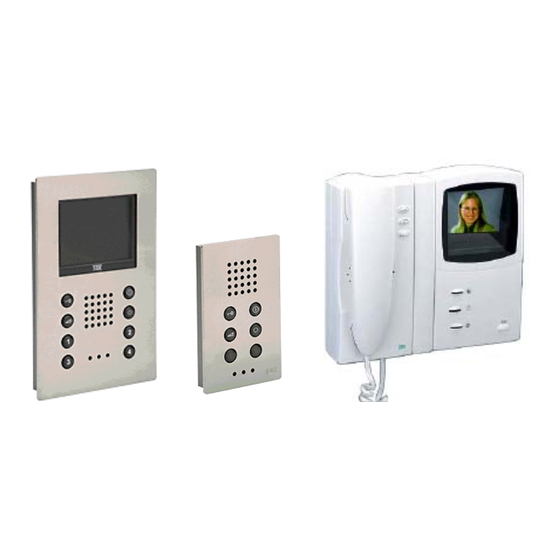
The STR QwikBus™ takes advantage of the latest in digital technology to provide a high tech, high quality color video intercom system operating on a 2 common wire BUS. QwikBus™ video monitor stations all feature a crystal clear 4" LCD Color screen (measured diagonally) and can be surface or flush mounted (with optional UMV1000 flush housing). -
Page 4: Planning The Installation
How many apartments? QwikBus™ can run up to 120 apartments and can exceed that number if specially designed. If you will be installing a larger system please contact Alpha Communications® for assistance. How many apartments will need more than 1 monitor? An apartment can have up to 5 monitors and or audio stations that will ring when the entry button is pressed. - Page 5 The recommended maximum number of monitors on a riser is 10 with each riser originating from the VSP333-2 Control Unit, including from the EVB333 Amplified Splitter(s) if your system requires them. For technical assistance and help determining equipment needed please call: Alpha Communications® at (800) 666-4800 Monday – Friday 8:30- 5:00 pm...
- Page 6 System Notes – 2 wire COLOR with Single Modular Entry A Single Entry Modular system requires the following dipswitch settings on the back of the TSMB3 unit: Switches 4, 5, & 6 identify the entrance number (all OFF = Entrance 1) Switch 3 If the door strike is to be connected to the SP333 (Tö1) = OFF If the door strike is to be connected to the TSMB3 (Tö) = ON For more information refer to Page 10 - Dipswitch Settings.
-
Page 7: Multiple Entry Str Modular Panels
System Notes – 2 wire COLOR with Multiple Modular Entries Multiple Entry Modular systems require the following dipswitch settings on the back of the TSMB3 unit: Switches 4,5, &6 identify the entrance number. In the above example: Entrance #1 = 4 OFF/ 5 OFF/ 6 OFF Entrance #2 = 4 ON / 5 OFF/ 6 OFF Switch 3 If the door strike is connected to the SP333 (Tö2) = OFF (as shown at Entrance 2) If the door strike is connected to the TSMB3 (Tö) = ON (as shown at Entrance 1) -
Page 8: Single Entry Custom Panel
System Notes – 2 wire COLOR with Single Custom Panel Entry The TT33 SPEAKER/MICROPHONE/ CONTROLLER allows you to use QwikBus™ with a custom panel or existing dry contact type entry panel by converting the button presses to a digital signal through an electronic matrix. This matrix is discussed in detail on Page 13. A Single Panel Entry system requires the following dipswitch settings on the TT33 unit: Switches 4, 5, &... -
Page 9: Multiple Entry Custom Panels
System Notes – 2 wire COLOR with Multiple Custom Panel Entries Multiple Custom Panel Entry systems require the following dipswitch settings on the back of the TT33 units: Switch 3 If the door strike is connected to the SP333 (Tö2) = OFF (as shown at Entrance 2) If the door strike is connected to the TT33 (Tö) = ON (as shown at Entrance 1) Switches 4,5, &6 identify the entrance number. -
Page 10: Important Notes On Monitor Riser Connections
System Notes – 2 wire COLOR: Important Information on Monitor Riser Connections This section discusses the proper procedure for connecting monitors on a riser. Although a digital system is very forgiving, it is best to follow these rules during installation to maximize performance and minimize potential problems. -
Page 11: Evb33 Distribution Units
All Monitor BUS lines must be terminated with an End of Line resistor on the last monitor in the run. This is built into each monitor and can be installed by putting a jumper connector on J1. The location of this jumper is illustrated on Page 12. If a BUS is not terminated properly, the electronic characteristics of the line will change resulting in signal degradation and poor video quality. -
Page 12: Dipswitch Settings
Dipswitch Settings – Entries & Door Strikes The QwikBus™ system uses dipswitches for identification of Entry stations, additional cameras, and to enter “Programming Mode”. Entrance Panels must have a unique code so the system knows where the call is coming from and which door to open. -
Page 13: System Camera Options - Lobby Panels, And Observation
Entrance Panel Cameras When using a Modular system, The Modular Camera (KMBC3*) is automatically identified by being connected directly to the TSMB3 and takes the same Entrance number (1-8) of the TSMB3. When using a Custom Panel with a TT33 Speaker/Microphone/Controller, You can use either a pinhole or CCTV type analog camera with it’s own power supply for system video input. -
Page 14: End Of Line Resistors Jumper Locations
BUS End-of-Line Resistors – Jumper Locations For proper system operation, the last video monitor on a BUS riser as well as the last camera on a run must have an End-of-Line Resistors. These resistors are built in to the printed circuit boards and can be connected by installing the jumper on the two pins labeled Usually these jumpers are supplied on all the... -
Page 15: E56 E88 E120 Matrix Extenders
Please refer to the chart below. Additional # of Apartments Components 1 – 23 24 – 55 56 – 87 88 – 119 E120 For systems larger than 119 apartments, contact Alpha Communications for assistance. -
Page 16: The Ic2 Database Chip
The IC2 Database Chip The QwikBus™ system has 8 pin nonvolatile IC chips located on the back of each TSMB3 Speaker Microphone Module (in the Modular style Entry Panels) or TT33 Speaker Microphone Module (in the Custom style Entry Panels). Each unit has this chip which maintains the programming for that specific entry. -
Page 17: Programming The Qwikbus™ System -- Open Voice (Vfs1500/1000)
PROGRAMMING SECTION for OPEN VOICE STYLE NOTE: Depending on your choice of Entry Panel, you will either be using a TT33 or TSMB3 Module. The TT33 and the TSMB3 will both be referred to in this section as the Speaker/Microphone Programming the QwikBus™... -
Page 18: One Man Bench Programming
One Man Bench Programming -- Open Voice (VFS1500/1000 FS1500/1000) If you prefer, the system can be preprogrammed on the bench to minimize your on-site time and eliminate the necessity of a second installer. To do this the inside stations can be connected separately one after another to the Speaker/ Microphone Module (either the TSMB3 or the TT33) using the special programming cable (Part # EMPK-VFS/FS), or just using 2 wires between the BUS terminals of both. -
Page 19: Programming Vfs1500 Stations For Intercommunication
Programming Open Voice VFS1500 for Intercommunication You can install up to five VFS1500 stations and program them for intercommunication in the same residence/ apartment. To program a VFS1500 to ring when one of the numeric buttons on another unit is pressed: 1. -
Page 20: Programming The Qwikbus™ System --Handset (Vhc3033-2)
PROGRAMMING SECTION for HANDSET STYLE NOTE: Depending on your choice of Entry Panel, you will either be using a TT33 or TSMB3 Module. The TT33 and the TSMB3 will both be referred to in this section as the Speaker/Microphone Programming the QwikBus™ System – Handset Style (VHC3033-2 / HT3033) Programming the system is easily done with two installers. -
Page 21: One Man Bench Programming
One Man Bench Programming -- Handset Style (VHC3033-2 / HT3033) If you prefer, the system can be preprogrammed on the bench to minimize your on-site time and eliminate the necessity of a second installer. To do this the inside stations can be connected separately one after another to the Speaker/ Microphone Module (either the TSMB3 or the TT33) using the special programming cable (Part # EMPK-VH/HT) or by running 2 wires between the BUS terminals of both. -
Page 22: Vhc3033-2 Color Handset
USER Operation of the VHC3033-2 Color Handset General Operation After a visitor has rung the bell at the entrance, the monitor will turn on automatically. You can lift the handle and talk with the visitor. You are also able to activate the door opener. When hanging up the handset, the communication will end and the monitor will turn off automatically. -
Page 23: Vfs1500/ Vfs1000 Monitors & Fs1500/Fs1000 Audio Stations
USER Operation of the VFS1000 / VFS1500 Open Voice COLOR Monitor & FS1000/FS1500 Audio only stations General Operation After a visitor has rung the bell at the entrance, the monitor will turn on automatically. You can push the ON/OFF button and talk with the visitor. You are also able to activate the door opener.
Need help?
Do you have a question about the STR QwikBus and is the answer not in the manual?
Questions and answers