Table of Contents
Advertisement
Advertisement
Table of Contents
Troubleshooting

Related Manuals for Citizen CL-S700DT


Summary of Contents for Citizen CL-S700DT
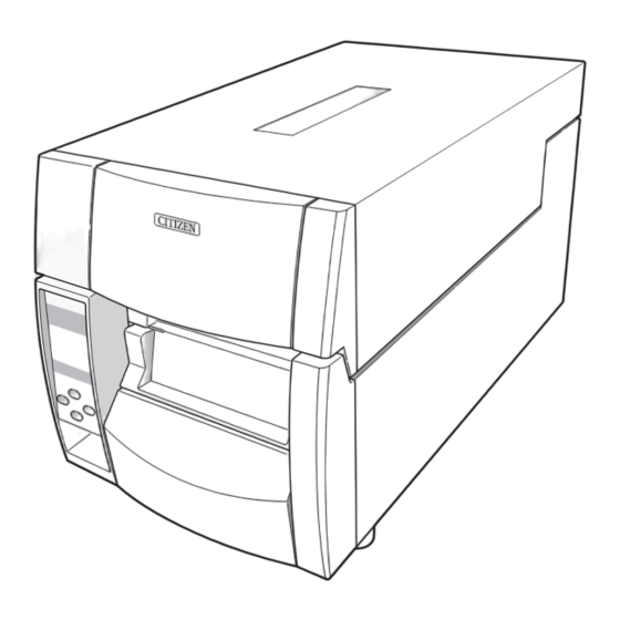
- Page 1 Direct Thermal Barcode & Label Printer CL-S700DT SER'S ANUAL...
-
Page 2: Table Of Contents
CONTENTS Before Operation INTRODUCTION -------------------------------------------------------------------------------- 3 COMPLIANCE STATEMENT FOR EUROPEAN USERS ----------------------------------- 4 FCC COMPLIANCE STATEMENT FOR AMERICAN USERS ------------------------------ 4 EMI COMPLIANCE STATEMENT FOR CANADIAN USERS ------------------------------ 5 ETAT DE CONFORMITE EMI A L’USAGE DES UTILISATEURS CANADIENS --------- 5 IMPORTANT SAFETY INSTRUCTIONS ------------------------------------------------------ 6 NOTICE -------------------------------------------------------------------------------------------- 7 SAFETY INSTRUCTIONS ----------------------------------------------------------------------- 8... -
Page 3: Introduction
INTRODUCTION Thank you for purchasing a Citizen label printer featuring high performance printing, easy media loading and unique front access. ■■■ ■■■ Main Features <Easy Access - Easy Operation> The printer is designed for all day-to-day operations to be accessible from the front of the printer so there is no need to move items near to the printer for access for media loading. -
Page 4: Compliance Statement For European Users
COMPLIANCE STATEMENT FOR EUROPEAN USERS CE marking shows conformity to the following criteria and provisions: Low Voltage Directive (2006/95/EC)/EN60950-1 EMC Directive (2004/108/EC)/EN55022, EN55024, EN61000-3-2 & EN61000-3-3 This product has been tested under EN ISO 7779 and has an acoustic level output no higher than 55db(A). -
Page 5: Emi Compliance Statement For Canadian Users
EMI COMPLIANCE STATEMENT FOR CANADIAN USERS This Class A digital apparatus complies with Canadian ICES-003. This equipment generates and uses radio frequency energy and if not installed and used properly, that is, in strict accordance with the manufacturer's instructions, may cause interference to radio and television reception. -
Page 6: Important Safety Instructions
IMPORTANT SAFETY INSTRUCTIONS • Read all of these instructions and save them for later reference. • Follow all warnings and instructions marked on the product. • Unplug this product from the wall outlet before cleaning. Do not use liquid or aerosol cleaners. Use a damp cloth for cleaning. • Do not use this product near water. • Do not place this product on an unstable cart, stand or table. The product may fall, causing serious damage to the product. • Slots and openings on the cabinet and the back or bottom are provided for ventilation. To ensure reliable operation of the product and to protect it from overheating, do not block or cover these openings. -
Page 7: Notice
• Please contact us if there are any mistakes or ambiguities within this manual. • If there are missing or incorrectly collated pages in this manual, contact us to obtain a new manual. CITIZEN is a registered trademark of CITIZEN HOLDINGS CO., Japan. CITIZEN es una marca registrada de CITIZEN HOLDINGS CO., Japón. Copyright © 2009 by CITIZEN SYSTEMS JAPAN CO., LTD. -
Page 8: Safety Instructions
SAFETY INSTRUCTIONS which must be strictly observed ! • To prevent personal injury or property damage, the following shall be strictly observed. • The degree of possible injury and damage due to incorrect use or improperly following instructions is described below. Indicates a situation which, if not observed and handled Warning properly, could result in death or serious injury. Indicates a situation which, if not observed and handled Caution properly, could result in injury. -
Page 9: General Precautions
General Precautions Caution • Prior to operation, read the safety instructions carefully and observe them. • Do not drop or put foreign matter such as clips and pins into the printer. This may cause problems. • Be careful when moving or carrying the printer. Dropping the printer may cause injury or property damage. • Make sure if you open the top cover, it is opened all the way. If only partially open, the cover could slam shut, possibly causing injury. • When the cover is open, be careful of the corners of the cover. They could cause injury. • Do not open the printer during printing. • When cleaning the surface of the printer case, do not use the cloth that is soaked in thinner, trichloroethylene, benzine, ketone or similar chemicals. • Do not use the printer where there is a lot of oil, iron particles, or dust. • Do not spill liquids or spray insecticide on the printer. • Do not jolt or impact to the printer by stepping on, dropping or hitting the printer. • Operate the control panel properly. A careless, rough handling may cause problems or malfunction. Do not use such sharp-edged tool as a ballpoint pen for operation. • Be careful of the edges of the plates so injury or property damage is possible. -
Page 10: Chapter 1 Setup
Setup Confirmation of Carton Contents Removing the Packing Material The printer is shipped with adhesive tape in place to hold the top cover closed. Simply remove the two pieces of tape on either side of the top cover. Then simply open the cover by lifting up and tipping it backwards. There is another strip of adhesive tape that must be removed which holds the mechanism closed for shipping. -
Page 11: Part Names And Functions
Setup Caution • Be careful when moving or carrying the printer and when taking the printer out of the carton. The printer may cause injury or property damage if dropped. Be sure to grip the printer housing firmly when taking it out of the carton. Do not grip the printer by the foam packing material which may break, causing the printer to drop. - Page 12 Setup Part Names and Functions 1 Media holder guide This guide is moved horizontally to match the media size. The guide can be sliding it from the holder bar. 2 Media holder bar The media is supported by the media holder bar when installed in the printer.
- Page 13 Setup Part Names and Functions 1 Media thickness adjustment screw Media Thickness Adjustment (p.45) It is adjusted to match the thickness of the media. 2 Media width adjustment indicator 3 Media width adjustment knob Media Width Adjustment (p.46) It is adjusted to match the width of the media. 4 Media thickness adjustment indicator 5 Head open lever The head unit can be raised to install media by pushing this lever.
- Page 14 Setup Part Names and Functions 1 Thermal printhead This is the printhead. Avoid touching this with your fingertips and leaving grease or dirt on the printhead surface. 2 Damper arm The media can be installed by raising this arm. The media can be held in place by lowering this arm. 3 Fixed media sensor Installing the Media (p.25) Alternative method to detect the label or tag position.
-
Page 15: Operation Panel
Setup Part Names and Functions Operation Panel POWER ERROR FEED PAUSE STOP MENU 1 LCD display LED Functions (p.21) This displays the operational status of the printer. 2 POWER LED This is lit when the printer power is on. (green) 3 ERROR LED This is lit or flashes when the printer is in an alarm or error status. -
Page 16: Rear View
Setup Part Names and Functions Rear View 1 Interface cover Parallel Interface (p.55) Optional interface board can be installed by removing the interface cover. 2 Serial interface (RS232C) Serial Interface (p.53) This receives serial transmission of data from a host computer. 3 USB interface USB Interface (p.58) This receives USB transmission of data from a host computer. -
Page 17: Connection To Power
Setup Connection to Power The power switch is located on the front of the printer recessed below the control panel1 Check that the power switch is turned OFF1 Insert the power cord in to the inlet on the printer1 Insert the plug of the power cord in the AC outlet1 Power Switch AC Outlet Power Cord Inlet... -
Page 18: Connection To A Computer
Setup Connection to a Computer This product has two interfaces that can be used to receive printing data: a serial port (RS232C) and a USB port (USB1.1). An optional internal network interface or parallel interface (IEEE1284, Non-L. P. S.) can be added by your dealer. -
Page 19: Chapter 2 Printer Operation
Printer Operation Printer Operation Power ON/OFF Turning on the power The power switch is conveniently located at the front of the printer for easy access during normal operation1 It is in the recess underneath the control panel so it cannot be accidentally operated by mistake1 The POWER LED is lit1 Operation Panel... -
Page 20: Normal Operating Mode
Printer Operation Normal Operating Mode When the power is turned on, the printer enters normal operating mode. Menu Setup Mode (p.28) The control keys activate the following functions. On Line Ready POWER ERROR FEED PAUSE STOP MENU 1 PAUSE key: Temporarily pauses printing • When this key is pushed once, the LCD indicates "Pause" and the printer temporarily pauses. -
Page 21: Led Functions
Printer Operation Normal Operating Mode LED Functions 1 POWER LED It lights up when printer power is POWER ERROR turned on. (green) FEED 2 ERROR LED PAUSE STOP This is lit or flashes when the printer is in error status. (orange) MENU Table of Alarm and Error Indications In addition to normal operating mode, when an abnormal condition is... -
Page 22: Setting The Media
Printer Operation Setting the Media Media Sizes The position of label and tag media is sensed by either a transparent sensor or a reflective sensor. Transparent sensor: Detects the gaps between label media and notches of tag media Reflective sensor: Detects the black mark Size of media Label media... -
Page 23: Printer Operation
Printer Operation Setting the Media When Using Front Sensors Minimum value mm (in) Maximum value mm (in) Label width 7.62 (0.3) 118.00 (4.65) Liner width 25.40 (1.0) 118.00 (4.65) Left end of label 2.54 (0.10) Gap between labels 2.54 (0.10) 812.80 (32.00) Label length... -
Page 24: Installing The Media
Printer Operation Setting the Media Installing the Media Push the large blue head-open lever to release the head unit, and then lift the damper arm by hand as shown below1 Damper arm open lever Head unit Damper arm Large blue-head open lever Firstly, slide the two black plastic parts of the media holder Media Sizes (p.22) assembly together1 Ensure correct alignment of the guide... - Page 25 Printer Operation Setting the Media Set the media roll and media holder in to the printer as shown above1 It is advisable to pull a length of media forwards and through the mechanism ready for later positioning1 Move the media roll so it is touching the left side of the housing1 Then slide the black movable media guide so it is touching the media on the right side1 Note: Do not try to hold the media too tightly with these guides as it will...
-
Page 26: Mode Settings
Printer Operation Mode Settings Turning on the power while pressing keys in the following combinations Operation Panel (P.15) starts various functions. Mode Key operation HEX dump mode Turning power on while pushing the STOP key. Self print mode Turning power on while pushing the FEED key. Menu list print mode and Turning power on while pushing the MENU key. -
Page 27: Self Print Mode
Printer Operation Mode Settings Self Print Mode Performing a self test print is an easy way to check on the state of printer settings and printing quality. Install the media as explained in "Installing the Media" and then operate the printer as follows. ... - Page 28 Printer Operation Mode Settings Menu Setup Mode If the MENU key is pressed while the printer is in the On Line Ready state, the printer enters menu setup mode. In this mode, the printer's configuration can be changed using the operation panel. During menu setting mode, the LCD indicates the current menu settings and the key function.
- Page 29 Printer Operation Mode Settings Example of changing a menu This is an explanation of the method of changing the set value of print darkness from "12" to "14" in a case where the main menu is "Page Setup" and the sub menu is "Print Darkness". Entering Menu Setup Mode1 Ensure LCD displays "On Line Ready"1 Then press the MENU key to enter 'menu setup mode' where the printers settings...
- Page 30 Printer Operation Mode Settings Entering Sub menu1 Press the key1 The currently set item, "Print Speed", is displayed1 Page Setup Print Speed Exit Enter The following are the functions of each key. key: displays the previous sub menu ...
- Page 31 Printer Operation Mode Settings Save Changes to Settings1 Unless you save your settings, your changes will be lost when you turn off the printer1 To Save Changes 1 Press the key twice to display the Save Settings message "Save Settings No-Discard". No-Discard Exit Enter...
- Page 32 USB VCOM Protocol : Auto <Example of CL-S700DT Datamax® emulation selected> Note: Citizen continually enhances its printers with new options and settings based on our customer's requests. Extra or changed menu items may appear on the above print out in some cases.
-
Page 33: Print Darkness
10.00inch 10.00inch 10.00inch Settings Lock Keyboard Lock Control Code Emulation Select [After Print Menu] AutoConfigure Function Select Tear Tear Tear Paper Position +0.00inch +0.00inch +0.00inch Menu Key Action Enters Menu Enters Menu Enters Menu <Example of CL-S700DT Datamax® emulation selected>... -
Page 34: Menu Setting
Printer Operation Mode Settings [Datamax® Emulation] Menu Setting Table Page Setup Menu - allows you to change settings related to the media or print quality. System Setup Menu - allows you to change settings for the printer hardware and basic control systems. After Print Menu - changes how the printer reacts after the label has been printed. - Page 35 Printer Operation Mode Settings [Datamax® Emulation] Top Menu Sub Menu Default Menu Remarks Max Media Length 10.00 inch 1.00 to 50.00 inch Sets the maximum media length. [Max Media Len] 254.0 mm 25.4 to 1270.0 mm Settings Lock Prevents a command changing the set value. Keyboard Lock Prevents a change by a key operation.
- Page 36 Printer Operation Mode Settings [Datamax® Emulation] Top Menu Sub Menu Default Menu Remarks Menu Key Action Enters Menu Enters Menu Sets the menu key action. Repeat Last Set Enters Menu: Repeat Last One Enters the menu setup mode. Repeat Last Set: Repeats the number of copies.
- Page 37 Printer Operation Mode Settings [Datamax® Emulation] Top Menu Sub Menu Default Menu Remarks Service Counter – ****.*** km Displays the service counter. Cut Counter – – Displays the cut count. Sensor Monitor – *.* V Displays the sensor level. Option Interface –...
- Page 38 Printer Operation Mode Settings [Zebra® Emulation] Zebra® Emulation Top Menu Sub Menu Default Menu Remarks Page Setup Print Speed 7 IPS 2 to 7 IPS Printing speed setting. Print Darkness 00 to 30 Adjusting print darkness. Darkness Adjust -10 to 10 Fine adjustment of darkness commands.
- Page 39 Printer Operation Mode Settings [Zebra® Emulation] Top Menu Sub Menu Default Menu Remarks After Print AutoConfigure Automatically configures optional devices. [Auto Config] On..AutoConfigure enabled (Regardless of whether Function Select is set, if a peeler or cutter is installed, each mode is set automatically.) Off ..AutoConfigure disabled (A peeler of cutter is installed, but to not operate...
- Page 40 Printer Operation Mode Settings [Zebra® Emulation] Top Menu Sub Menu Default Menu Remarks RS-232C Stop bit 1 bit 1 bit Setting the stop bit for the serial interface. [RS-232C Stopbit] 2 bits RS-232C X-ON On Yes On Yes Selectively setting the X-ON flow control of Off No the serial interface.
-
Page 41: Emulation Auto-Detection
Printer Operation Emulation Auto-Detection Menu Setup Mode Ordinarily emulation switching is conducted in the Menu Setup mode. (p.29, p34, p38) However, switching can also be conducted using the Emulation Auto- Detection function outlined below. The following message is displayed on the LCD when the Zebra® emulation (ZPI2) command is detected during Datamax®... -
Page 42: Chapter 3 Printer Adjustments
Printer Adjustments Sensor Adjustments and Calibration The sensing level of both the transparent (see thru) and reflective sensors is adjusted separately and independently. Firstly, the sensor type must be selected using the Sensor Method Selection shown below. Then the adjustment and calibration of the sensor can be made. Entering Sensor Adjustment Mode Turn on the power while pushing the PAUSE key, FEED key, and STOP key simultaneously1... -
Page 43: Printer Adjustments
Printer Adjustments Sensor Adjustments and Calibration Adjusting the Transparent sensor The transparent sensor is selected1 Installing the Media (p.24) Install only the liner media (label backing paper) with the Quick Sensor Selection Method (Transparent Reflective) label media removed so that it will pass between the platen (p.42) roller and the media sensor1 (Be careful that media with black marks does not pass the media sensor1) Then close the... - Page 44 Printer Adjustments Sensor Adjustments and Calibration Adjusting the Reflective sensor Quick Sensor Selection Method The reflective sensor is selected1 (Transparent Reflective) With the reflective sensor selected, install the label media so (p.42) that it is between the platen roller and the media sensor1 Be careful that black mark and media gap do not pass the media sensor.
-
Page 45: Media Thickness Adjustment
Printer Adjustments Media Thickness Adjustment The printer is already factory-set to the requirements of proper print quality Installing the Media (p.24) while using the recommended labels. If the print quality is inferior because of the different type of media, adjust the printhead position in the following manner: When using standard labels, or thermal media Self Print Mode (p.27) Looking in at the media thickness check window, reset the printhead offset so that it comes to the center line (middle of... -
Page 46: Media Width Adjustment
Printer Adjustments Media Width Adjustment The printer is already factory-set to the value of media width: 112 mm Installing the Media (p.24) (4.4 in). When you use narrow media, adjust the printhead pressure in the following: Looking in at the check window on the upper frame, align the mark (the left end of white plastic) with the width of media by turning the media width adjustment knob1 (The printhead must be closed1) -
Page 47: Cleaning
Printer Adjustments Cleaning Wipe off any foreign objects such as media dust, dirt and adhesive substances built up around the printhead and platen with the head cleaning pen (head cleaner) provided, and use a soft cloth soaked in ethyl alcohol for the platen etc. It is particularly important to clean the thermal printhead after printing on thermal media for long periods, which will guarantee the print quality and extend the life of the thermal printhead. -
Page 48: Chapter 4 Troubleshooting
Troubleshooting This chapter explains corrective actions taken when the printer malfunctions or when an error message is displayed. Items to check when a malfunction occurs When the printer malfunctions during operation, take corrective action with reference to the following table. If the corrective action does not solve the problem, consult with the service personnel at the dealer where you purchased the printer. -
Page 49: Troubleshooting
Troubleshooting Indication Check Corrective action The printer is not 4) Is the thermal 4) If it is dirty, remove the dirt with printing neatly. printhead dirty? the attached head cleaner. Is a label stuck to the If a label is stuck to the head, head. -
Page 50: Appendixes
Appendixes Specifications Item Description Printing Printing method Thermal transfer/Direct thermal Resolution Main scanning line density: 203 dots/inch (8 dots/mm) Sub- scanning line density: 203 dots/inch (8 dots/mm) Head 864 dots (printable dots: 832 dots) Max. print width 104 mm 4.1 inch Max. - Page 51 Appendixes Specifications Item Description Font 1. Five kinds of fixed pitch font (for Zebra® emulation) • Overseas, English fonts and European fonts 2. OCR fonts OCR-A, OCR-B 3. Proportional font CG Triumvirate Condensed Bold 4. True type™ rasterizer Symbol set PC866U Ukraina , PC Cyrillic, ISO 60 Danish/Norwegian, DeskTop, ISO 8859/1 Latin 1, ISO 8859/2 Latin 2, ISO 8859/9 Latin 5, ISO 8859/10 Latin 6, ISO 8859/7 Latin/Greek, ISO 8859/15 Latin 9, ISO 8859/5 Latin/Cyrillic, ISO 69: French, ISO 21: German, ISO 15: Italian, Legal,...
- Page 52 Appendixes Specifications Item Description Environment Operating temperature Operating temp. 0 to 40°C, humidity 30 to 80%, condensation free conditions: (Conditions: ventilation, and natural convection) Storage temperature Temp. -20 to 60°C, humidity 5 to 85% conditions: (Conditions: ventilation, and natural convection) Operating assurance temperature Printing assurance temperature Humidity %...
-
Page 53: Interfaces
Appendixes Interfaces This printer is connected to a computer and prints according to commands sent from the computer. There are three types of computer interfaces, and these are connected to devices suited to each type of interface. The printer can also be connected to a computer by the optional Ethernet. - Page 54 Appendixes Interfaces XON/XOFF Protocol Requirements to output X-ON code • Communication is possible when the power is on. • When the receive buffer has less than 128 bytes available, XOFF code is output, then the receive buffer has at least 1024 bytes available. Requirements to output the X-OFF code • When the receive buffer has less than 128 bytes available Receive bu er 16K bytes XOFF 128 bytes 1024 bytes DTR Protocol Conditions when the DTR signal is "Ready (High)" All the following conditions are satisfied.
-
Page 55: Parallel Interface
Appendixes Interfaces Parallel Interface Specifications Transmission mode 8-bit parallel data Receive buffer size 16K bytes Compatible mode Transmission modes It is an asynchronous forward direction of the byte width (from host to printer) channel, and the interface line of the data is operated in accordance with signal line definitions of Centronics. - Page 56 Appendixes Interfaces Parallel port status signals when an error occurs The status of a signal line will not be changed in bi-directional mode such as nibble or ECP mode. Error Change in the status of a signal line in compatible mode Paper end Busy : L ...
- Page 57 Appendixes Interfaces [While receiving INIT signal] Min. 10 to 15µsec *Init BUSY *Ack *Fault SELECT Note: If the *Init signal does not have width of 10 to 15µsec or more, it cannot act as an Init signal. If it is lower, the *Init signal is ignored. BUSY starts up when the *Init signal is perceived.
-
Page 58: Usb Interface
Appendixes Interfaces USB Interface Specifications Standards Complies with Universal Serial Bus Specification Transmission speed Compatible with 12Mbps (full speed) transmission Receive buffer 16K bytes Connector DUSB DUSB-BRA42-T11(DDK) Signal line and pin arrangement Pin No. Signal code Signal Function VBUS USB power USB power (+5V) Signal line + + signal line... -
Page 59: Connecting The Optional Interface Board
Appendixes Connecting the Optional Interface Board Caution Always turn off the power to the printer before connecting the optional interface board. Do not pull the interface cable out with unnecessary force. This will cause an accident. Replacement Method Remove the screws (2) of the interface cover then pull the interface cable towards you1 When you do this, be careful not to perform any unreasonable operations that will damage the connecting cable and do not pull the cable too much1 If... - Page 60 Appendixes Connecting the Optional Interface Board Insert the interface board into the printer so that the connecting cable does not catch on the printer, then use the screws (2) that you removed to anchor the bracket1 Interface Board Rear Side Screw...
- Page 61 If you want to dispose this product, do not mix with general household waste. There is a separate collection systems for used electronics products in accordance with legislation under the WEEE Directive (Directive 2002/96/EC) and is effective only within European Union. Wenn Sie dieses Produkt entsorgen wollen, dann tun Sie dies bitte nicht zusammen mit dem Haushaltsmüll.
- Page 62 363 Van Ness Way, Suite 404 Torrance, CA 90501. USA Tel: (310) 781-1460 Fax: (310) 781-9152 http://www.citizen-systems.com Mettinger Strasse 11 Park House, 643-651 Staines Road D-73728, Esslingen Feltham, Middlesex, TW14 8PA Germany United Kingdom Tel: +49 (0) 711 3906 420...
Need help?
Do you have a question about the CL-S700DT and is the answer not in the manual?
Questions and answers