Table of Contents
Advertisement
Advertisement
Table of Contents

Related Manuals for Citizen CL-E700 Series


Summary of Contents for Citizen CL-E700 Series
- Page 1 Thermal Transfer Barcode & Label Printer CL-E700 Series SER'S ANUAL...
-
Page 2: Table Of Contents
CONTENTS INTRODUCTION ..........................3 COMPLIANCE STATEMENT FOR EUROPEAN USERS ............5 GS MARK STATEMENT ........................5 FCC COMPLIANCE STATEMENT FOR AMERICAN USERS ........... 5 EMI COMPLIANCE STATEMENT FOR CANADIAN USERS ........... 6 ETAT DE CONFORMITE EMI A L’USAGE DES UTILISATEURS CANADIENS ....6 IMPORTANT SAFETY INSTRUCTIONS .................. -
Page 3: Introduction
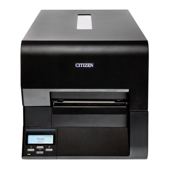
INTRODUCTION Thank you for purchasing the CITIZEN CL-E700 series printer. This printer is compatible with the maximum media width (118 mm or 4.65 inch), which has been developed for a wide range of applications such as labels, tags and tickets. -
Page 4: Adjustable Sensors
<Adjustable sensors> The adjustable media sensors - which allow the sensors to be positioned in different locations across the media - are standard features making the printer ideal for use with special media. <Installation> The interface, power switch etc. are installed towards the back and the top cover opens and closes vertically so that the sides of the printer are not restricted. -
Page 5: Compliance Statement For European Users
COMPLIANCE STATEMENT FOR EUROPEAN USERS CE marking shows conformity to the following criteria and provisions: Low Voltage Directive (2006/95/EC, formerly 73/23/EEC)/EN60950-1 EMC Directive (2004/108/EC, formerly 89/336/EEC)/EN55022, EN55024, EN61000-3-2 & EN61000-3-3 GS MARK STATEMENT This product has been tested under EN ISO 7779 and has an acoustic level output no higher than 70db(A). -
Page 6: Emi Compliance Statement For Canadian Users
EMI COMPLIANCE STATEMENT FOR CANADIAN USERS This Class A Information Technology Equipment (ITE) complies with Canadian CAN ICES- 3(A)/NMB-3(A). This equipment generates and uses radio frequency energy and if not installed and used properly, that is, in strict accordance with the manufacturer’s instructions, may cause interference to radio and television reception. -
Page 7: Important Safety Instructions
IMPORTANT SAFETY INSTRUCTIONS • Read all of these instructions and save them for later reference. • Follow all warnings and instructions marked on the product. • Unplug this product from the wall outlet before cleaning. Do not use liquid or aerosol cleaners. Use a damp cloth for cleaning. -
Page 8: Notice
Visit the following site to get documentation, drivers, utilities, and other information. http://www.citizen-systems.co.jp/english/support/index.html CITIZEN is a registered trademark of CITIZEN HOLDINGS CO., Japan. CITIZEN es una marca registrada de CITIZEN HOLDINGS CO., Japón. Copyright © 2014 by CITIZEN SYSTEMS JAPAN CO., LTD. -
Page 9: Safety Instructions
SAFETY INSTRUCTIONS which must be strictly observed ! • To prevent personal injury or property damage, the following shall be strictly observed. • The degree of possible injury and damage due to incorrect use or improperly following instructions is described below. Indicates a situation which, if not observed and handled Warning properly, could result in death or serious injury. -
Page 10: General Precautions
General Precautions Caution • Prior to operation, read the safety instructions carefully and observe them. • Do not drop or put foreign matter such as clips and pins into the printer. This may cause problems. • Be careful when moving or carrying the printer. Dropping the printer may cause injury or property damage. -
Page 11: Chapter 1 Setup
Chapter 1 Setup Chapter 1 Setup Confirmation of Carton Contents Check that the following accessories are included with the printer in the carton. Ribbon holder Sample ribbon Paper core (for ribbon) Head cleaner Media holder guide Media holder bar Test label media Power cord CD-ROM Quick-start guide... - Page 12 Chapter 1 Setup Confirmation of Carton Contents Caution • Be careful when moving or carrying the printer and when taking the printer out of the carton. The printer may cause injury or property damage if dropped. Be sure to grip the printer housing firmly when taking it out of the carton.
-
Page 13: Part Names And Functions
Chapter 1 Setup Part Names and Functions Front View 1 Top cover window The amount of ribbon and media remaining can be checked through this window. 2 Top cover Is opened vertically to set media or ribbon. 3 Operation panel Operation panel (p.18) This is used to make changes and adjustments to the printer and its configuration... - Page 14 Chapter 1 Setup Part Names and Functions Inside the printer 1 Media holder guide This guide is moved horizontally to match the media size. The guide can be sliding it from the holder bar. 2 Media holder bar The media is supported by the media holder bar when installed in the printer.
- Page 15 Chapter 1 Setup Part Names and Functions 1 Large blue-head open lever The head unit can be raised to install media by pushing this lever. It locks the head unit during printing. 2 Media width adjustment dial Media Width Adjustment It is adjusted to match the width of the media.
-
Page 16: Thermal Printhead
Chapter 1 Setup Part Names and Functions 1 Thermal printhead This is the printhead. Avoid touching this with your fingertips and leaving grease or dirt on the printhead surface. 2 Sensor arm The media can be installed by raising this arm. The media can be held in place by lowering this arm. - Page 17 Chapter 1 Setup Part Names and Functions 1 Rear (feeding side) ribbon tension adjustment knob Ribbon Tension Adjustment (p.61) The adjustment is done according to the width of the ribbon to be used. It is adjusted when slippage or wrinkling appears in the ribbon. 2 Ribbon guide adjusting cam Ribbon guide adjustment (p.65)
- Page 18 Chapter 1 Setup Part Names and Functions Operation panel 1 LCD display Normal Operating Mode (p.23) This displays the operational status of the printer and the menu settings. 2 Pause key This temporarily stops printing. 3 LED LED Functions (p.24) This is lit when the printer power is on.
- Page 19 Chapter 1 Setup Part Names and Functions Rear View 1 Power switch Power ON/OFF (p.22) The is the power switch for the printer. 2 Power cord inlet Connection to Power (p.20) The connector of the enclosed power cord is connected here. 3 Fanfold paper insertion slot If you want to use fanfold paper, insert the media into this slot from outside the printer.
-
Page 20: Connection To Power
Chapter 1 Setup Connection to Power 1. Check that the power switch to the printer is turned OFF. 2. Connect the connector of the power cord to the power cord inlet on the printer. 3. Insert the plug of the power cord in the AC outlet. AC Outlet Power Cord Inlet Caution... -
Page 21: Connection To A Computer
USB Interface Cable Network cable Note: If an optional parallel port (IEEE1284), serial port (RS232C) or Wireless LAN port is used, contact your Citizen Systems dealer. Caution Connect only the LAN Connector to the LAN receptacle. (Do not connect the external cable which may be applied... -
Page 22: Chapter 2 Printer Operation
Chapter 2 Printer Operation Chapter 2 Printer Operation Power ON/OFF Turning on the power 1. Turn on the power switch on the back of the printer. 2. The LED are lit. Power Switch Turning off the power 1. Turn off the power switch on the back of the printer. 2. -
Page 23: Normal Operating Mode
Chapter 2 Printer Operation Normal Operating Mode Menu Setup Mode (p.35) When the power is turned on, the printer enters normal operating mode. The control keys activate the following functions. 1 MENU key: Performs selection of Menu Setup Mode and re-printing •... -
Page 24: Led Functions
Chapter 2 Printer Operation Normal Operating Mode LED Functions In addition to normal operating mode, when an abnormal condition is detected in the printer, an alarm sounds and the LED lights up (red) to indicate the type of error. The LCD indicates the error message. -
Page 25: Setting The Media
Chapter 2 Printer Operation Setting the Media Media Sizes The position of label and tag media is sensed by either a transparent sensor or a reflective sensor. Transparent sensor: Detects the gaps between label media and notches of tag media Reflective sensor: Detects the black mark Label media... -
Page 26: Installing The Media
Chapter 2 Printer Operation Setting the Media Installing the Media 1. Push the large blue-head open lever to release the head unit, and then lift the sensor arm by hand as shown below. Head unit Sensor arm Large blue-head open lever 2. - Page 27 Chapter 2 Printer Operation Setting the Media 5. The path of the media varies according to the orientation of the printing surface. Set the media according to the diagram shown below. Media damper Printing surface is facing Printing surface is facing outwards inwards Pass below the media damper...
-
Page 28: Setting Sensor Positions
Chapter 2 Printer Operation Setting the Media 6. Setting sensor positions When using a transparent sensor Sensor Selection Method Move the bottom sensor close to the center of the width of the media, (Transparent Reflective) (p.55) then align the upper sensor marker and the bottom sensor marker Adjusting the Transparent sensor (white) using the movable media guide. - Page 29 Chapter 2 Printer Operation Setting the Media 7. Lift the sensor arm up temporarily and adjust the media guide. Align the media with the left fixed media guide, align the right movable media guide with the media width, and lower the sensor arm. Movable media guide Fixed media guide...
-
Page 30: Setting The Ribbon
Chapter 2 Printer Operation Setting the Ribbon The following kinds and sizes of ribbons can be used. Types ............Inside wound and outside wound ribbon Recommended ribbon ......B110A Ricoh Sample ribbon ......... B110TI Ricoh Max. ribbon width ........114.0 mm (4.50 inch) Min. - Page 31 Chapter 2 Printer Operation Setting the Ribbon 2. Install the unused ribbon and holder in to the rear ribbon drive unit. ② ① 3. Push the large blue-head open lever to release the head unit. Pull out the ribbon from the bottom of the head unit to the ribbon winding side.
- Page 32 Chapter 2 Printer Operation Setting the Ribbon 5. Set the ribbon holder on which the paper core has been set in the ribbon drive unit, then rotate it in the direction shown by the arrow to remove slack and wrinkles from the ribbon. 6.
-
Page 33: Mode Settings
Chapter 2 Printer Operation Mode Settings Turning on the power while pressing keys in the following combinations Operation panel (p.18) starts various functions. Mode Key operation HEX dump mode Turning power on while pushing the Stop key. Self print mode Turning power on while pushing the Feed key. -
Page 34: Self Print Mode
Chapter 2 Printer Operation Mode Settings Self Print Mode Performing a self test print is an easy way to check on the state of printer setting and printing quality. Install the media as explained in “Installing the Media” and then operate the printer as follows. Setting the Media (p.25) ... - Page 35 Chapter 2 Printer Operation Mode Settings Menu Setup Mode If the MENU key is pressed while the printer is in the Ready state, the printer enters menu setup mode. In this mode, the printer’s configuration can be changed using the operation panel. During menu setting mode, the LCD indicates the current menu settings and the key function.
- Page 36 Chapter 2 Printer Operation Mode Settings Example of changing a menu This is an explanation of the method of changing the set value of print darkness from “10” to “12” in a case where the main menu is “Page Setup” and the sub menu is “Print Darkness”.
- Page 37 Chapter 2 Printer Operation Mode Settings 2. Entering Sub menu. Press the Stop key ( g ). The currently set item, “Print Speed”, is displayed.. Page Setup Print Speed The following are the functions of each key. MENU key : displays the previous sub menu Feed key ( n ) : displays the next sub menu Pause key ( e ) : displays the values set by the selected sub menu Stop key ( g )
- Page 38 Chapter 2 Printer Operation Mode Settings 6. Save Changes to Settings. Unless you save your settings, your changes will be lost when you turn off the printer. To Save Changes 1 Press the Pause ( e ) key twice Save Settings to display the message “Save No - Discard Settings No-Discard”.
-
Page 39: Machine Information
RS-232C X-ON : Yes NOTE: • Citizen continually enhances its printers with new options and settings based on our customer’s requests. Extra or changed menu items may appear on the above print out in some cases. • The set value of “Option Interface” is printed even if optional interface is... - Page 40 Chapter 2 Printer Operation Mode Settings Global Configuration Sets The printer can store three sets of configuration settings that can be recalled quickly and easily. Each “Config Set” (1, 2 or 3) can contain completely different configuration settings for all menu parameters. For example, “Config Set 1”...
- Page 41 Chapter 2 Printer Operation Mode Settings Menu Setting Table Page Setup Menu - allows you to change settings related to the media or print quality. System Setup Menu - allows you to change settings for the printer hardware and basic control systems. After Print Menu - changes how the printer reacts after the label has been printed.
- Page 42 Chapter 2 Printer Operation Mode Settings [Datamax® Emulation] Top Menu Sub Menu Default Menu Remarks System Setup Sensor Monitor – – Displays level of sensor that is currently selected. Sensor Level 1.7V 0.0V to 3.3V Selects threshold of the sensor. Paper End Level 3.00V 0.01 to 3.30V...
- Page 43 Chapter 2 Printer Operation Mode Settings [Datamax® Emulation] Top Menu Sub Menu Default Menu Remarks After Print Auto Configure Automatically configures optional devices. [Auto Config] On ..AutoConfigure enabled (Regardless of whether Function Select is set, if a peeler or cutter is installed, each mode is set automatically.) Off ..AutoConfigure disabled (A peeler of cutter is installed, but to not operate...
- Page 44 Chapter 2 Printer Operation Mode Settings [Datamax® Emulation] Top Menu Sub Menu Default Menu Remarks Interfaces USB Device Class Printer Printer Selects the USB device class. [USB Device Clas] VCOM USB VCOM Protocol Auto Auto Selects the protocol (flow control) when [VCOM Protocol] operating USB VCOM.
- Page 45 Chapter 2 Printer Operation Mode Settings [Datamax® Emulation] Top Menu Sub Menu Default Menu Remarks Network Address ** – 000.000.000.000 to Setting fixed IP address of the LAN board. 255.255.255.255 Subnet Mask ** – 000.000.000.000 to Setting fixed subnet mask value of the LAN 255.255.255.255 board.
- Page 46 Chapter 2 Printer Operation Mode Settings [Datamax® Emulation] Top Menu Sub Menu Default Menu Remarks Test Mode Print Pattern Current Config Current Config Executes the test pattern. Global Config Sample Head Check Executes head check. Factory Default Initializes the set values of the configuration set to the state when the unit was shipped from the factory.
- Page 47 Chapter 2 Printer Operation Mode Settings For Zebra® Emulation Top Menu Sub Menu Default Menu Remarks Page Setup Print Speed 6 IPS 2 to 8 IPS Printing speed setting. (7 or 8 IPS only in Direct Thermal mode.) (2 to 6 IPS with optional peeler.) Print Darkness 00 to 30 Adjusting print darkness.
- Page 48 Chapter 2 Printer Operation Mode Settings [Zebra® Emulation] Top Menu Sub Menu Default Menu Remarks Keyboard Lock Prevents a change by a key operation. Hold down the Menu Key for at least 4 seconds to enter the Menu Setup Mode when setting the “On”...
- Page 49 Chapter 2 Printer Operation Mode Settings [Zebra® Emulation] Top Menu Sub Menu Default Menu Remarks Peel Wait Delay * 0.1 sec 0.1 to 2.0 sec Sets the Peel Wait Delay. Displays only machines with a peeler installed. Paper Position 0.00 inch Peel/Cut/Tear Off Adjusts the stop position.
- Page 50 Chapter 2 Printer Operation Mode Settings [Zebra® Emulation] Top Menu Sub Menu Default Menu Remarks Option RS-232C Baud 9600 115200 Setting the baud rate of the serial interface. Interfaces 57600 • All settings related to the interface are 38400 enabled after the power is reconnected. 19200 9600 4800...
- Page 51 Chapter 2 Printer Operation Mode Settings [Zebra® Emulation] Top Menu Sub Menu Default Menu Remarks Machine Model Number – CL-E*** Displays the model name. Information Boot Version – Displays the boot version [Machine Info] ROM Version – ******** Displays the ROM version. ROM Date –...
-
Page 52: Quick Setup Of The Print Method
Chapter 2 Printer Operation Quick Setup of the Print Method Menu Setup Mode (p.35) The print method (thermal transfer method/direct thermal method) can be set using operation panel in addition to Menu Setup mode. Caution Be sure to always shut off the operation of print before changing a setting. -
Page 53: Emulation Auto Detect: Cross-Emulation
Chapter 2 Printer Operation Emulation Auto Detect: Cross-Emulation Ordinarily emulation switching is conducted in the Menu Setup mode. Menu Setting Table (p.41) However, switching can also be conducted using the Emulation Auto- Detection function outlined below. The following message is displayed on the LCD when the Zebra® emulation (ZPI2) command is detected during Datamax®... - Page 54 Chapter 2 Printer Operation Emulation Auto Detect: Cross-Emulation Note: • The Emulation Auto-Detection function will not work if the “Emulation Auto Detect” command in the Sub Menu in the “System Setup” in the Top Menu is set to “Off ”. (The command is set to “On”...
-
Page 55: Chapter 3 Printer Adjustments
Chapter 3 Printer Adjustments Chapter 3 Printer Adjustments Sensor Adjustments The sensing level of both the transparent (see thru) and reflective sensors is adjusted separately and independently. Firstly, the sensor type must be selected using the Sensor Method Selection shown below. Then the adjustment and calibration of the sensor can be made. - Page 56 Chapter 3 Printer Adjustments Sensor Adjustments Adjusting the Transparent sensor 1. The transparent sensor is selected. Installing the Media (p.26) Sensor Selection Method 2. Install only the liner media (label backing paper) with the (Transparent Reflective) label media removed so that it will pass between the platen (p.55) roller and the media sensor.
- Page 57 Chapter 3 Printer Adjustments Sensor Adjustments Adjusting the Reflective sensor 1. The reflective sensor is selected. Installing the Media (p.26) Sensor Selection Method 2. With the reflective sensor selected, install the label media (Transparent Reflective) so that it is between the platen roller and the media sensor. (p.55) Be careful that black mark and media gap do not pass the media sensor.
- Page 58 Chapter 3 Printer Adjustments Sensor Adjustments 3. If the Pause Key is pressed then released while the Feed key is continually pressed, the sensor is automatically adjusted. Sensor Cal Mode Executing Hold Press/Release 4. When automatic adjustment stops normally, “Succeeded” is displayed by the LCD.
-
Page 59: Media Thickness Adjustment
Chapter 3 Printer Adjustments Media Thickness Adjustment It may be necessary to adjust the printer according to the thickness of Installing the Media (p.26) the media being used. This can be done easily by rotating the media adjustment dial to improve the print quality. •... -
Page 60: Media Width Adjustment
Chapter 3 Printer Adjustments Media Width Adjustment The head pressure varies according to the width of the media being Installing the Media (p.26) printed. The head pressure balance must be adjusted according to media width so that constant head pressure is applied to the head. With this printer, it can be adjusted easily by turning the media width adjustment dial. -
Page 61: Adjusting The Ribbon
Chapter 3 Printer Adjustments Adjusting the Ribbon If the width of the ribbon changes, a constant pressure will be applied Setting the Ribbon (p.30) on the guide roller etc. Therefore, it is required to adjust the tension or balance according to the ribbon width. If the ribbon wrinkles or slips, adjust the tension and balance. - Page 62 Chapter 3 Printer Adjustments Adjusting the Ribbon 2. Adjustment in the feeding side (rear side) Ribbon on the feeding side Rear ribbon tension adjustment knob Fixing pin 1 Press and turn the rear ribbon tension adjustment knob while the ribbon on the feeding side is fixed. 2 Refer to the table given below and fix by aligning the scale of rear ribbon tension adjustment knob to the fixing pin.
- Page 63 Chapter 3 Printer Adjustments Adjusting the Ribbon Ribbon Balance Adjustment Self Print Mode (p.34) Do this adjustment by turning the front ribbon left-right balance adjustment knob. If the ribbon is wrinkled, adjust it as follows. The scale is usually aligned with the center. Front ribbon left-right balance adjustment knob 1.
- Page 64 Chapter 3 Printer Adjustments Adjusting the Ribbon 2. Make adjustment according to the position at which looses occur in the ribbon, by using the following procedure. In case of looseness on the side opposite the adjustment knob Turn the front adjustment knob to the left to remove the looseness, then make a test print to ensure that the ribbon is not wrinkled.
-
Page 65: Ribbon Guide Adjustment
Chapter 3 Printer Adjustments Adjusting the Ribbon Ribbon guide adjustment Prevent occurrence of wrinkles on the ribbon by adjusting the inclination of ribbon guide at the rear side (feeding side). If looses occur in the feeding side ribbon, adjust by using the following procedure. - Page 66 Chapter 3 Printer Adjustments Adjusting the Ribbon When ribbon loosing occurs in the front ribbon left-right balance adjustment knob side Lower the ribbon guide adjustment cam and increase the inclination of the ribbon guide shaft of the side where there is no loose in the ribbon (adjustment knob side).
-
Page 67: Cleaning
Chapter 3 Printer Adjustments Cleaning Wipe off any foreign matter such as media dust, dirt and adhesive substances built up around the printhead with the head cleaning pen (head cleaner) provided, and use a soft cloth soaked in ethyl alcohol for the platen etc. -
Page 68: Appendixes
Appendixes Appendixes Troubleshooting This chapter explains corrective actions taken when the printer malfunctions or when an error message is displayed. Items to check when a malfunction occurs When the printer malfunctions during operation, take corrective action with reference to the following table. If the corrective action does not solve the problem, consult with the service personnel at the dealer where you purchased the printer. - Page 69 Appendixes Troubleshooting Indication Check Corrective action The printer is 1) Are the media and 1) Correctly set the media and the Setting the Media (p.25) not printing the ribbon correctly ribbon. Setting the Ribbon (p.30) neatly. set? Menu Setting Table (p.41) 2) Is the printing 2) Set the appropriate printing density too high or...
- Page 70 Appendixes Troubleshooting Indication Check Corrective action Installing the Media (p.26) The printing 1) Are the media and 1) Correctly set the media and the position the ribbon correctly ribbon. Setting the Ribbon (p.30) changes. set? 2) Is the platen dirty? 2) If it is dirty, clean it with ethyl Cleaning (p.67) Is it deformed?
-
Page 71: Specifications
Appendixes Specifications Item Description Printing Printing method Thermal transfer/Direct thermal Resolution Main scanning line density: 203 dot / inch (8 dot / mm) Sub- scanning line density: 203 dot / inch (8 dot / mm) Head 864 dots (printable dots: 832 dots) Max. - Page 72 Appendixes Specifications Item Description Ribbon Recommended ribbon B110A Ricoh Max. ribbon width 114.0 mm 4.50 inch Min. ribbon width 25.4 mm 1.00 inch Max. ribbon length 360.0 m 1181 feet Max. roll diameter 74.0 mm 2.90 inch Inner diameter of the 25.4 ±...
- Page 73 Appendixes Specifications Item Description Symbol set PC866U Ukraina, PC Cyrillic, ISO 60 Danish/Norwegian, DeskTop, ISO 8859/1 Latin 1, ISO 8859/2 Latin 2, ISO 8859/9 Latin 5, ISO 8859/10 Latin 6, ISO 8859/7 Latin/Greek, ISO 8859/15 Latin 9, ISO 8859/5 Latin/Cyrillic, ISO 69: French, ISO 21: German, ISO 15: Italian, Legal, Math-8, Macintosh, Math, PC-858 Multilingual, Microsoft Publishing, PC-8, Code Page 437, PC-8 D/N, Code Page 437N, PC-852 Latin 2, PC-851 Latin/Greek,...
- Page 74 Appendixes Specifications Item Description Environment Operating temperature Operating temp. 0 to 40°C, humidity 30 to 80%, condensation free conditions: (Conditions: ventilation, and natural convection) Storage temperature Temp. –20 to 60°C, humidity 5 to 85% conditions: (Conditions:ventilation, and natural convection) Operating assurance temperature External dimensions Approx.
-
Page 75: Interfaces
Appendixes Interfaces This printer is connected to a computer and prints according to commands sent from the computer. There are two methods of interface with a computer, and it can be connected to any equipment that supports these methods. You can also connect to the computer with serial, parallel and wireless LAN. -
Page 76: Ethernet Interface
If the address cannot be obtained automatically, fixed IP address (default value: 169.254.1.10) is applied. SNMP Agent By SNMP Agent function SNMP version SNMPv2 (Trap function is not supported) Port No. Supported MIB HOST-RESOURCES-MIB, Citizen-MIB(Private) Community name public... - Page 77 Appendixes Interfaces Connecting the connector Compatible connectors Printer: RJ-45 connector Note: Please do not insert the USB cable by mistake. Doing so may damage the cable and connector. Pin number Signal name Function Send (+) TX– Send (–) Receive (+) RX–...
- Page 78 Appendixes Interfaces LinkServer Web Interface Configuration The integral LinkServer web configuration interface can be used to adjust settings of the printer and its interfaces. Home screen Con gure The Printer Page Setup Menu screen System Setup Menu screen After Print Menu screen Internal Interface Menu screen Optional Interface Menu screen Global Con guration screen...
- Page 79 Appendixes Interfaces Using and Connecting to LinkServer 1 Start a Web browser on a computer connected to the same network as the printer and input the IP address set in the printer to be connected in the address bar (red frame part). (If IP address is '169.254.1.10' , input 'http://169.254.1.10' .
- Page 80 Appendixes Interfaces 3 If authentication is successful, the home screen for Operator or Administrator rights is displayed. User names and passwords for any Operator and Administrator can be changed in the User Settings menu. (1-20 character symbols and alphanumeric characters.) The User rights and Operator rights menu display contents can be changed in the User Settings menu.
- Page 81 Appendixes Interfaces Screen and URL in LinkServer Screen Description Home /index.html Displays Home screen of LinkServer. Page Setup Menu /PageSetup Page Setup: Setting of printing speed and thickness, printing system control, page format, etc. System Setup Menu /SystemSetup System Setup: Setting of media (label) detection method, label, buzzer, unit system, etc.
- Page 82 Appendixes Interfaces Serial Interface (Option) Specifications System Start/stop asynchronous duplex communication Signal level RS-232C Baud rate 2400, 4800, 9600, 19200, 38400, 57600, 115200bps Bit length 7Bit, 8Bit Stop bit 1Bit, 2Bit Parity Odd, even, none Connector D-SUB 25PIN Signal line and pin arrangement Pin No.
-
Page 83: Dip Switch
Appendixes Interfaces Dip switch Communication conditions settings can be changed by using the dip switch available on the interface board. Dip switch Respective functions of the switches are as follows. Switch No. Function OFF (Factory setting) Selection of According to According to setting in communication setting of dip... - Page 84 Appendixes Interfaces XON/XOFF Protocol Requirements to output X-ON code Communication is possible when the power is on. When the receive buffer has less than 128 byte available, XOFF code is output, then the receive buffer has at least 1024 bytes available. Requirements to output the X-OFF code ...
- Page 85 Appendixes Interfaces Parallel Interface (Option) Specifications Transmission mode 8-bit parallel data Receive buffer size 16kB Transmission modes Compatible mode: It is an asynchronous forward direction of the byte width (from host to printer) channel, and the interface line of the data is operated in accordance with signal line definitions of Centronics.
- Page 86 Appendixes Interfaces Parallel port status signals when an error occurs The status of a signal line will not be changed in bi-directional mode such as nibble or ECP mode. Change in the status of a signal line Error in compatible mode Paper end Busy : L ...
- Page 87 Appendixes Interfaces [While receiving INIT signal] Min. 10 to 15µsec *Init BUSY *Ack *Fault SELECT Note: If the *Init signal does not have width of 10 to 15μsec or more, it cannot act as an Init signal. If it is lower, the *Init signal is ignored. BUSY starts up when the *Init signal is perceived.
-
Page 88: Replacing The Interface Board
Appendixes Replacing the Interface Board Caution Always turn off the power to the printer before replacing the interface board. Do not pull it out with unnecessary force. This will cause an accident. Replacement Method 1. Remove the screws (2 nos) that the fixing the interface cover. Interface cover Rear Side Screw... - Page 89 Appendixes Replacing the Interface Board 3. Fix the interface port to the printer by using the removed screw (2 nos). Screw Interface Board Rear Side Screw...
- Page 90 363 Van Ness Way, Suite 404 Torrance, CA 90501. USA Tel: (310) 781-1460 Fax: (310) 781-9152 http://www.citizen-systems.com Otto-Hirsch-Brücken 17 Park House, 643-651 Staines Road 70329 Stuttgart Feltham, Middlesex, TW14 8PA Germany United Kingdom Tel: +49 (0) 711 49032-0 Tel: +44 (0) 20 8893 1900...