
Related Manuals for Crestron GLS-EM-MCU


Summary of Contents for Crestron GLS-EM-MCU
- Page 1 Crestron GLS-EM-MCU ® Crestron Green Light Power Meter Control Unit Operations Guide...
-
Page 2: Regulatory Compliance
United States and/or other countries. Other trademarks, registered trademarks, and trade names may be used in this document to refer to either the entities claiming the marks and names or their products. Crestron disclaims any proprietary interest in the marks and names of others. -
Page 3: Table Of Contents
® Crestron GLS-EM-MCU Crestron Green Light Power Meter Control Unit Contents ® Crestron Green Light Power Meter Control Unit: GLS-EM-MCU Introduction ..........................1 Features and Functions ....................1 Applications......................... 3 Specifications ......................4 Physical Description ....................5 Setup ............................10 Identity Code ...................... -
Page 5: Crestron Green Light ® Power Meter Control Unit: Gls-Em-Mcu
Meter Control Unit: GLS-EM-MCU Introduction The GLS-EM-MCU is an Ethernet-based power metering control unit, designed to log overall electricity usage in real time. It measures and tracks actual energy consumption by attaching to the incoming electrical service and branch circuits. The GLS-EM-MCU also works in unison with the GLS-EM-CTI and GLS-EM-CT to provide more detailed data by tracking individual branch circuits in a home or office. -
Page 6: Current Transformers
Real-time and Logged Data Inherent to the GLS-EM-MCU is the ability to provide both real-time and logged power usage data. Real-time data can be used on touch screens or lobby displays to show instantaneous usage. -
Page 7: Applications
® Crestron GLS-EM-MCU Crestron Green Light Power Meter Control Unit Applications The following diagram shows a GLS-EM-MCU in a typical application. GLS-EM-MCU in a Typical Application ® Operations Guide – DOC. 7294B Crestron Green Light Power Meter Control Unit: GLS-EM-MCU • 3... -
Page 8: Specifications
Weight 64 oz (1.8 kg) 1. The latest software versions can be obtained from the Crestron Web site. Refer to the NOTE following these footnotes. 2. Crestron 2-Series control systems include the AV2 and PRO2. Consult the latest Crestron Product Catalog for a complete list of 2-Series control systems. -
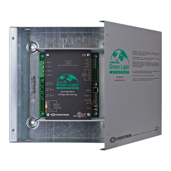
Page 9: Physical Description
Crestron Green Light Power Meter Control Unit Physical Description This section provides information on the connections, controls and indicators available on the GLS-EM-MCU. GLS-EM-MCU Physical View ® Operations Guide – DOC. 7294B Crestron Green Light Power Meter Control Unit: GLS-EM-MCU • 5... - Page 10 3/16 in 7 1/2 in (5 mm) (191 mm) 1 5/16 in Both Ends (34 mm) (12x) Knockouts for 1/2 in (13 mm) Conduit ® 6 • Crestron Green Light Power Meter Control Unit: GLS-EM-MCU Operations Guide – DOC. 7294B...
- Page 11 7 1/8 in (181 mm) 10 1/8 in (257 mm) 1 1/2 in (38 mm) 1 9/16 in 7 in (40 mm) (178 mm) ® Operations Guide – DOC. 7294B Crestron Green Light Power Meter Control Unit: GLS-EM-MCU • 7...
- Page 12 BRANCH CIRCUIT (1) 8-pin detachable terminal block to be MONITORS attached to a current transformer interface (GLS-EM-CTI) (Continued on following page) ® 8 • Crestron Green Light Power Meter Control Unit: GLS-EM-MCU Operations Guide – DOC. 7294B...
- Page 13 (1) 8-wire RJ-45 jack (8P8C modular female); 10BASE-T/100BASE-TX Ethernet port BRANCH CIRCUIT MONITORS CT1 – CT3, Interface connectors for INPUTS 1-4 ports are provided with the unit. ® Operations Guide – DOC. 7294B Crestron Green Light Power Meter Control Unit: GLS-EM-MCU • 9...
-
Page 14: Setup
The IP ID is set within the GLS-EM-MCU’s IP table using Crestron Toolbox™. For information on setting an IP table, refer to the Crestron Toolbox help file. The IP IDs of multiple GLS-EM-MCU devices in the same system must be unique. -
Page 15: Programming Software
Have a question or comment about Crestron software? Answers to frequently asked questions (FAQs) can be viewed in the Online Help section of the Crestron Web site. To post a question or view questions submitted to Crestron’s True Blue Support, log in at www.crestron.com/onlinehelp. First-time users must establish a user account to fully benefit from all available features. - Page 16 Crestron Green Light Power Meter Control Unit Crestron GLS-EM-MCU If additional GLS-EM-MCU devices are to be added, repeat step 1 for each device. Each GLS-EM-MCU is assigned a different IP ID number as it is added. If necessary, double click a device to open the “Device Settings” window and change the IP ID, as shown in the following illustration.
-
Page 17: Uploading And Upgrading
GLS-EM-MCU Crestron Toolbox The USB port on the GLS-EM-MCU connects to the USB port on the PC via the included Type A to Type B USB cable: Use the Address Book in Crestron Toolbox to create an entry using the expected communication protocol (USB). -
Page 18: Programs And Firmware
SIMPL Windows or Crestron Toolbox. Firmware Check the Crestron Web site to find the latest firmware. (New users may be required to register to obtain access to certain areas of the site, including the FTP site.) Upgrade GLS-EM-MCU firmware via Crestron Toolbox. -
Page 19: Configuration
The current transformer calibration code is a 21 character string that is stored within the GLS-EM-MCU. The code is placed on the label of the GLS-EM-CT and must be entered into the current transformer calibration field of the GLS Energy Meter Configuration Tool. -
Page 20: Problem Solving
Crestron worldwide offices on the Crestron Web site (www.crestron.com/offices) for assistance within a particular geographic region. To post a question about Crestron products, log onto the Online Help section of the Crestron Web site (www.crestron.com/onlinehelp). First-time users must establish a user account to fully benefit from all available features. -
Page 21: Future Updates
Crestron Green Light Power Meter Control Unit Future Updates As Crestron improves functions, adds new features and extends the capabilities of the GLS-EM-MCU, additional information may be made available as manual updates. These updates are solely electronic and serve as intermediary supplements prior to the release of a complete technical documentation revision. -
Page 22: Return And Warranty Policies
(property or economic damages inclusive) arising from the sale or use of this equipment. Crestron is not liable for any claim made by a third party or made by the purchaser for a third party. - Page 23 ® Crestron GLS-EM-MCU Crestron Green Light Power Meter Control Unit This page is intentionally left blank. ® Operations Guide – DOC. 7294B Crestron Green Light Power Meter Control Unit: GLS-EM-MCU • 19...
- Page 24 Crestron Electronics, Inc. Operations Guide – DOC. 7294B (2032458) 15 Volvo Drive Rockleigh, NJ 07647 Tel: 888.CRESTRON 09.12 Fax: 201.767.7576 Specifications subject to www.crestron.com change without notice.
Need help?
Do you have a question about the GLS-EM-MCU and is the answer not in the manual?
Questions and answers