Table of Contents
Advertisement
Quick Links
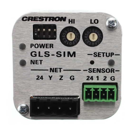
GLS-SIM
Sensor Integration Module
Installation and Operation Guide
Description
The GLS-SIM is a compact interface device designed to allow Crestron Green Light
sensors to be connected directly to a Cresnet
®
control network. Cresnet is the
communications backbone for Crestron
sensors, dimmers, keypads, touchpanels,
®
shade controllers, thermostats, and many other devices. This exible 4-wire bus provides
data communications and 24 Vdc power for all of the devices on the Cresnet network.
The GLS-SIM installs easily at the sensor location, mounting inside the electrical box or
exposed above the ceiling. Wiring connections to the network and sensor are facilitated
using miniature screw terminals.
GLS-SIM Speci cations
SPECIFICATION
DETAILS
Power Requirements
Cresnet Power Usage
1 W (0.04 A @ 24 Vdc)
(Does not include power draw of attached devices.)
Environmental
Temperature
32° to 104 °F (0° to 40 °C)
Humidity
0% to 95% RH (noncondensing)
Dimensions
Height
2.00 in (51 mm)
Width
2.00 in (51 mm)
Depth
0.86 in (22 mm)
Weight
2 oz (57 g)
Additional Resources
Visit the product page on the Crestron website (www.crestron.com)
for additional information and the latest rmware updates. Use a QR
reader application on your mobile device to scan the QR image.
Identity Code
The Net ID of the GLS-SIM has been factory set to 92 (with a mechanical setting of 00).
NOTE: The ID CODE switches on the GLS-SIM are factory set to 00. This allows
changing the Net ID with Crestron Toolbox™ software (optional).
The Net ID of the GLS-SIM can be set using one of two methods:
• Manual Setting: Set the two ID CODE switches (from 03 to FE) to match a Net ID in
the SIMPL Windows program.
• Touch-settable ID: Set the two ID CODE switches to 00 and set the Net ID using
Crestron Toolbox. This is the factory setting. For more details, refer to the Crestron
Toolbox help le.
ID CODE Switches
When setting the Net ID, consider the following:
• The Net ID of each unit must match an ID code speci ed in the control system
program.
• Each network device must have a unique Net ID.
Installation
®
NOTE: Observe the following points.
• Install and use this product in accordance with appropriate electrical codes and
regulations.
• If unsure about any part of these instructions, consult a quali ed electrician.
• Mount the sensor on a vibration-free surface.
• All sensors must be mounted at least 6 feet (1.8 m) away from air vents.
• Do not mount sensors closer than 10 feet (3 m) from each other.
• Do not touch the inner surface of the lens. Clean outer surface with a damp cloth
only.
NOTE: Before using the GLS-SIM, ensure the device is using the latest rmware.
Check for the latest rmware for the GLS-SIM at www.crestron.com/ rmware. Load
rmware onto the device using Crestron Toolbox software.
The GLS-SIM can be installed inside a standard 4-inch electrical box or mounted above
the ceiling using the included mounting bracket or the included dual-lock fastener. Use a
#1 Phillips screwdriver and the included screws to attach the included mounting bracket.
Attaching the Mounting Bracket to GLS-SIM (Optional)
0.20 in
(6 mm)
NOTE: Screws used for securing the GLS-SIM to a surface are not included.
Using a Dual-Lock Fastener on the GLS-SIM (Optional)
Mounting in an Octagon Back Box Installed Flush to a Drop Ceiling
Octagon back box
Drop ceiling
4 in x 1-1/2 in deep
GLS-SIM
Low-voltage
wires
#8-32 screws
(2 places)
Hardware Hookup
Make the necessary connections as called out in the illustration. Apply power after all
connections have been made.
CAUTION: Insuf cient power can lead to unpredictable results or damage to the
equipment. To help calculate how much power is needed for the system, use the
Crestron Power Calculator at www.crestron.com/calculators.
NOTE: Use Crestron Certi ed Wire.
NOTE: When making connections, strip the ends of the wires approximately 1/2 in
(13 mm). Use care to avoid nicking the conductors. Twist together the ends of the
wires that share a connection.
GLS-SIM Connections
2.88 in
(74 mm)
2.48 in
(63 mm)
NET:
SENSOR:
To control system
Sends power to
and other Cresnet
and receives input
devices
from sensor(s)
NOTE: The SENSOR port is a 4-pin 3.5 mm detachable terminal block. The sensor
input is comprised of 24 Vdc power output and two Versiports (referenced to GND),
5 V and 2k ohms pull-up resistor per pin.
NOTE: Depending on the available Cresnet power, the GLS-SIM can pass a maximum
of 1 A @ 24 Vdc to the devices or sensors that are connected to the SENSOR port.
Other Connections
The GLS-SIM can be con gured as a digital input, an analog input, or a digital output.
This setting is determined by the program running in the attached control processor.
Other settings are controlled by the DIP switches. Refer to the "Con guration" section for
diagrams that show how the GLS-SIM should be wired for each application.
CAUTION: Incorrect wiring may damage the GLS-SIM.
Con guration
Use the DIP switches to con gure the GLS-SIM to work with various device types, as
described in the following illustrations and associated tables.
DIP Switches on GLS-SIM
1 2 3 4
On
Off
INPUT
DIP
SETTING
CHANNEL
SWITCH
1
OFF: Enables pull-up resistor
ON: Disables pull-up resistor
1
2
OFF: Normal polarity
ON: Inverted polarity
3
OFF: Enables pull-up resistor
ON: Disables pull-up resistor
2
4
OFF: Normal polarity
ON: Inverted polarity
Sensor Digital Input
The GLS-SIM can be con gured for sensors that use relay contacts (normally open or
normally closed) or voltage level (active high or active low). The digital input is rated for
0–24 Vdc, the input impedance is 18.5k ohms, and the logic threshold is 1.25 Vdc.
Refer to the tables and wiring diagrams to con gure the GLS-SIM.
Switch Settings For Digital Input (Dry Contact Closure)
SENSOR
INPUT
DIP
24 1 2 G
SETTING
CHANNEL
SWITCH
1
OFF
1
2
OFF: Normally open
ON: Normally closed
Detecting a
contact
3
OFF
closure from
2
4
OFF: Normally open
a switch or
relay
ON: Normally closed
Switch Settings for Digital Input (Voltage Detection)
SENSOR
INPUT
DIP
SETTING
24 1 2 G
CHANNEL
SWITCH
1
ON
1
2
OFF: Active low
ON: Active high
Detecting
24 Vdc
3
ON
a low
max.
voltage
2
4
OFF: Active low
ON: Active high
Advertisement
Table of Contents

Related Manuals for Crestron GLS-SIM


Summary of Contents for Crestron GLS-SIM
- Page 1 The GLS-SIM can be con gured as a digital input, an analog input, or a digital output. 24 1 2 G SETTING The Net ID of the GLS-SIM has been factory set to 92 (with a mechanical setting of 00). Using a Dual-Lock Fastener on the GLS-SIM (Optional) CHANNEL SWITCH This setting is determined by the program running in the attached control processor.
- Page 2 Digital Output GLS-ODT-C connections are When using the GLS-SIM as a digital output, set the DIP switches as shown in the table correct. and wiring diagram. The digital output is a 250mA sink from a maximum of 24 Vdc, and...
Need help?
Do you have a question about the GLS-SIM and is the answer not in the manual?
Questions and answers