
Related Manuals for Kramer TP-125


Summary of Contents for Kramer TP-125
- Page 1 Kramer Electronics, Ltd. USER MANUAL Models: TP-125, UXGA / Audio / Data Line Transmitter TP-126, UXGA / Audio / Data Line Receiver...
-
Page 2: Table Of Contents
Figure 7: CAT 5 Connector Tables Table 1: TP-125 UXGA / Audio / Data Line Transmitter Features Table 2: Features of the TP-125 Internal Polarity Switches Table 3: TP-126 UXGA / Audio / Data Line Receiver (Top, Front, and Rear) Features... -
Page 3: Introduction
Converters and Scalers; GROUP 8: Cables and Connectors; GROUP 9: Room Connectivity; GROUP 10: Accessories and Rack Adapters; GROUP 11: Sierra Products 2 Download up-to-date Kramer user manuals from our Web site at http://www.kramerelectronics.com 3 The complete list of Kramer cables is on our Web site at http://www.kramerelectronics.com... -
Page 4: Quick Start
Getting Started Quick Start This quick start chart summarizes the basic setup and operation steps. KRAMER: SIMPLE CREATIVE TECHNOLOGY... -
Page 5: Overview
Level (gain) and EQ (peaking) controls (TP-126) System range up to 100m (300ft) This user manual describes the following Kramer TOOLS: TP-125 UXGA / Audio / Data Line Transmitter, see section 4.1 TP-126 UXGA / Audio / Data Line Receiver, see section 4.2 This section describes: Using shielded twisted pair (STP) / unshielded twisted pair (UTP), see section 3.1... -
Page 6: Recommendations For Achieving The Best Performance
It is recommended to use shielded twisted pair (STP) skew-free Kramer cable BC-SXTP for transmitting VGA signals, and shielded twisted pair (STP) non-skew-free Kramer BC-STP cable for digital signals. -
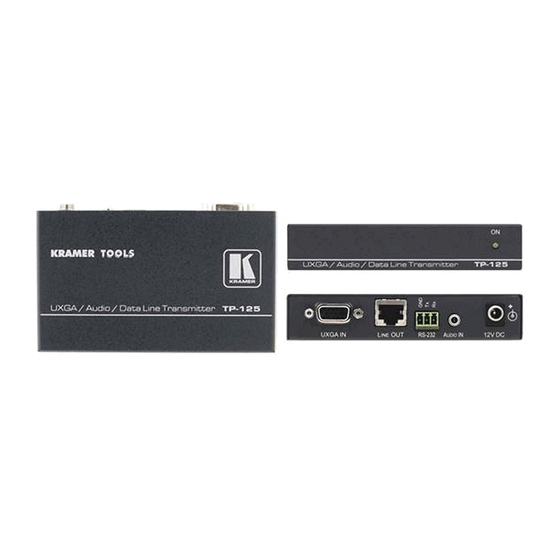
Page 7: Your Tp-125 Uxga / Audio / Data Line Transmitter
An unbalanced stereo analog audio signal RS-232 control commands The TP-125 codes the signals and transmits them over CAT 5 cable to a TP-126 receiver. The stereo analog audio signal is converted to the digital audio (S/PDIF) stream before transmitting, thus preserving the quality of the audio source signals. -
Page 8: 4.1.1 The Tp-125 Internal Polarity Switches
Figure 2 and Table 2 define the internal sync polarity switches inside the TP-125. Note, that you need to open the TP-125 unit to gain access to the Vs and Hs Polarity switches. After setting the switches, close the TP-125 unit. -
Page 9: Your Tp-126 Uxga / Audio / Data Line Receiver
Your TP-126 UXGA / Audio / Data Line Receiver The TP-126 is a high-performance receiver obtaining the computer graphics signal/audio/control data from the Kramer TP-125 via UTP cabling at its CAT 5 line input. The TP-126 outputs a computer graphics signal, an... -
Page 10: Your Tp-126 Uxga / Audio / Data Line Receiver (Underside)
Connects to the analog audio acceptor RS-232 Terminal Block Connector Connects to the controlled unit Connects to the LINE OUT RJ-45 connector on the TP-125 LINE IN RJ-45 Connector UXGA OUT 15-pin HD (F) Connector Connects to the UXGA acceptor... -
Page 11: Connecting The Tp-125/Tp-126 Transmitter/Receiver Pair
1 By default, both switches are set down (for a negative V SYNC and H SYNC polarity) 2 Not supplied. The full list of Kramer cables is on our Web site at http://www.kramerelectronics.com. Alternatively, you can connect an UXGA source to the UXGA IN 15-pin HD (F) connector, and a separate audio source to the AUDIO IN 3.5mm... -
Page 12: Figure 5: Connecting The Uxga / Audio / Data Line Transmitter / Receiver System
Connecting the TP-125/TP-126 Transmitter/Receiver Pair If necessary, set the H SYNC and V SYNC switches , on the underside Figure 5: Connecting the UXGA / Audio / Data Line Transmitter / Receiver System 1 By default, both switches are set down (for negative V SYNC and H SYNC polarity) -
Page 13: Transmitting Via Rs-232 (For Example, Using A Pc)
Connecting the TP-125/TP-126 Transmitter/Receiver Pair Transmitting via RS-232 (for example, using a PC) Prepare an RS-232 cable with a 9-pin D-sub connector at one end, and a 3 PIN terminal block connector at the other end, as defined in Table 5 and... -
Page 14: Technical Specifications
Technical Specifications Technical Specifications The TP-125, TP-126 technical specifications are shown in Table 7: Table 7: Technical Specifications of the TP-125 / TP-126 TP-125 TP-126 INPUTS: Video: 1 UXGA on an HD15 connector 1 RJ-45 LINE IN connector Audio: 1 audio ANALOG 3.5mm mini jack... - Page 16 For the latest information on our products and a list of Kramer distributors, visit our Web site: www.kramerelectronics.com where updates to this user manual may be found. We welcome your questions, comments and feedback. Safety Warning: Disconnect the unit from the power supply before opening/servicing.
Need help?
Do you have a question about the TP-125 and is the answer not in the manual?
Questions and answers