Table of Contents
Advertisement
Advertisement
Table of Contents

Subscribe to Our Youtube Channel
Related Manuals for Kramer TOOLS TP-122


Summary of Contents for Kramer TOOLS TP-122
-
Page 1: User Manual
Kramer Electronics, Ltd. USER MANUAL Models: TP-104, TP-104(HD), TP-105, TP-105(HD), TP-121, XGA / Audio Line Transmitter TP-122, XGA / Audio Line Receiver TP-123, XGA / Audio / Data Line Transmitter TP-124, XGA / Audio / Data Line Receiver XGA Line Transmitter / DA... -
Page 2: Table Of Contents
Figure 4: TP-121 XGA / Audio Line Transmitter Figure 5: TP-121 Internal Polarity Switches Figure 6: TP-122 XGA / Audio Line Receiver (Topside) Figure 7: TP-122 XGA / Audio Line Receiver (Underside) Figure 8: TP-123 XGA / Audio / Data Line Transmitter... - Page 3 Table 13: RS-232 PINOUT Connection Table 14: Technical Specifications of the TP-104 and the TP-104(HD) Table 15: Technical Specifications of the TP-105 and the TP-105(HD) Table 16: Technical Specifications of the TP-121 / TP-122 / TP-123 / TP-124 Contents KRAMER: SIMPLE CREATIVE TECHNOLOGY...
-
Page 4: Introduction
Congratulations on purchasing your Kramer TOOLS: TP-104, TP-104(HD) XGA Line Transmitter / DA, and/or TP-105, TP-105(HD), CAT5 Line Driver / DA, and/or TP-121 XGA / Audio Line Transmitter, and/or TP-122 XGA / Audio Line Receiver, and/or TP-123, XGA / Audio / Data Line Transmitter,... - Page 5 Getting Started KRAMER: SIMPLE CREATIVE TECHNOLOGY...
- Page 6 Getting Started...
-
Page 7: Overview
, and distributes it to 2 identical outputs, see section 5 TP-121 XGA / Audio Line Transmitter and the TP-122 XGA / Audio Line Receiver, see section 6 TP-123 XGA / Audio / Data Line Transmitter and the TP-124 XGA /... -
Page 8: Shielded Twisted Pair (Stp) / Unshielded Twisted Pair (Utp)
(often associated with low quality cables) Avoid interference from neighboring electrical appliances and position your Kramer TOOLS away from moisture, excessive sunlight and dust Caution Warning wall adapter that is provided with this unit Warning before installing or removing device or servicing unit. -
Page 9: Your Tp-104/Tp-104(Hd) Xga Line Transmitter / Da
) XGA Line Transmitter / DA +12V DC connector for powering the unit Connects to the LINE IN RJ-45 connector on the TP-122 XGA / Audio Line Receiver or the TP-120 XGA Line Receiver Connects to the LINE IN RJ-45 connector on the TP-122 XGA /... -
Page 10: Figure 2: Tp-104 (Underside Panel)
Your TP-104/TP-104(HD ) XGA Line Transmitter / DA Figure 2 and Table 2 define the TP-104 underside panel: Figure 2: TP-104 (Underside Panel) Table 2: TP-104 (Underside Panel) Features Feature VS Switch Slide the switch up (to NORMAL) to retain the polarity Slide the switch down HS Switch Slide the switch up (to NORMAL) to retain the polarity... -
Page 11: Your Tp-105/Tp-105(Hd) Cat5 Line Driver / Da
LINE IN RJ-45 connector on the TP-120 XGA Line Receiver Connects to the LINE OUT RJ-45 connector on the PT-110 XGA Line Transmitter Illuminates when receiving power Adjusts the video signal level Adjusts the video EQ. (equalization) compensation KRAMER: SIMPLE CREATIVE TECHNOLOGY Function... -
Page 12: Your Tp-121 / Tp-122
Your TP-121 / TP-122 This section defines the TP-121 XGA / Audio Line Transmitter (see section 6.1), and the TP-122 XGA / Audio Line Receiver (see section 6.2). 6.1 Your TP-121 XGA / Audio Line Transmitter The TP-121 is an XGA / audio stereo line transmitter that receives an XGA... -
Page 13: The Tp-121 Internal Polarity Switches
6.2.1 Your TP-122 XGA / Audio Line Receiver (Topside) The TP-122 is an XGA / audio line receiver that receives the coded CAT5 signal transmitted by a TP-121, decodes it and converts it to XGA, stereo analog and S/PDIF digital audio outputs. The TP-122, with a TP-121, allows an operation range of more than 300 ft. -
Page 14: Figure 6: Tp-122 Xga / Audio Line Receiver (Topside)
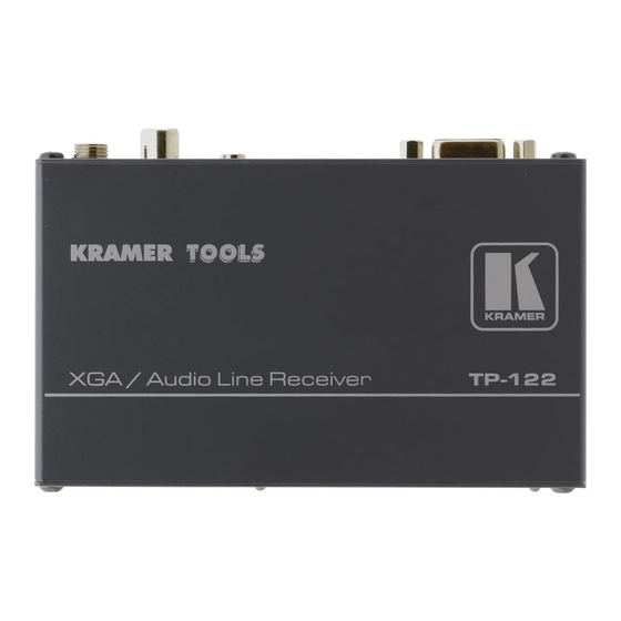
Includes EQ. and level controls Is 12VDC fed Figure 6 and Table 6 define the TP-122 XGA / Audio Line Receiver topside: Figure 6: TP-122 XGA / Audio Line Receiver (Topside) Table 6: TP-122 XGA / Audio Line Receiver (Topside) Features... -
Page 15: Your Tp-122 Xga / Audio Line Receiver (Underside)
Your TP-122 XGA / Audio Line Receiver (Underside) Figure 7 and Table 7 define the underside Receiver: Figure 7: TP-122 XGA / Audio Line Receiver (Underside Table 7: TP-122 XGA / Audio Line Receiver (Underside) Features Feature VS Switch Slide the switch up... -
Page 16: Your Tp-123 / Tp-124
Your TP-123 / TP-124 This section describes the TP-123 XGA / Audio / Data Line Transmitter (see section 7.1), and the TP-124 XGA / Audio / Data Line Receiver (see section 7.2). 7.1 Your TP-123 XGA / Audio / Data Line Transmitter... -
Page 17: The Tp-123 Internal Polarity Switches
/ Audio Line Receiver Connect to the XGA source Illuminates when receiving power NORM. Function , to set the V SYNC to negative polarity (NEG.); , to set the H SYNC to negative polarity (NEG.); KRAMER: SIMPLE CREATIVE TECHNOLOGY NEG. -
Page 18: Your Tp-124 Xga / Audio / Data Line Receiver
7.2 Your TP-124 XGA / Audio / Data Line Receiver The TP-124 is a high performance receiver obtaining the computer graphics signal/audio/control data from the Kramer TP-123 via UTP cabling at its CAT5 Line input. The TP-124 outputs a computer graphics signal, an unbalanced stereo analog audio signal, a converted digital audio (S/PDIF) signal and RS-232 control commands. -
Page 19: Your Tp-124 Xga / Audio / Data Line Receiver (Underside)
4 Use a screwdriver to carefully rotate the trimmer, adjusting the appropriate level 5 The underside is identical on the TP-122 and TP-124 6 By default, both switches are set down (for a negative V SYNC and H SYNC polarity) -
Page 20: Connecting The Xga / Audio Line Transmitter / Receiver
1 Not supplied. The complete list of Kramer cables is on our Web site at http://www.kramerelectronics.com 2 If you cannot connect the power to both the TP-121 and TP-122, you can just connect the power to the TP-122 3 Use a screwdriver to carefully rotate the trimmer, adjusting the appropriate level 4 By default, both switches are set down (for negative V SYNC and H SYNC polarity) the TP-121 and the TP-122. - Page 21 Connecting the XGA / Audio Line Transmitter / Receiver Figure 12: Connecting the XGA / Audio Line Transmitter / Receiver System KRAMER: SIMPLE CREATIVE TECHNOLOGY...
-
Page 22: Wiring The Cat5 Line In / Line Out Rj-45 Connectors
Connecting the XGA / Audio Line Transmitter / Receiver 8.1 Wiring the CAT5 LINE IN / LINE OUT RJ-45 Connectors Table 12 and Figure 13 define the UTP CAT5 PINOUT, using a straight pin to pin cable with RJ-45 connectors:... -
Page 23: Connecting The Xga / Audio / Data Line Transmitter / Receiver
If necessary, set the H SYNC and V SYNC switches 1 Not supplied. The full list of Kramer cables is on our Web site at http://www.kramerelectronics.com. Alternatively, you can connect an XGA source to the XGA IN HD15F connector, and a separate audio source to the AUDIO IN 3.5mm mini jack 2 As defined in Figure 15 and Table 13 (see section 8.1) - Page 24 Connecting the XGA / Audio / Data Line Transmitter / Receiver Figure 14: Connecting the XGA / Audio / Data Line Transmitter / Receiver System...
-
Page 25: Controlling Via Rs-232 (For Example, Using A Pc)
Connecting the XGA / Audio / Data Line Transmitter / Receiver 9.1 Controlling via RS-232 (for example, using a PC) Prepare an RS-232 cable with a DB9 connector at one end, and a 2 PIN terminal block connector at the other end, as defined in Figure 15 and Table 13:... -
Page 26: Configuring A 1:4 Xga To Tp Transmitter / Receiver / Da
XGA OUT HD15F connector of Unit IV to the XGA acceptor (for example, Display 4) 3. On each of the five Kramer TOOLS, connect the 12V DC power adapter to the power socket and connect the adapter to the mains electricity. - Page 27 Configuring a 1:4 XGA to TP Transmitter / Receiver / DA Figure 16: Configuring a 1:4 XGA to Twisted Pair Transmitter / Receiver / DA KRAMER: SIMPLE CREATIVE TECHNOLOGY...
-
Page 28: Configuring A Tp-105 Cat5 Line Driver / Da
XGA OUT HD15F connector on the second TP-120 unit to the XGA acceptor (for example, Display 2) 4. On each of the four Kramer units, connect the 12V DC power adapter to the power socket and connect the adapter to the mains electricity. - Page 29 Configuring a TP-105 CAT5 Line Driver / DA Figure 17: Configuring a TP-105 CAT5 Line Driver / DA KRAMER: SIMPLE CREATIVE TECHNOLOGY...
-
Page 30: Technical Specifications
Table 14 includes the technical specifications of the TP-104, Table 15 includes the technical specifications of the TP-105, and Table 16 includes the technical specifications of the TP-121, TP-122, TP-123, and TP-124: Table 14: Technical Specifications of the TP-104 INPUTS: OUTPUTS: MAX. -
Page 31: Table 16: Technical Specifications Of The Tp-121 / Tp-122 / Tp-123 / Tp-124
Table 16: Technical Specifications of the TP-121 / TP-122 / TP-123 / TP-124 TP-121 INPUTS: VIDEO: 1 VGA / UXGA on an HD15 connector AUDIO: 1 audio ANALOG 3.5mm mini jack OUTPUTS: 1 RJ-45 OUT connector MAX. OUTPUT LEVEL: CONTROLS: BANDWIDTH (-3dB) AUDIO: 20Hz –... - Page 32 EXCLUSION OF DAMAGES The liability of Kramer for any effective products is limited to the repair or replacement of the product at our option. Kramer shall not be liable for: 1. Damage to other property caused by defects in this product, damages based upon inconvenience, loss of use of the product, loss of time, commercial loss;...
- Page 33 For the latest information on our products and a list of Kramer distributors, visit our Web site: www.kramerelectronics.com, where updates to this user manual may be found. We welcome your questions, comments and feedback. Safety Warning: Disconnect the unit from the power supply before opening/servicing.
Need help?
Do you have a question about the TOOLS TP-122 and is the answer not in the manual?
Questions and answers