Table of Contents
Advertisement
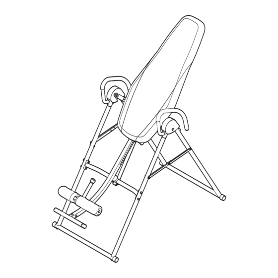
Model No. GGBE0867.0
Serial No.
Write the serial number in the
space above for future reference.
Serial Number Decal
QUESTIONS?
As a manufacturer, we are com-
mitted to providing complete cus-
tomer satisfaction. If you have
questions, or if parts are missing,
PLEASE DO NOT CONTACT
THE STORE; please contact
Customer Care.
IMPORTANT: You must note the
product model number and
serial number (see the drawing
above) before contacting us:
CALL TOLL-FREE:
1-877-776-4777
Mon.–Fri., 6 a.m.–6 p.m. MST
Sat. 8 a.m.–4 p.m. MST
ON THE WEB:
www.goldsgympowerflex.com
CAUTION
Read all precautions and instruc-
tions in this manual before using
this equipment. Save this manual
for future reference.
USER'S MANUAL
Advertisement
Table of Contents

Related Manuals for Gold's Gym GGBE0867.0


Summary of Contents for Gold's Gym GGBE0867.0
- Page 1 Model No. GGBE0867.0 Serial No. USER’S MANUAL Write the serial number in the space above for future reference. Serial Number Decal QUESTIONS? As a manufacturer, we are com- mitted to providing complete cus- tomer satisfaction. If you have questions, or if parts are missing, PLEASE DO NOT CONTACT THE STORE;...
-
Page 2: Table Of Contents
Apply the decal in the location shown. Note: The decals may not be shown at actual size. 194598 GOLD'S GYM is a registered trademark of Gold's Gym International, Inc. This product is manufactured and distributed under license from Gold's Gym International, Inc. -
Page 3: Important Precautions
IMPORTANT PRECAUTIONS WARNING: To reduce the risk of serious injury, read all important precautions and instructions in this manual and all warnings on your inversion system before using your inversion system. ICON assumes no responsibility for personal injury or property damage sustained by or through the use of the inversion system. -
Page 4: Before You Begin
BEFORE YOU BEGIN Thank you for selecting the versatile GOLD’S GYM model number and serial number before contacting us. ® INVERSION SYSTEM. The inversion system will The model number and the location of the serial num- increase your intervertebral dimension, decrease pres- ber decal are shown on the front cover of this manual. -
Page 5: Part Identification Chart
PART IDENTIFICATION CHART See the drawings below to identify small parts used in assembly. The number in parentheses by each drawing is the key number of the part, from the PART LIST near the end of this manual. Note: Some small parts may have been preattached. -
Page 6: Assembly
ASSEMBLY • For help identifying small parts, see the PART Make Assembly Easier IDENTIFICATION CHART on page 5. This manual is designed to ensure that the • As you assemble the inversion system, make sure inversion system can be assembled successfully that all parts are oriented as shown in the draw- by almost anyone. - Page 7 2. Attach the Front Leg Frame (5) to the Front Legs (1, 2) with four M8 x 45mm Button Bolts (43), four M8 Curved Washers (53), and four M8 Nylon Locknuts (54). Do not tighten the Nylon Locknuts yet. 3. Attach the two Bases (4) to the Front and Rear Legs (1, 2, 3) as shown with four M8 x 45mm Button Bolts (43).
- Page 8 5. Attach the Foot Frame (8) to the Adjustment Frame (7) with three M8 x 15mm Buttons Screws (47). 6. Slide the two Large Foam Pads (32) onto the Ankle Lock (9). Next, pull the Long Adjustment Knob (20), insert the Ankle Lock (9) into the Adjustment Frame (7), and then release the Long Hole Adjustment Knob.
- Page 9 8. Orient the two Pivot Bars (14) so that the Pulleys (22) face away from the Center Frame (13). Then, insert the Pivot Bars into the brack- ets on the ends of the Center Frame, and engage the pins on the brackets in the center adjustment holes in the Pivot Bars.
- Page 10 10. Attach the Backrest (23) to the Backrest Frame (6) with four M6 x 18mm Button Screws (50) and four M6 Flat Washers (51). 11. Attach the Right and Left Handles (15, 16) to the Legs (1, 2, 3) with four M8 Nylon Locknuts (54).
- Page 11 12. Slide the Left Cover (31) onto the left Saddle Plate (18). Attach the Left Cover with a Small Knob (42). Attach the Right Cover (30) in the same way. 13. Make sure that the Strap (28) is attached to the hook on the bottom of the Backrest Frame (6) with the Clip (27).
-
Page 12: Adjustment
ADJUSTMENT This section explains how to adjust the inversion system. See DEVELOPING A PROGRAM on page 16 for important information about how to get the most benefit from your exercise program. Make sure all parts are properly tightened each time the inversion system is used. Replace any worn parts immedi- ately. -
Page 13: Adjusting Adjustment Frame/Ankle Lock
ADJUSTING THE ADJUSTMENT FRAME The length of the Adjustment Frame (7) can be adjusted to correspond to your height. First, remove the Pin (24) from the Backrest Frame (6) and the Adjustment Frame. Pull the Short Adjustment Knob (19) as far as possible. Slide the Adjustment Frame into or out of the Backrest Frame so that the first or second measurement greater than your height is cov- Height... -
Page 14: Locking/Storing Inversion System
LOCKING THE INVERSION SYSTEM When the inversion system is not in use, it should be locked to prevent unsupervised use. Wrap the Lock Cable (62) around the Front Leg Frame (5) and the Adjustment Frame (7) as shown. Then, connect the ends of the Lock Cable with an M8 x 20mm Button Bolt (64) and an M8 Nylon Locknut (54). -
Page 15: Rotating On The Inversion System
ROTATING ON THE INVERSION SYSTEM This section explains how to rotate back on the inversion system, and then return to the starting position. Before using the inversion system, see the ADJUSTMENT section starting on page 13 to correctly set up the inversion system. -
Page 16: Developing A Program
DEVELOPING A PROGRAM This section contains information and suggestions about using the inversion system. Make sure that all parts are properly tightened each time you use the inversion system. Replace any worn parts immediately. See the ADJUSTMENT section starting on page 12 to identify parts referred to in this section. BENEFITING FROM USING THE INVERSION INTERMEDIATE PROGRAM SYSTEM... - Page 17 NOTES...
-
Page 18: Part List
PART LIST—Model No. GGBE0867.0 R0807A Key No. Qty. Description Key No. Qty. Description Right Front Leg 32mm Round Outer Cap Left Front Leg Bumper Rear Leg 25mm Round Inner Cap Base 30mm x 70mm Inner Cap Front Leg Frame Foam Grip... -
Page 19: Exploded Drawing
EXPLODED DRAWING—Model No. GGBE0867.0 R0807A 39 40 5 54... -
Page 20: Ordering Replacement Parts
ORDERING REPLACEMENT PARTS To order replacement parts, please see the front cover of this manual. To help us assist you, be prepared to pro- vide the following information when contacting us: • the model number and serial number of the product (see the front cover of this manual) •...
Need help?
Do you have a question about the GGBE0867.0 and is the answer not in the manual?
Questions and answers