
Related Manuals for Avalue Technology BBM-BSW A2


Summary of Contents for Avalue Technology BBM-BSW A2
- Page 1 BBM-BSW A2 Intel® Celeron® Processor N3160 Thin Mini ITX Motherboard User’s Manual Ed – 12 February 2020 Part No. E2047BBMB02R...
- Page 2 Disclaimer Avalue Technology Inc. reserves the right to make changes, without notice, to any product, including circuits and/or software described or contained in this manual in order to improve design and/or performance. Avalue Technology assumes no responsibility or liability for the...
- Page 3 Applications that are described in this manual are for illustration purposes only. Avalue Technology Inc. makes no representation or warranty that such application will be suitable for the specified use without further testing or modification.
- Page 4 A product returned without proof of the purchase date is not eligible for warranty service. Write the RMA number visibly on the outside of the package and ship it prepaid to your dealer. 4 BBM-BSW A2 User’s Manual...
-
Page 5: Table Of Contents
2.3.20 EC program connector (JEC_ROM1) .................... 31 2.3.21 SPI Program connector (JSPI1) ....................31 2.3.22 eDP connector (JEDP1) ........................ 32 2.3.23 Half size mPCIE slot support SATA SSD (MSATA1) ..............33 2.3.24 M.2 B Key connector (M.2_1) ......................34 BBM-BSW A2 User’s Manual... - Page 6 3.6.3.1.3 Dual Display Control (Only support CSM Legacy mode) ............58 3.6.3.2 South Bridge ........................58 3.6.3.2.1 Security Configuration ......................59 3.6.3.2.2 Azalia Configuration ......................60 3.6.3.2.3 USB Configuration ......................... 60 3.6.4 Security ............................61 3.6.4.1 Secure Boot menu ....................... 62 3.6.4.1.1 Key Management........................63 6 BBM-BSW A2 User’s Manual...
- Page 7 User’s Manual 3.6.5 Boot .............................. 63 3.6.6 Save and exit ..........................64 4. Mechanical Drawing ....................65 BBM-BSW A2 User’s Manual...
-
Page 8: Getting Started
1.2 Packing List Before you begin installing your single board, please make sure that the following materials have been shipped: 1 x BBM-BSW A2 motherboard 1 x Heat sink 8 BBM-BSW A2 User’s Manual... -
Page 9: Document Amendment History
User’s Manual 1.3 Document Amendment History Revision Date Comment A1 1 July 2017 Avalue Initial Release A2 1 August 2018 Avalue Update Setting Jumpers & Connectors A2 2 February 2020 Avalue Update BIOS setup BBM-BSW A2 User’s Manual... -
Page 10: Manual Objectives
We strongly recommend that you study this manual carefully before attempting to set up BBM-BSW A2 or change the standard configurations. Whilst all the necessary information is available in this manual we would recommend that unless you are confident, you contact your supplier for guidance. -
Page 11: System Specifications
Mini Display Port + LVDS or eDP(optional) LVDS Chip Realtek Chrontel CH-7511 eDP to LVDS transmitter Audio Audio Codec Realtek ALC892 Mic-in, Line-out with AMP Interface PCBEEP Ethernet LAN Chip 1 x Intel I211AT Gigabit Ethernet BBM-BSW A2 User’s Manual 11... - Page 12 1 x 2 x 10 pin, pitch 2.54mm box header for GPIO: 16bits 1 x 2 x 8 pin, pitch 2.54mm box header w/o pin2 for Audio 1 x 2 x 5 pin, pitch 2.0mm connector for LPC 12 BBM-BSW A2 User’s Manual...
- Page 13 The PS_ON line should not change its state if we do a software reboot. (Should keep the active low state). The PS_ON line should go to high impedance if we do a software shutdown. Necessary circuit simulates the PS_ON function, selectable with a jumper. Operating Temp. 5 ~ 70°C BBM-BSW A2 User’s Manual 13...
- Page 14 BBM-BSW A2 User’s Manual Storage Temp. -20 ~ 60°C Storing: 10% ~ 90% Real Humidity Operation: 10% ~ 70% Size (L x W) 170mm x 170mm Weight 0.38 kg Note: Specifications are subject to change without notice. 14 BBM-BSW A2 User’s Manual...
-
Page 15: Architecture Overview-Block Diagram
User’s Manual 1.6 Architecture Overview—Block Diagram The following block diagram shows the architecture and main components of BBM-BSW A2. BBM-BSW A2 User’s Manual 15... -
Page 16: Information
BBM-BSW A2 User’s Manual 1.7 Information 16 BBM-BSW A2 User’s Manual... -
Page 17: Hardware Configuration
User’s Manual 2. Hardware Configuration BBM-BSW A2 User’s Manual 17... -
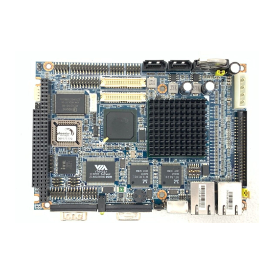
Page 18: Product Overview
BBM-BSW A2 User’s Manual 2.1 Product Overview 18 BBM-BSW A2 User’s Manual... -
Page 19: Jumper And Connector List
LVDS Backlight ADJ 5V/3.3V level 3 x 1 header, pitch 2.00mm JBKLADJ1 select LVDS Backlight EN 5V/3.3V level JBKLEN1 3 x 1 header, pitch 2.00mm select Connectors Label Function Note LAN1 RJ-45 Ethernet BBM-BSW A2 User’s Manual 19... - Page 20 3 x 1 header, pitch 2.00mm JEC_ROM1 2 x 4 header without pin 8, pitch JSPI1 SPI Program connector 2.00mm JBKL1 LVDS Backlight connector 4 x 1 wafer, pitch 2.00mm JLPT1 Printer Port 13 x 2 Box header, pitch 2.54mm 20 BBM-BSW A2 User’s Manual...
-
Page 21: Setting Jumpers & Connectors
User’s Manual 2.3 Setting Jumpers & Connectors 2.3.1 Clear CMOS (JPCMOS1) Protect* Clear CMOS * Default 2.3.2 PS_ON function selector (JPSON_SEL1) Support PS_ON function* Don’t support PS_ON function * Default BBM-BSW A2 User’s Manual 21... -
Page 22: Com2 Rs232 Or Rs422 Selector (Jp232/422_1)
BBM-BSW A2 User’s Manual 2.3.3 COM2 RS232 or RS422 selector (JP232/422_1) RS232* RS422 * Default 2.3.4 NDS/Omni Boot sequence and LVDs panel selector (JPBOOT_SEQ1) NDS boot sequence and TM150TDS50* Omni boot sequence and G121XN01V0 * Default 22 BBM-BSW A2 User’s Manual... -
Page 23: Lvds Backlight Adj 5V/3.3V Level Select (Jbkladj1)
User’s Manual 2.3.5 LVDS Backlight ADJ 5V/3.3V level select (JBKLADJ1) LVDS_BKLADJ_OUT 3.3V level* LVDS_BKLADJ_OUT 5V level 2.3.6 LVDS Backlight EN 5V/3.3V level select (JBKLEN1) LVDS_BKLTEN_OUT 3.3V level* LVDS_BKLTEN_OUT 5V level BBM-BSW A2 User’s Manual 23... -
Page 24: Usb2.0 Connector 3/4/5/6/7/8 (Usb3/4/5/6/7/8)
+5VSB USB_N USB_P Note: USB5/6/7/8 don’t support wake up from S3, S4 and S5. 2.3.8 Serial port 1/3/4 connector (JCOM1/3/4) JCOM3 Signal PIN PIN Signal NDCD# NDSR# NRXD NRTS# NTXD NCTS# JCOM1 JCOM4 NDTR# NRI# 24 BBM-BSW A2 User’s Manual... -
Page 25: Serial Port 2 Connector (Jcom2)
User’s Manual 2.3.9 Serial port 2 connector (JCOM2) Signal PIN PIN Signal NDCD# NDSR# NRXD NRTS# NTXD NCTS# NDTR# NRI# 2.3.10 COM2 RS422 connector (JRS422_1) Signal PIN PIN Signal 422TX 422RX- 422TX+ 422RX+ BBM-BSW A2 User’s Manual 25... -
Page 26: Lvds Backlight Connector (Jbkl1)
BBM-BSW A2 User’s Manual 2.3.11 LVDS Backlight connector (JBKL1) Signal +12V LVDS_BKLTEN_OUT LVDS_BKLADJ_OUT 2.3.12 General purpose I/O connector (JDIO1) Signal PIN PIN Signal SMB_CLK SMB_DATA 26 BBM-BSW A2 User’s Manual... -
Page 27: Printer Port (Jlpt1)
PIN PIN Signal PT_STB- PT_AFD# PTD0 ERR# PTD1 PT_PAR_INIT# PTD2 PT_SLIN# PTD3 PTD4 PTD5 PTD6 PTD7 ACK# BUSY SLCT 2.3.14 Audio connector (JAUDIO1) Signal PIN PIN Signal PCBEEP 15 MIC1-MONO-IN OUT_L_W_AMP_C 14 OUT_R_W_C OUT_R OUT_L OUT_l_W_C BBM-BSW A2 User’s Manual 27... -
Page 28: Lvds Connector (Jlvds1)
PIN PIN Signal +3.3V +3.3V +3.3V +3.3V LVDS_DATAP0 LVDS_DATAP LVDS_DATAN0 11 LVDS_DATAN1 LVDS_DATAP2 15 LVDS_DATAP3 LVDS_DATAN2 17 LVDS_DATAN3 LVDS_DATAP4 21 LVDS_DATAP5 LVDS_DATAN4 23 LVDS_DATAN5 LVDS_DATAP6 27 LVDS_DATAP7 LVDS_DATAN6 29 LVDS_DATAN7 LVDS_CLK1P LVDS_CLK2P LVDS_CLK1N LVDS_CLK2N +12V +12V 28 BBM-BSW A2 User’s Manual... -
Page 29: Power Connector (Pwr1)
User’s Manual 2.3.16 Power connector (PWR1) Signal PIN PIN Signal +V11P4_30V_IN +V11P4_30V_IN 2.3.17 Power control signal connector (ATXCTRL1) Signal Signal ATX_RESET# ATX_PS_ON# BBM-BSW A2 User’s Manual 29... -
Page 30: Front Panel Connector (Jfp1)
BBM-BSW A2 User’s Manual 2.3.18 Front Panel connector (JFP1) Signal PIN PIN Signal HDD_LED+ PWR_LED+ HDD_LED- PWR_LED- FP_RST# PWR_BTN# 2.3.19 LPC connector (JLPC1) Signal PIN PIN Signal LPC_AD0 +3.3V LPC_AD1 PLT_RST# LPC_AD2 LPC_FRAME# LPC_AD3 LPC_CLK LPC_SERIRQ 30 BBM-BSW A2 User’s Manual... -
Page 31: Ec Program Connector (Jec_Rom1)
User’s Manual 2.3.20 EC program connector (JEC_ROM1) Signal EC_SMBCLK EC_SMBDATA 2.3.21 SPI Program connector (JSPI1) Signal PIN PIN Signal +V1.8_SPI SPI_CS0# SPI_CLK SPI_MISO SPI_MOSI SPI_HOLD# BBM-BSW A2 User’s Manual 31... -
Page 32: Edp Connector (Jedp1)
BBM-BSW A2 User’s Manual 2.3.22 eDP connector (JEDP1) Signal 12 EDP_Panel_CM_TXN0 13 EDP_Panel_CM_TXP0 EDP_Panel_AUXP EDP_Panel_AUXN +3.3V +3.3V +3.3V +3.3V EDP_Panel_HPD Signal EDP_Panel_BKLTEN EDP_Panel_BKLTCTL EDP_Panel_TXN3 EDP_Panel_TXP3 +12V EDP_Panel_CM_TXN2 +12V EDP_Panel_CM_TXP2 +12V +12V EDP_Panel_CM_TXN1 10 EDP_Panel_CM_TXP1 32 BBM-BSW A2 User’s Manual... -
Page 33: Half Size Mpcie Slot Support Sata Ssd (Msata1)
User’s Manual 2.3.23 Half size mPCIE slot support SATA SSD (MSATA1) Signal PIN PIN Signal +3.3VSB SATA_RXP0 +3.3VSB SATA_RXN0 SATA_TXP0 SATA_TXN0 +3.3VSB +3.3VSB +3.3V +3.3VSB BBM-BSW A2 User’s Manual 33... -
Page 34: B Key Connector (M.2_1)
M.2_SATA_RXP _PCIE_RXN0 M.2_SATA_RXN Signal PIN PIN Signal _PCIE_RXP0 CONFIG_3 +3.3VSB +3.3VSB M.2_SATA_TXN FULL_CARD_PWR_OFF# _PCIE_TXN0 M.2_USB_DP4 M.2_W_DISABLE1# M.2_SATA_TXP M.2_RST# M.2_USB_DN4 DAS_DSS# _PCIE_TXP0 M.2_CLKREQ# PCIE_CLKN0 M.2_WAKE1# CONFIG_0 PCIE_CLKP0 M.2_1.8V_WAKE# 23 M.2_1.8V_W_DISABLE2# SIM_DETECT M.2_1.8V_WWAN SOC_PMU_SUSCLK _RESET# CONFIG_1 CONFIG_2 34 BBM-BSW A2 User’s Manual... -
Page 35: Mini Display Port (Mdp1)
User’s Manual 2.3.25 Mini Display Port (MDP1) Signal PIN PIN Signal DP_HPD DP_C_TXP0 CFG1 DP_C_TXN0 CFG2 DP_C_TXP1 DP_C_TXP3 DP_C_TXN1 DP_C_TXN3 DP_C_TXP2 16 DDI1_AUXP_R DP_C_TXN2 18 DDI1_AUXN_R +3.3V BBM-BSW A2 User’s Manual 35... -
Page 36: Bios Setup
BBM-BSW A2 User’s Manual 3.BIOS Setup 36 BBM-BSW A2 User’s Manual... -
Page 37: Introduction
If you do not press the keys at the correct time and the system does not boot, an error message will be displayed and you will again be asked to. Press F1 to Continue, DEL to enter SETUP BBM-BSW A2 User’s Manual 37... -
Page 38: Using Setup
Note: Some of the navigation keys differ from one screen to another. To Display a Sub Menu Use the arrow keys to move the cursor to the sub menu you want. Then press <Enter>. A “” pointer marks all sub menus. 38 BBM-BSW A2 User’s Manual... -
Page 39: Getting Help
BIOS Vendor and your systems manufacturer to provide the absolute maximum performance and reliability. Even a seemingly small change to the chipset setup has the potential for causing you to use the override. BBM-BSW A2 User’s Manual 39... -
Page 40: Bios Setup
<Enter> to accept and enter the sub-menu. 3.6.1 Main Menu This section allows you to record some basic hardware configurations in your computer and set the system clock. 40 BBM-BSW A2 User’s Manual... -
Page 41: System Language
Visit the Avalue website (www.avalue.com.tw) to download the latest product and BIOS information. 3.6.2 Advanced Menu This section allows you to configure your CPU and other system devices for basic operation through the following sub-menus. BBM-BSW A2 User’s Manual 41... -
Page 42: Acpi Settings
ACPI Sleep State system will enter when the SUSPEDN S3 (Suspend to RAM)[Default] button is pressed. Disabled[Default], 30 sec 40 sec 50 sec Watch Dog Select WatchDog. 1 min 2 min 10 min 30 min 42 BBM-BSW A2 User’s Manual... -
Page 43: It8528 Super Io Configuration
Set Parameters of Serial Port 1 (COMA). Serial Port 2 Configuration Set Parameters of Serial Port 2 (COMB). Serial Port 3 Configuration Set Parameters of Serial Port 3 (COMC). Serial Port 4 Configuration Set Parameters of Serial Port 4 (COMD). BBM-BSW A2 User’s Manual 43... -
Page 44: Serial Port 1 Configuration
3.6.2.2.1 Serial Port 1 Configuration Item Option Description Enabled[Default], Serial Port Enable or Disable Serial Port (COM). Disabled Auto[Default] IO=3F8h; IRQ=4; IO=3F8h; IRQ=3,4,5,6,7,9,10,11,12; Select an optimal setting for Super IO Change Settings IO=2F8h; IRQ=3,4,5,6,7,9,10,11,12; Device. IO=3E8h; IRQ=3,4,5,6,7,9,10,11,12; IO=2E8h; IRQ=3,4,5,6,7,9,10,11,12; 44 BBM-BSW A2 User’s Manual... -
Page 45: Serial Port 2 Configuration
3.6.2.2.2 Serial Port 2 Configuration Item Option Description Enabled[Default], Serial Port Enable or Disable Serial Port (COM). Disabled Auto[Default] IO=2F8h; IRQ=3; IO=3F8h; IRQ=3,4,5,6,7,9,10,11,12; Select an optimal setting for super IO Change Settings IO=2F8h; IRQ=3,4,5,6,7,9,10,11,12; Device. IO=3E8h; IRQ=3,4,5,6,7,9,10,11,12; IO=2E8h; IRQ=3,4,5,6,7,9,10,11,12; BBM-BSW A2 User’s Manual 45... -
Page 46: Serial Port 3 Configuration
3.6.2.2.3 Serial Port 3 Configuration Item Option Description Enabled[Default], Serial Port Enable or Disable Serial Port (COM). Disabled Auto[Default] IO=3E8h; IRQ=10; IO=3E8h; IRQ=3,4,5,6,7,10,11,12; Select an optimal setting for super IO Change Settings IO=2E8h; IRQ=3,4,5,6,7,10,11,12; Device. IO=200h; IRQ=3,4,5,6,7,10,11,12; IO=208h; IRQ=3,4,5,6,7,10,11,12; 46 BBM-BSW A2 User’s Manual... -
Page 47: Serial Port 4 Configuration
3.6.2.2.4 Serial Port 4 Configuration Item Option Description Enabled[Default], Serial Port Enable or Disable Serial Port (COM). Disabled Auto[Default] IO=2E8h; IRQ=11; IO=3E8h; IRQ=3,4,5,6,7,10,11,12; Select an optimal setting for super IO Change Settings IO=2E8h; IRQ=3,4,5,6,7,10,11,12; Device. IO=200h; IRQ=3,4,5,6,7,10,11,12; IO=208h; IRQ=3,4,5,6,7,10,11,12; BBM-BSW A2 User’s Manual 47... -
Page 48: Ec 8525 H/W Monitor
BBM-BSW A2 User’s Manual 3.6.2.3 EC 8525 H/W Monitor 3.6.2.4 NCT6106D Super IO Configuration 48 BBM-BSW A2 User’s Manual... -
Page 49: Parallel Port Configuration
IO=278h; IRQ=5,6,7,9,10,11,12; IO=3BCh; IRQ=5,6,7,9,10,11,12; STD Printer Mode[Default] SPP Mode EPP-1.9 and SPP Mode Device Mode EPP-1.7 and SPP Mode Change the Printer Port mode. ECP Mode ECP and EPP1.9 Mode ECP and EPP 1.7 Mode BBM-BSW A2 User’s Manual 49... -
Page 50: Cpu Configuration
Enable the power management features. Custom[Default] Disabled, EIST Enable/Disable Intel SpeedStep. Enabled[Default] Disabled, Turbo Mode Turbo Mode. Enabled[Default] HW_ALL[Default] P-STATE Coordination SW_ALL Change P-STATE Coordination type. SW_ANY Package C State limit C1[Default]/C3/C6/C7 Package C State limit. 50 BBM-BSW A2 User’s Manual... -
Page 51: Socket 0 Cpu Information
User’s Manual 3.6.2.5.1 Socket 0 CPU Information 3.6.2.6 SATA Configuration Item Options Description Disabled, SATA Controller Enable/Disable SATA Device. Enabled[Default] SATA Mode Selection AHCI[Default] Determines how SATA controller operate. BBM-BSW A2 User’s Manual 51... -
Page 52: Miscellaneous Configuration
Select SATA Interface Speed, CHV A1 always SATA Interface Speed Gen2 with Gen 1 Speed. Gen3[Default] Disabled, Port0/1 Enable/Disable SATA Port. Enabled[Default] 3.6.2.7 Miscellaneous Configuration Item Options Description Win8/Win10 BOM Config Legacy System (WIN 7) BOM Config. Yocto Linux[Default] 52 BBM-BSW A2 User’s Manual... -
Page 53: Csm Configuration
Network UEFI PXE OpROM. Legacy Do not launch Controls the execution of UEFI and Legacy Storage UEFI[Default] Storage OpROM. Legacy Do not launch Controls the execution of UEFI and Legacy Video UEFI Video OpROM. Legacy[Default] BBM-BSW A2 User’s Manual 53... -
Page 54: Usb Configuration
Root port it is 100ms, for a Hub port the delay is taken form Hub descriptor. Mass storage device emulation type. ‘AUTO’ Auto[Default] Mass Storage Devices Floppy enumerates devices according to their media 54 BBM-BSW A2 User’s Manual... -
Page 55: Chipset
User’s Manual format. Optical drives are emulated as ‘CDROM’, Forced FDD Hard Disk drives with no media will be emulated according CD-ROM to a drive type. 3.6.3 Chipset 3.6.3.1 North Bridge BBM-BSW A2 User’s Manual 55... -
Page 56: Intel Igd Configuration
(Fixed) Graphics Memory size used /384M/416M/448M/480M/512M by the Internal Graphics Device. 128MB Select DVMT 5.0 Total Graphic DVMT Total Gfx Mem 256MB[Default] Memory size used by the Internal Graphics Device. Enabled[Default], Enable/Disable Spread Spectrum Spread Spectrum clock Disabled clock. 56 BBM-BSW A2 User’s Manual... -
Page 57: Igd - Lcd Control
Option Description Enabled[Default] Active Internal LVDS(eDP->Ch7511- Active LVDS (Ch7511) to –LVDS). Disabled LVDS Back Light PWM Select LVDS back light PWM duty. 100%[Default] 200[Default] LVDS Back Light PWM Frequency Select LVDS back light PWM Frequency. BBM-BSW A2 User’s Manual 57... -
Page 58: Dual Display Control (Only Support Csm Legacy Mode)
POST. This has no effect if external graphics DP to HDMI Primary IGFX Boot Display present. Secondary boot display selection will LVDS appear based on your selection. VGA modes will be DP to VGA supported only on primary display. 3.6.3.2 South Bridge 58 BBM-BSW A2 User’s Manual... -
Page 59: Security Configuration
Description Enabled Wake On Lan Enable/Disable Wake On Lan. Disabled[Default] Enabled Wake On Ring Enable/Disable Wake On Ring. Disabled[Default] 3.6.3.2.1 Security Configuration Item Option Description Enabled BIOS Lock Enable/Disable the BIOS Lock Enable feature. Disabled[Default] BBM-BSW A2 User’s Manual 59... -
Page 60: Azalia Configuration
BBM-BSW A2 User’s Manual 3.6.3.2.2 Azalia Configuration Item Option Description Control Detection of the Azalia device. Disabled = Azalia Enabled[Default], Audio Controller will be unconditionally disabled. Enabled = Azalia will be Disabled unconditionally Enabled. 3.6.3.2.3 USB Configuration 60 BBM-BSW A2 User’s Manual... -
Page 61: Security
User’s Manual Item Option Description Enabled[Default], XHCI Mode Mode of operation of xHCI controller. Disabled 3.6.4 Security Administrator Password Set setup Administrator Password User Password Set User Password BBM-BSW A2 User’s Manual 61... -
Page 62: Secure Boot Menu
Secure Boot User mode with enrolled Platform Key(PK) 2.CSM Enabled function is disabled. Secure Boot mode selector. ‘Custom’ Mode Standard Secure Boot Mode enables users to change Image Execution policy Custom[Default] and manage Secure Boot Keys. 62 BBM-BSW A2 User’s Manual... -
Page 63: Key Management
User’s Manual 3.6.4.1.1 Key Management Item Option Description Enabled, Install Factory default Secure Boot Keys Provision Factory Default Keys Disabled[Default] when System is in Setup Mode. 3.6.5 Boot BBM-BSW A2 User’s Manual 63... - Page 64 BIOS setting. Launch EFI Shell from Attempts to Launch EFI Shell application (Shellx64.efi) from one of the filesystem device available filesystem devices. 64 BBM-BSW A2 User’s Manual...
- Page 65 User’s Manual 4. Mechanical Drawing BBM-BSW A2 User’s Manual 65...
- Page 66 BBM-BSW A2 User’s Manual Unit: mm 66 BBM-BSW A2 User’s Manual...
- Page 67 User’s Manual Unit: mm BBM-BSW A2 User’s Manual 67...
Need help?
Do you have a question about the BBM-BSW A2 and is the answer not in the manual?
Questions and answers